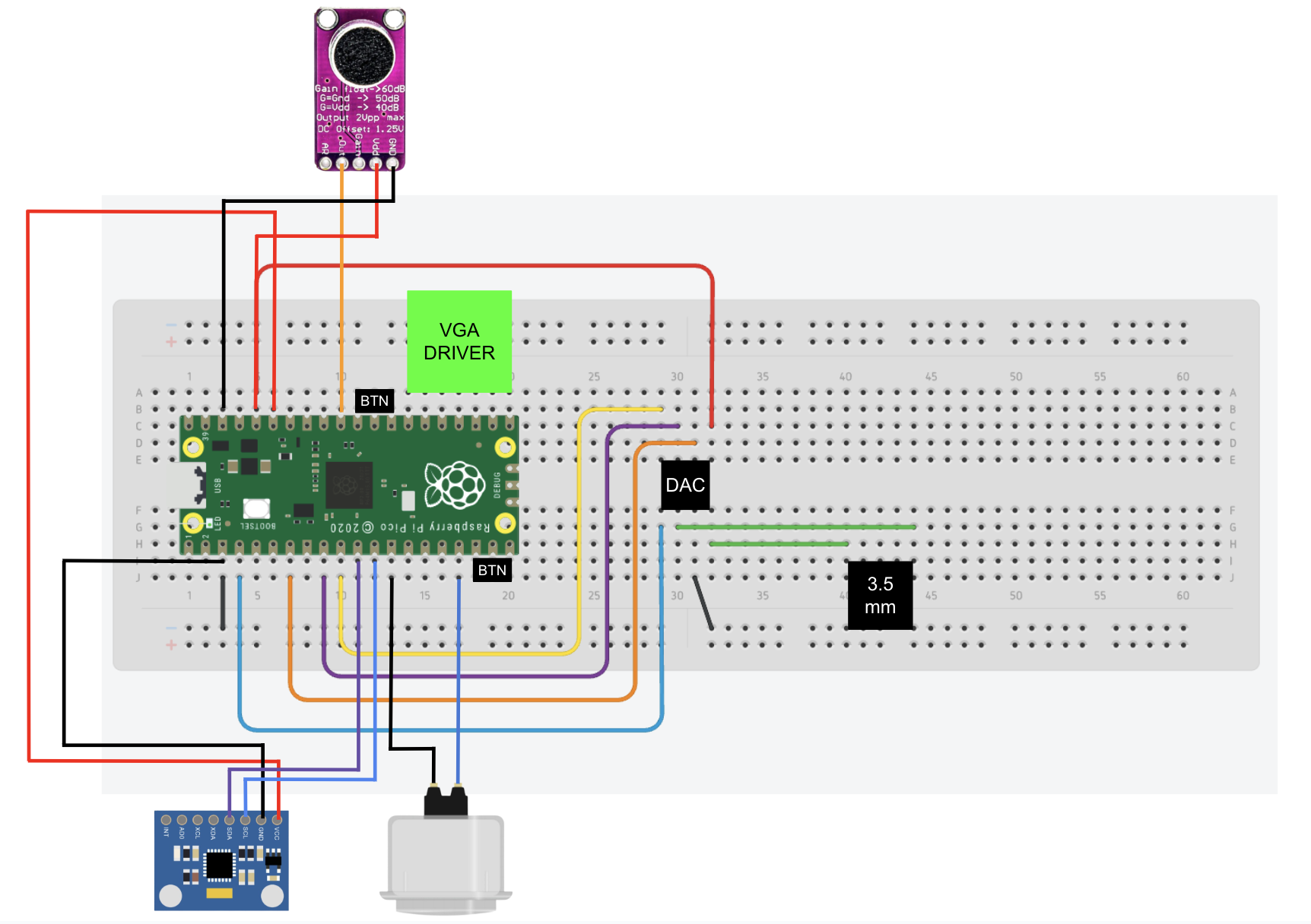
The system is built around a Raspberry Pi Pico (RP2040) mounted on a solderless breadboard and powered over USB. The RP2040 serves as the central controller for graphics, audio, and user input. All peripherals share a common ground, and 3.3 V power is distributed from the Pico to the attached sensors and breakout boards. The dual-core architecture of the RP2040 allows time-critical VGA graphics and game logic to run independently from asynchronous input handling. The button, microphone, and IMU were each mounted in a custom 3D-printed stand designed in Autodesk Fusion, providing stable positioning and making the different control modes easier to use during gameplay as shown in the images below.
Video output is generated as a standard 640×480 VGA signal using the RP2040’s PIO state machines and DMA to meet strict timing requirements. Horizontal sync, vertical sync, and RGB color signals are driven directly from GPIO pins through a resistor-ladder digital-to-analog converter. This VGA hardware design and pin-mapping approach are adapted from the Cornell ECE 4760 RP2040 VGA graphics libraries developed by Bruce Land and Hunter Adams, which provided the baseline timing configuration and signal generation strategy.
Audio output is handled by an external SPI digital-to-analog converter connected to the RP2040 via GPIO pins for data, clock, and chip select. The DAC output is routed to a 3.5 mm audio jack to support headphones or external speakers. Sound effects are streamed using DMA for low-latency playback, while background audio is synthesized in software. The DAC wiring and DMA-based audio pipeline follow the Cornell ECE 4760 RP2040 audio examples by Hunter Adams, with modifications for our specific pin assignments and game logic.
Voice-based control is implemented using an Adafruit MAX9814 microphone amplifier. The module is powered at 3.3 V, and its analog output is connected to one of the RP2040’s ADC pins. The MAX9814’s built-in automatic gain control allows the system to detect claps or short vocal bursts reliably without additional analog filtering, enabling microphone-based flapping as an alternative control mode.
Motion-based control is provided by an MPU6050 accelerometer and gyroscope connected to the RP2040 over the I²C interface. The IMU is sampled periodically to measure orientation and acceleration, and a tilt-based metric derived from the accelerometer data is used to trigger a flap when the controller is rotated past a threshold. Standard MPU6050 initialization and register usage follow common datasheet examples and reference implementations.
Manual input is supported through an Adafruit 60 mm arcade button as well as several smaller tactile buttons. These buttons are wired as digital inputs to GPIO pins and are used for flapping, mode selection, and menu navigation. Software debouncing is applied to ensure reliable operation. With the described wiring, pin assignments, and referenced VGA and audio designs, this hardware setup can be reproduced by another student using the same components and breadboard layout.
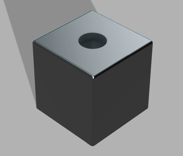
Button Stand

IMU Holder
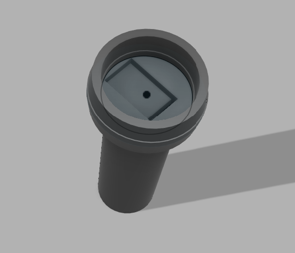
Microphone Stand