Results
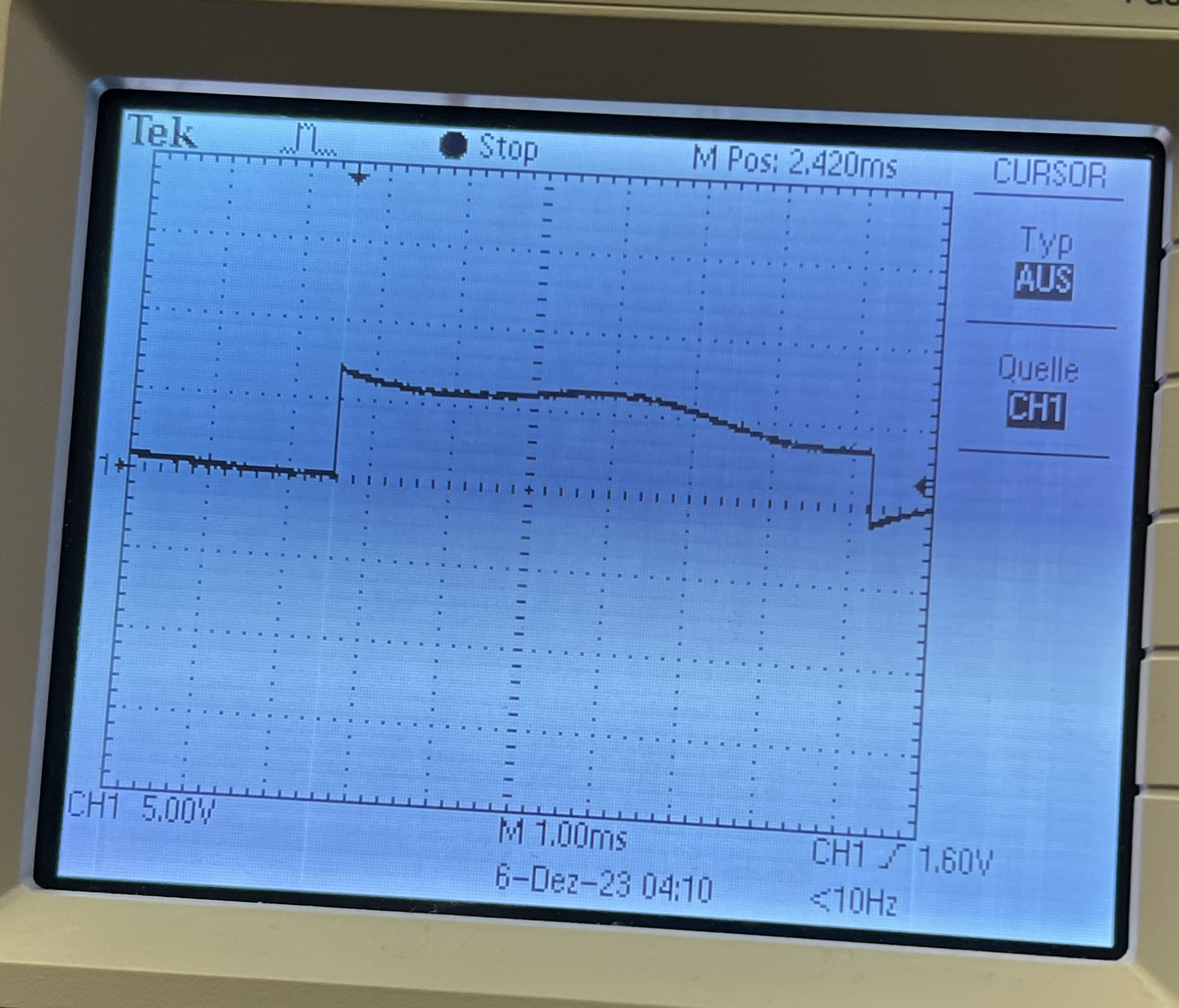
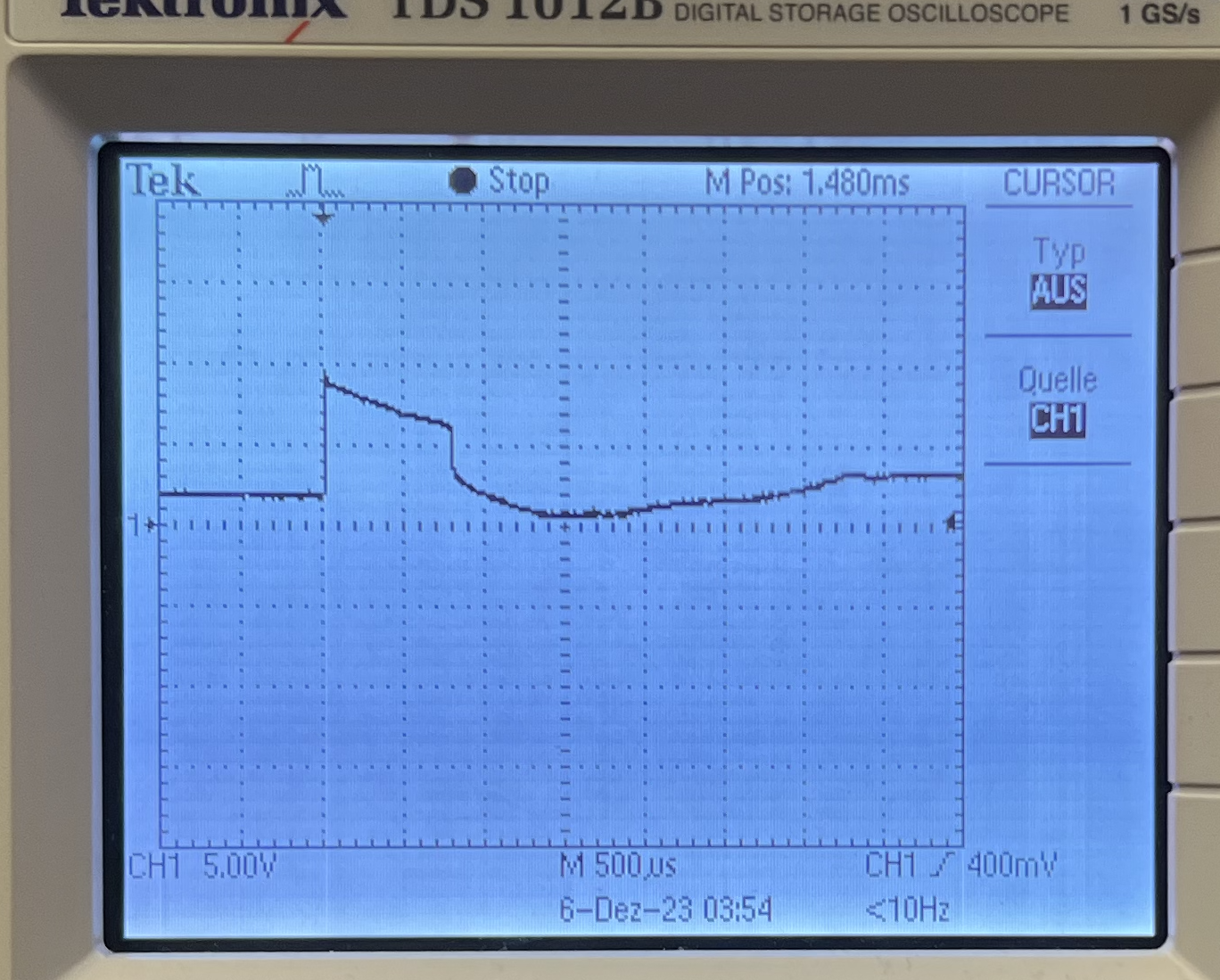
Given the fact that we had lots of modules within our project we started by testing each one before integrating. This made it easier to debug any issues and narrow down where fixes needed to be made. We first verify the LCD by physically verifing if it was displaying correctly. We then moved onto verifying and validating that the RF receiver was properly reading signals from the wireless remote. We set up a simple circuit with LEDs to show whether each pin was outputting high or low as we sent it button presses. Once we validated this we moved onto testing the gesture sensor by integrating it with the LCD screen we used. The LCD screen would display the direction that each hand gesture was registered as. We finally moved onto testing and debugging the stepper motor and its driver. This part was the most challenging portion to develop as it required figuring out the pinout to the driver board using an RP2040 and how to modify Hunter's PIO stepper driver. This required a lot of debugging on the hardware side as we checked the pinouts using a multimeter to verify that the correct order was used. During this process we also realized that we were not providing enough electrical power to the driver board/motor. On the software side of debugging we spent a lot of time figuring out the proper sequence of activating the motor coils to generate smooth steps/rotations. We also had to spend a lot of time figuring out the ideal rotation rate for the motor as there is a limit to large of an acceleration the motor can physically handle. We finished up motor bringup by writing code that would rotate the motor 90 degrees (50 steps) only. This was because we had 4 utensils on our carousel.
Once we finished debugging the motor we moved onto integrating all of the sensors and motor together. At this point we wrote up code that included logic for processing the sensor inputs and rotated the motor accordingly. After integrating all of the modules together we started to see some issues with jittering in the motor rotation again. We also noticed that the motor was having trouble rotating in the counter clockwise direction after integration. To solve this issue we worked on debugging our code to ensure there were no problems with instructions being sent while the motor is already rotating. We were able to fix this issue to an extent although the motor rotation was not as smooth as originally tested. We believe that this may be due to some timing issues with sensor readings affecting the motor instructions. All in all, we were able to successfully integrate a working system with a few minor flaws along the way. For the sake of building a prototype product for this project we believe it was quite successful as it proved that automating a kitchen utensil carousel with gestures is feasible. We believe that the next steps from here would be to use a larger power supply, re-integrate the motor with the original V1 design, and smoothen out the motor rotation.


Lessons Learned
There were a couple of significant lessons learned throughout the process of prototyping, designing, developing, and testing our project. One of the first issues that came up was with how much power being drawn from the RP2040. We noticed this first when we were testing different modules of our project before integrating them all together. We saw this happening while doing initial bringup of a 16X32 LED panel that we wanted to originally use as a status indicator for the user. However we quickly realized that it required a lot more current than the RP2040 could handle. Since we already decided that the stepper motor would require its own power supply we decided to just cut the use of the 16X32 LED panel. If we had a higher power dedicated power supply and power distribution circuit this would have been more feasible. Another issue we ran into is the fact that the stepper motor driver board we selected was not designed to be able to handle more than 1.2A continuously. It was able to handle ~3A at peaks that lasted around 20 milliseconds. This seriously throttled how much power and torque the stepper motor could output. This was a mistake in our component selection as we did not read the documentation enough before purchasing the part. By the time we realized this it was already too close to the deadline of the final demo. Lastly, this issue with the driver board led to our final issue which was also due to the lack of power in the bench top power supply. Stepper motor driver boards tend to be designed to input a higher voltage (~12-24V) while outputting ~3-6V. The power supply we used in the lab had a maximum voltage of around 6-7V at ~1.5A. This made it very hard to give the stepper motor enough power to exert maximum torque as well. This ended up making it so our carousel in the V1 design would not rotate as there was not enough torque. Thus, we redesigned to make a smaller scale proof of concept with our V2 design. The lack of electrical power also made the stepper motor jitter a lot while rotating. As a result, we learned that we need to read through the datasheets of all of our components more closely and make sure that our power supplies can support the power requirements of our projects in the future.
Conclusions
Our final design was a little rigid over the smoothness that we would have liked. The turning of the motor could have been much smoother and be a bit more controlled, but given that we were fixing it right up to the presenation, we were fairly happy with the result. If we could change things, we would have ordered an adapted to be able to pull current from an outlet over the power supply as we would have not had the current issue that we were experiencing. If that was the case, we could have also ran with the original fabricated design and have had a closer to market type of design.
We were not far from meeting commerical appliance standands. We would just need to implement an power supply module to be pluggable into an common outlet. The wattage draw on the plug would meet standards. Outside that, we would only need to construct housing for the electrical equipement, add a user guide, and have warnings about the electricl interior to the product. If we desired, we could possibly apply for a patent for the mechanical aspect, but we feel it may not be novel enough for one. There does not seem to be other kinds of patents for this kind of product outside very specific, non-automatic designs. However, our project is different enough that those should not interfere with our design.
We would like to acknowledge and thank all of the help and support from Hunter-Adams and Bruce Land in building this project. We did utilize Hunters Code as a framework and support for the stepper motor and controller. We utilized Adafruits library for the APDS9960 digital proximity, written by Dean Miller in the UNO R3. We also utilized library code from ARDUINO.cc for the LCD.
