Initial Concept
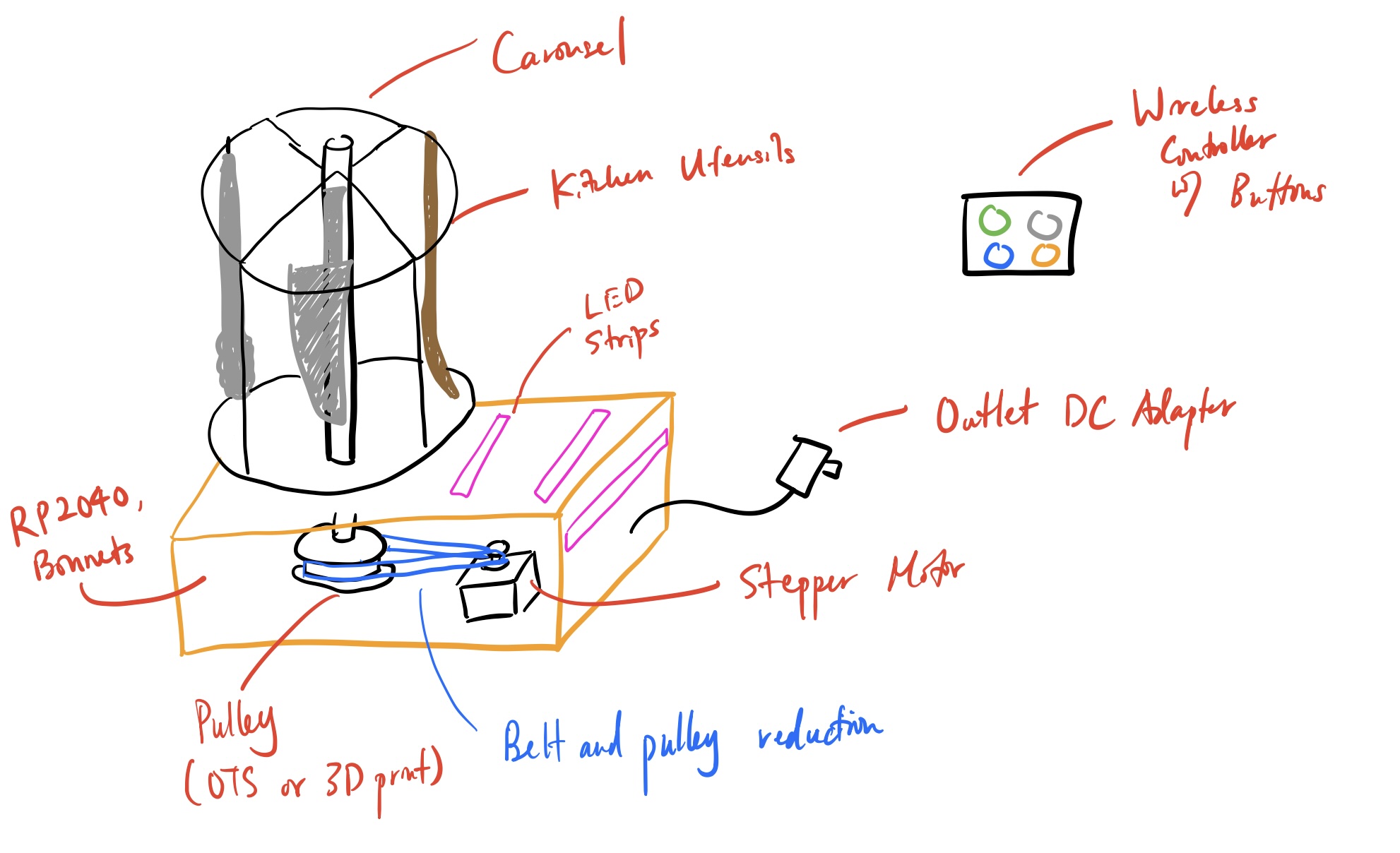
Our initial idea started with the desire to build a physical product that is both practical and unique. This started from brainstorming ideas about what inconveniences we have in our own lives that could be solved by building something with the RP2040. We also combined ideas on methods of actuation and/or sensing that we would want to work on while building our product. Over multiple discussions we narrowed it down to wanting to build a product that automates a part of our lives. Given the budget and time constraint we finally chose to build an automated kitchen utensil carousel that would be actuated with a motor. We also wanted to integrate a human interface through the use of a gesture sensor and wireless remote. We considered including a microphone to process voice commands as well, but cut this feature out as we thought it would be challenging to accomplish within 3-4 weeks. We believed that this was a perfect mix of challenging software and hardware implementation and integration that would lead to a practical and useful product. The image below shows an initial sketch of how the kitchen carousel should look.
Component Selection
After deciding on the project we wanted to build we had to select components to purchase or find to build it. We were given a budget of $125 where $25 of that would be covered by the course. Since we knew that we would be rotating the carousel we chose to use a motor to actuate the rotation. Specifics on the motor selection can be found in the Motor Selection subsection below. We chose to look at Adafruit for purchasing a off the shelf (OTS) electrical hardware as they are a trusted source with decent documentation. Furthermore, to actuate a motor a driver board is required so we chose to look at options that existed on Adafruit. From looking on their website we found that a compatible driver board was the TB6612 breakout board because it had the proper pinout for a 2 pole stepper motor. We also looked on Adafruit for sensors and found an RF receiver, wireless remote, and gesture sensor. Specifically, we chose the RF receiver because it was able to work with a generic wireless remote that emitted 315 MHz signals. The RF receiver we used was already configured with circuitry that output a simple high or low signal from 4 pins. The gesture sensor we chose was an Adafruit APDS9960 sensor. This was used because it also had integrated circuitry to help process hand gestures and output whether it was a left or right swipe.
For mechanical OTS components parts were found around the lab, Rapid Prototyping Lab, and McMaster Carr. Nuts and bolts were purchased on McMaster Carr or found in the lab. We also found a lazy susan from a previous student's project in the lab as well. The Rapid Prototyping Lab's scrap pile was used to save cost on fabricating the parts in our project.
As a result, our total Bill of Materials (BOM) cost turned out to be $52.59 which was much lower than the maximum budget allowed. The BOM can be found below.
Mechanical Design
Motor Selection
The main mechanical hand calculation that needed to be considered for this project was selecting the motor and potential gear ratio between the motor and carousel. Some common motor options for low power/torque applications include a servo, standard DC motor, or stepper motor. We decided to use a stepper motor over the other options for three reasons. Firstly, stepper motors have a wide variety of powers and sizes readily available as they are used for a lot of CNC gantry systems. Secondly, although stepper motors do not have a closed loop position feedback system, they are designed to rotate in steps. Each step is equivalent to a certain amount of angular rotation in degrees. This is specified in the datasheet. Lastly, using a standard DC motor would require a potentiometer or encoder with a closed feedback loop to rotate the motor to a specific angle. For the sake of easily controlling the positional accuracy of the carousel we chose to use a stepper motor. Rotational speed of the carousel was not an important factor.
As mentioned earlier in the Component Selection section we decided to look for electrical OTS components off of Adafruit as it was a reliable source. Within Adafruit there were two stepper motor size options. They were the NEMA 17 and NEMA 23 sizes. NEMA stepper motor numbers correspond to their form factor, but the NEMA 17 motor only had a maximum holding torque of 1.77 lbin. This was not enough torque to have any sort of safety margin. Therefore, the NEMA 23 motor was selected as it had a maximum holding torque of around 8.75 lbin (0.9886 Nm). To validate that the motor would have enough torque to rotate the carousel on the lazy susan a simple momentum balance was used. The equations below show the math that was used to do so.
The moment of inertia (I) was derived by generating a 3D CAD model of the carousel and lazy susan assembly with a gear on it. Using this value and calculating the rotational acceleration provides a good idea about whether the motor has enough torque. In the case that it does not a gear reduction can be used as well. With the size of our carousel the stepper motor there was more than enough torque to rotate it with a 1:1 gear ratio as the rotational acceleration is very high.
CAD
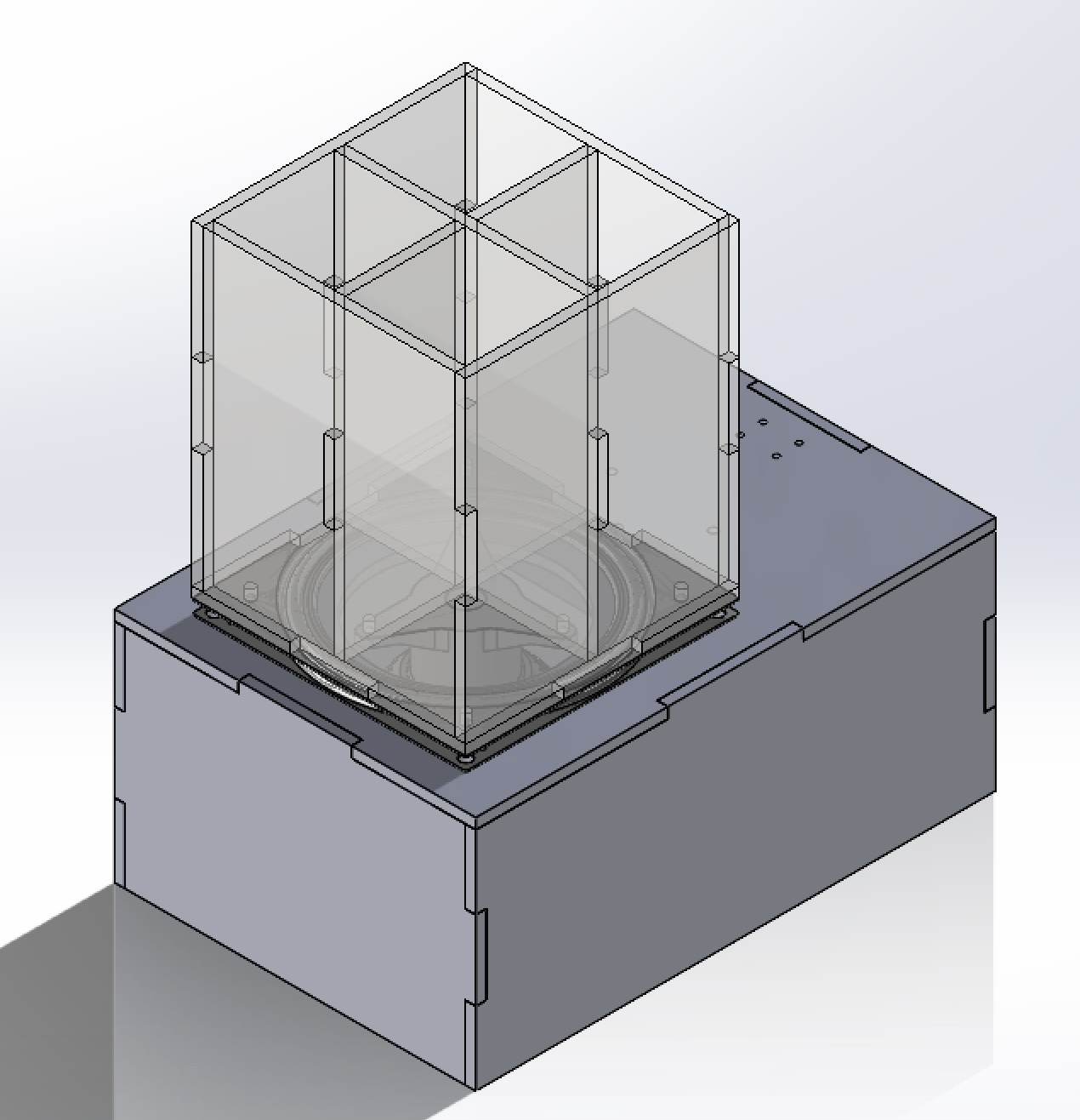
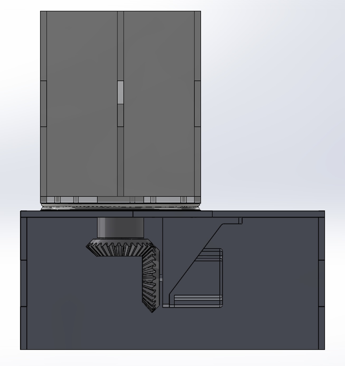
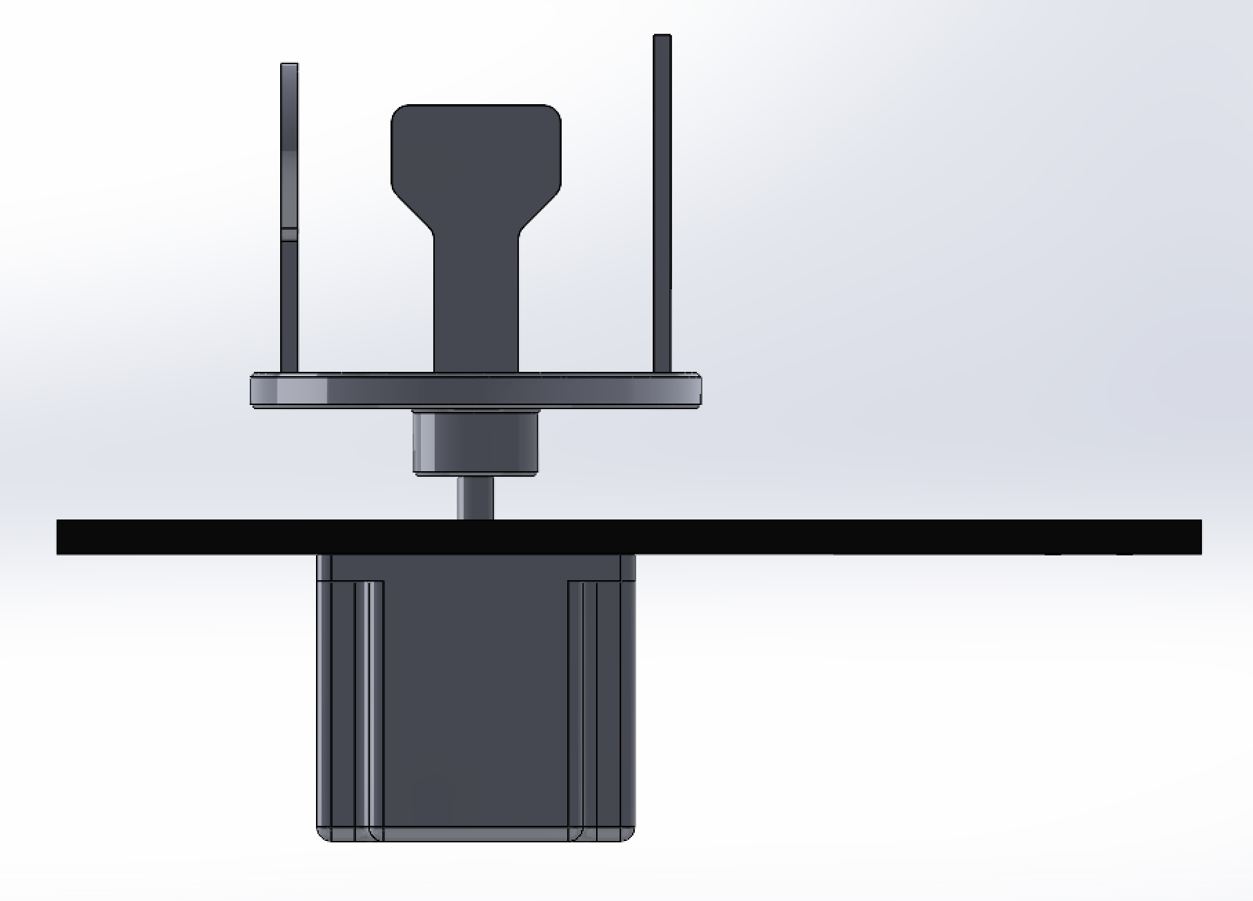
The images below show the version 1 CAD models of our project's mechanical design. It is mostly constructed with 6mm and 3mm acrylic laser cut sheets. The second image shows a side view of the assembly where there is a stepper motor that powers the carousel using 90 degree bevel gears. The bevel gears were also designed to integrate nicely with the motor and carousel. The stepper motor's mount and the two bevel gears were 3D printed using high strength filament on a Markforged printer. This was done to maximize the structural stiffness of the assembly to prevent any unexpected issues with the gear teeth meshing. The gesture sensor's mounting holes are also on the main plate.
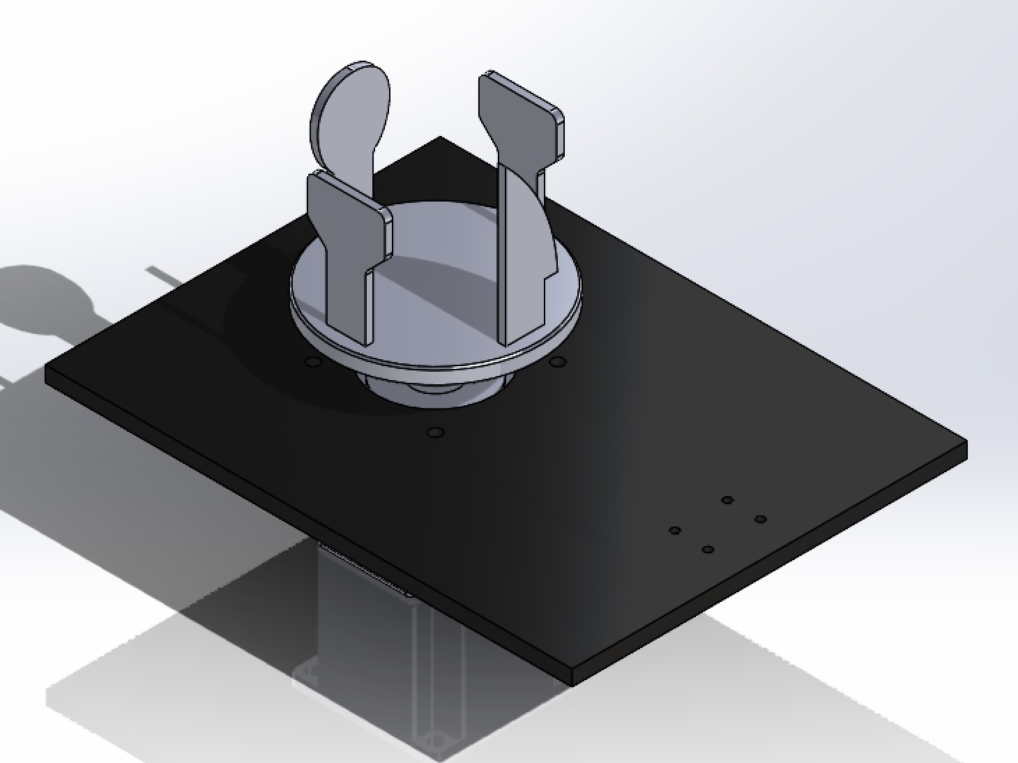
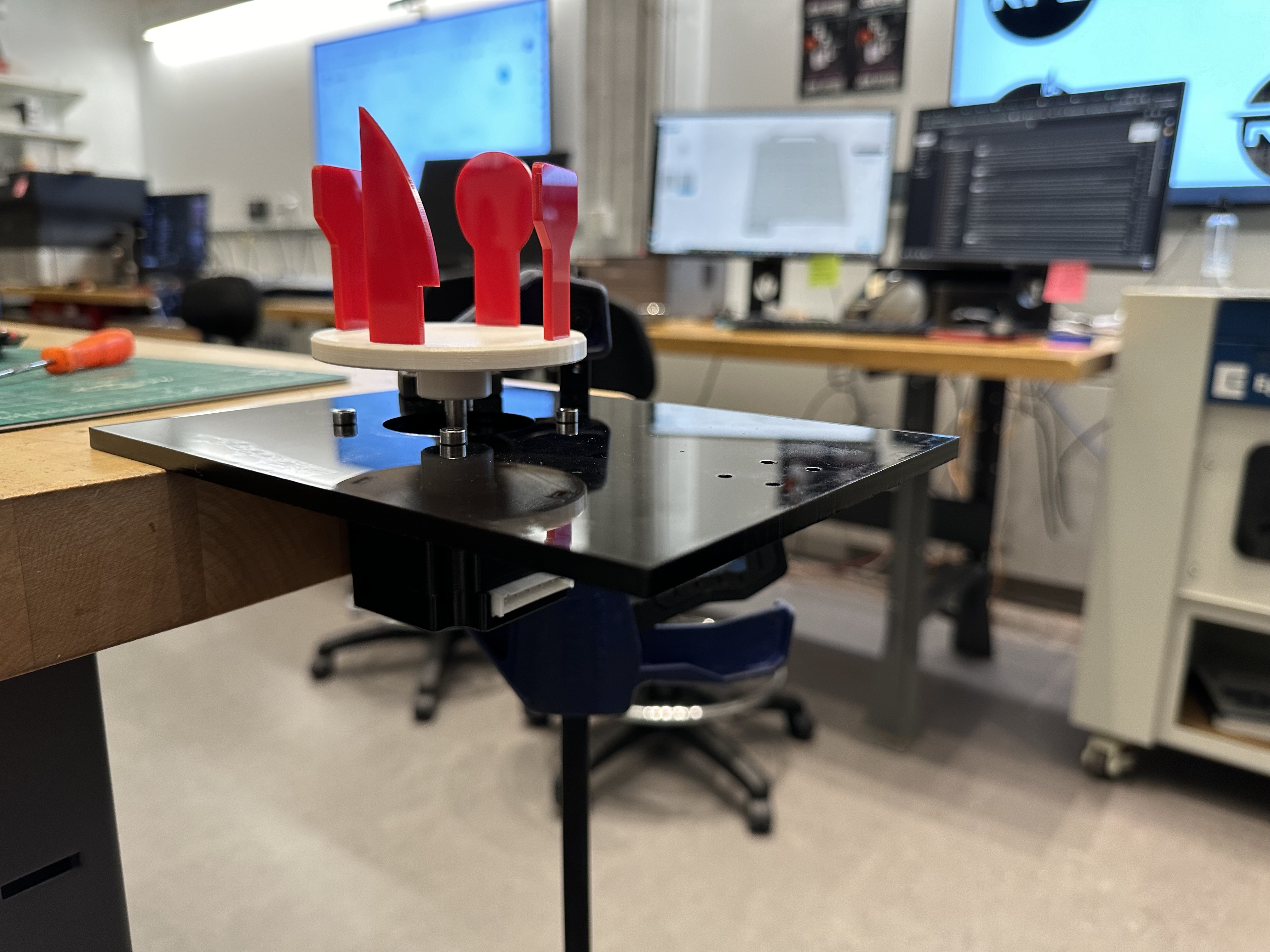
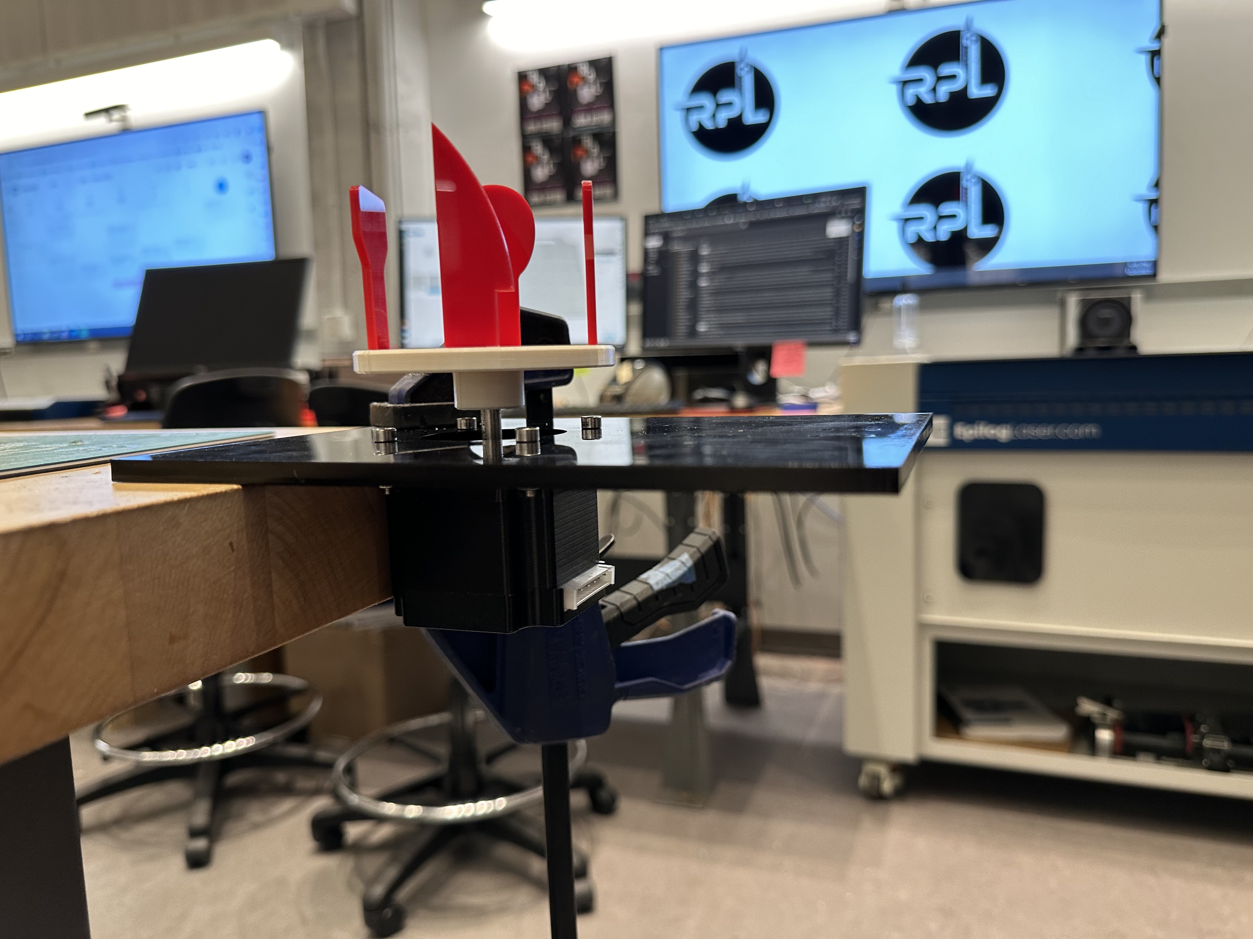
The images below show the version 2 CAD models of our project's mechanical design. The reason for having a second version is discussed in the Performance page. This version is a simplified proof of concept of the original full size. In this case the motor is directly attached to a smaller scale carousel and laser cut "utensils" are inserted. The gesture sensor is again intended to bolt onto the main acrylic plate. In both versions of the mechanical design the electrical circuitry is planned to be placed on the side of the fixture as everything is connected through a breadboard.
Fabrication & Assembly
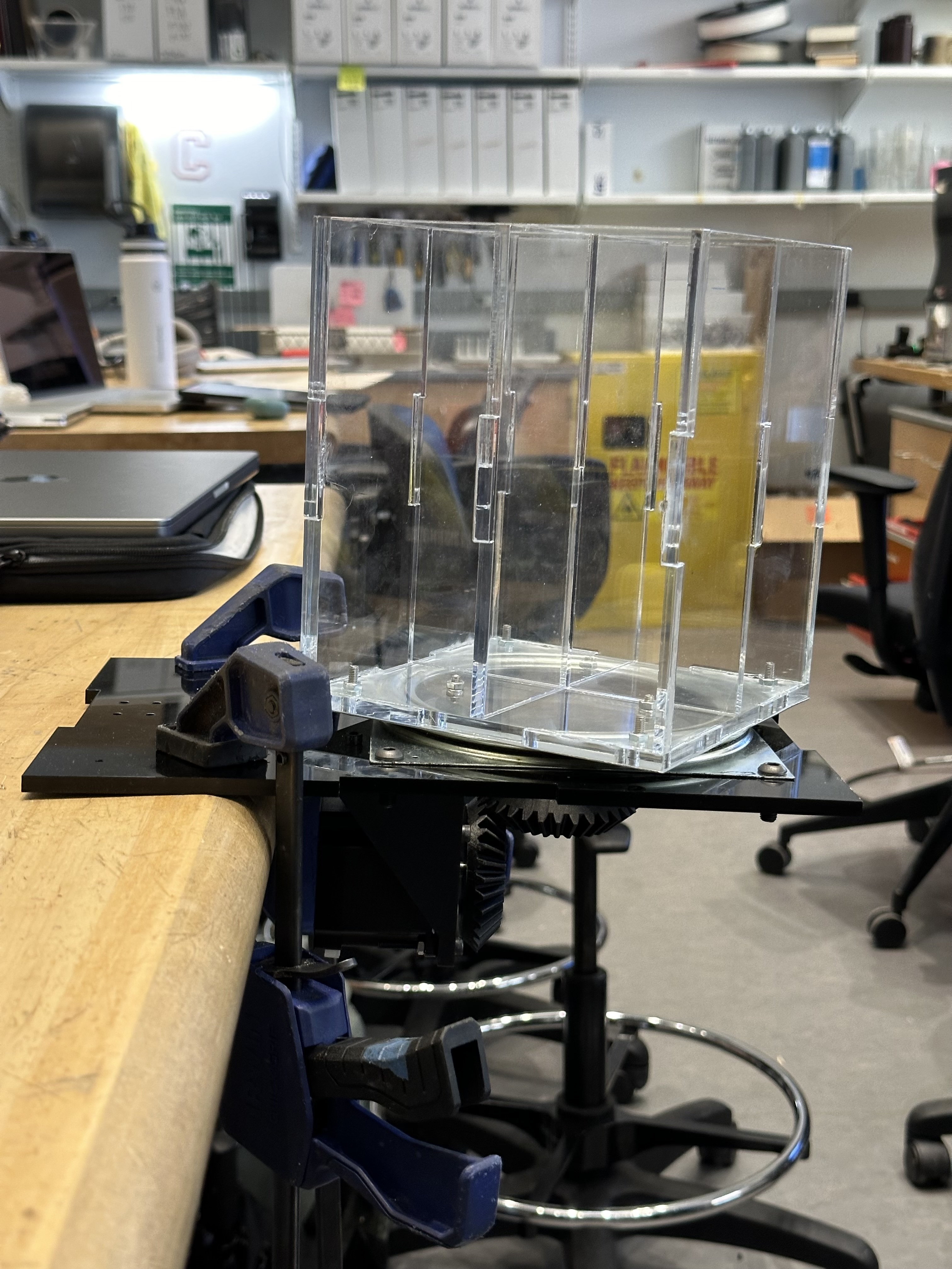
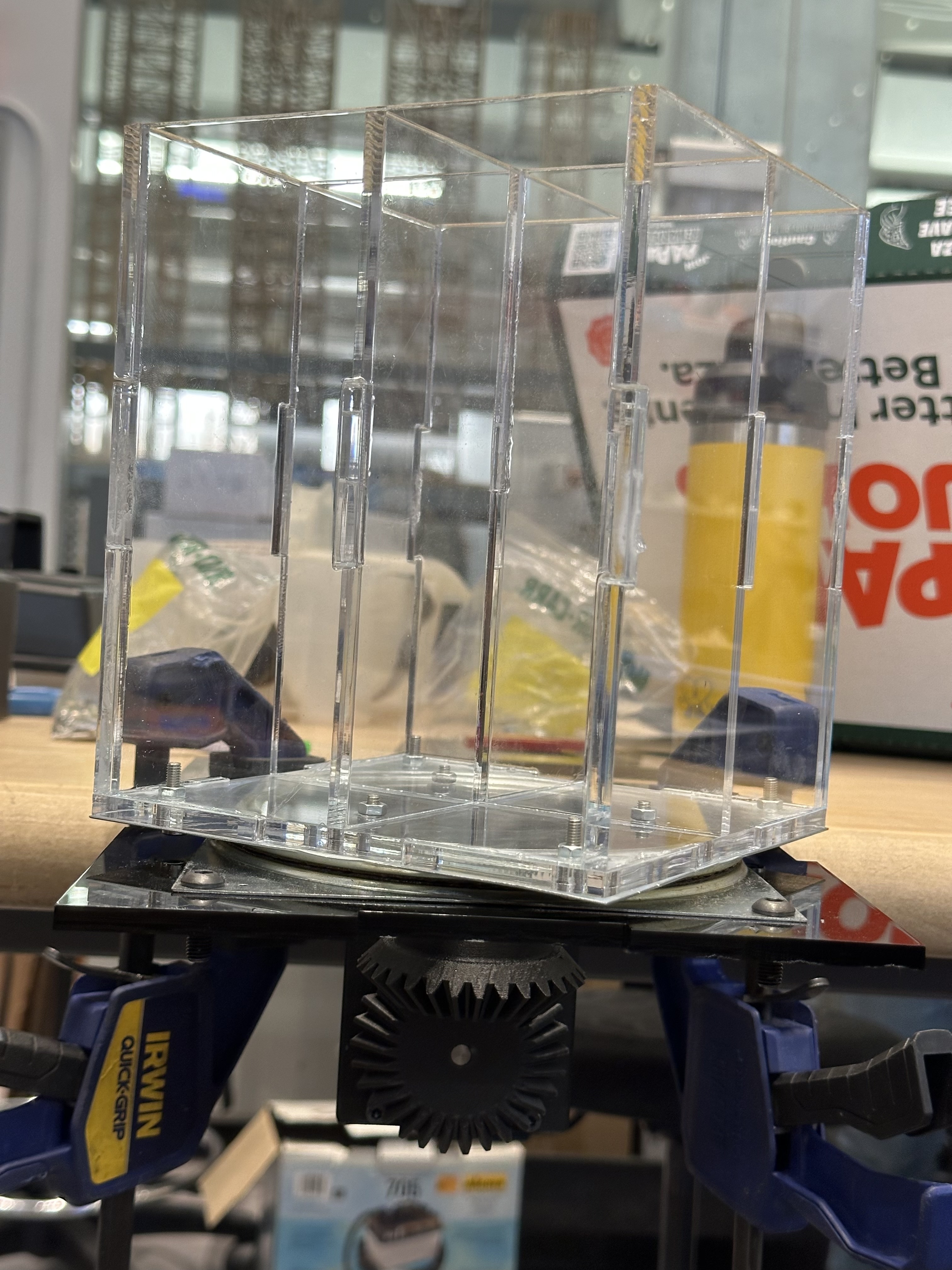
All designed components were laser cut and 3D printed in the Rapid Prototyping Lab. Assembly of the parts consisted of M4X16 nuts and bolts along with some super glue to constrain acrylic sheets. There were no issues with the assembly process as all hardware components were easy to reach with wrenches and allen wrenches. Proper tolerances were accounted for in the 3D printed components to allow for press fits and clearance fits.
Schematic Layout
The following images show our circuit design used in our project as well all of the commponents utilized. Initially it was planned for the UNO to handle the RF reciever and the PICO to handle the gesture sensor,but due to time consumed on trying to fix the motor, this was swapped to use Adafruit's library for the sensor via the arduino.
One may notice on the schematic that we hard wire the UNO to the PICO for I/O communcation. This way raise a red flag as the UNO should be operating at a logic level of 5V and the PICO at 3.3V which would cause over voltage issues if they directly connect. Despite this reported operation, the UNO was operating at 3.3V and was verified by many measurements. We believe that the power supply module of it was faulty or was stepping the voltage level down internally. This allowed us to have direct communcation between the boards. Had this not been the case. Would would have had to utilize four bi-direction level shifts to ensure correct voltage levels between the boards
Electrical Layout.
Raspberry Pi Pico (RP2040)
Elegoo r3 uno
Simple RF T4 Receiver - 315MHz Toggle Type. Paired with Keyfob 4-Button RF Remote Control - 315MHz.
Adafruit APDS9960 Sensor
SUNFOUNDER LCD1602
