VGA Circuit Design
The game was displayed on a monitor connected to the Raspberry Pi Pico through a Video Graphics Array (VGA) connector, which uses analog signals to draw to the screen. The adapter usually has 15 pins, but we only needed to utilize six to draw to the screen: ground, HSync, VSync, red, green, and blue data signals are sufficient. The HSync and VSync signals control how horizontal lines of pixels at each vertical index are drawn, and we utilized the vga256 graphics library to produce an eight-bit color display, to achieve the necessary color resolution to draw the face of Sir Issac Newton. The voltage level on the VGA color connections determine the intensity of the color that is displayed on the screen (with a peak-to-peak of 0.7V), and the Pico GPIO pins are 3.3V when high, we needed to produce a voltage divider that could generate signals within the 0.7V range at high resolution. The VGA adapter has about 75 Ohm resistance, so our voltage divider should account for this and choose values that will divide the initial GPIO voltage by about four or five. Since we are using eight bits for color, one color (blue) will have to be underprivileged in the sense that it will only be able to use two bits to set the color, while the other colors can use 3. Since shades of blue are less discernible to the eye, this color is chosen to use only two bits. So red and green will use two GPIOs, and blue will use two. Each GPIO is weighted differently using resistors that divide the voltage, so we can cover the whole range of 0 to 0.7V. Below is the voltage divider circuit that we used.
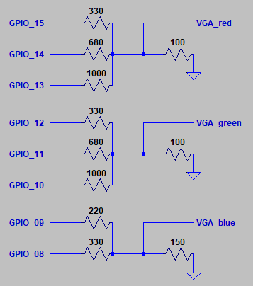
Schematic of 8-bit VGA Circuit
From Bruce Land's 256-color VGA display project on the Pico and RP 2040 project. See Appendix D for full citation.
Due to available resistors having inexact resistances and the desired circuit simplicity, if the 75 Ohm VGA resistance is to be trusted, the red and green VGA input voltages will range from 0 to 0.63V, while the blue will range from 0 to 0.9V. The GPIO pins with larger resistor values will have less of an impact on the actual signal voltage, so we can cover the range in eight relatively even increments for red and green, and four for blue. However, due to some error, the image display was appearing much more cyan and magenta than expected. We investigated the voltage on the green GPIO, used a multimeter to test the resistor and wires, and were unable to find anything out of the ordinary. We eventually tried replacing entire components of the circuit, such as the resistors in the green data circuit and the wires, and were able to determine the error was a faulty MtF green wire, which was not making a connection on the female side, and evaded out multimeter testing due to the available wire exposure on the side of the connector.
We used an online image editor to construct the sprites with proper pixel dimensions, and saved them with 8-bit/channel RGBA format, as this was the minimum allowable resolution from the software. We used a simple Python script, named PNG_to_h_converter.py in the project repository, and the PIL Image library to convert these images to use proper 8-bit colors.

Key Segment of Converter Script
Here, we set any alpha pixels to black, changing from white after we noticed that the background is black, and constructed a new image with pixel values RRRGGGBB, where the most significant bits of each color are used to represent that color in lower resolution. With the sprites created, and the VGA hardware configured, we were ready to begin working on implementing the game.