Controller Design
Acknowledgment: The design for this circuit is heavily derived from Nick Bild’s gesture-controlled Pong game on the Pico. See Appendix D for full citation.

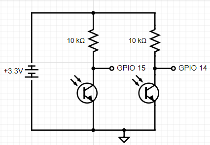
Circuit Diagram of the Gesture Controller Circuit
The gesture controller circuit uses two pairs of IR LEDs and IR phototransistors to detect the position of the player’s hand. To do this, the circuit below turns on the two IR LEDs in the breadboard diagram below using a bench power supply set to 2.5V and turns on the two IR LED phototransistors using the Pico’s 3.3V output pin. The controller circuit rests in a housing with mirrors affixed to the top so that the IR light emitted from each LED can be reflected back down to the respective phototransistor, such that the phototransistor reads when this beam of light is broken. When the player’s hand moves right and breaks the beam of the right LED-phototransistor pair, they will signal to move the avatar to the right, and when their hand moves left and breaks the beam of the left LED-phototransistor pair, they will signal to move the avatar to the left. The light signal received by the phototransistors is then wired to the selected GPIO pins to connect the input to the Pico so that it can control the player’s avatar in the game. The result is a rather intuitive game controller that requires no involved or precise hand or finger motion (grasping, tapping, directing, etc.) and is tolerant of many common afflictions of the hands and joints such as hand tremors and joint weakness.

Breadboard Diagram of the Gesture Controller Circuit
*Note for Clarity: On both sides, the IR Phototransistors, the GPIO pin wire, and 10 kΩ resistor are all connected to the same column (node). This is slightly unclear in the image due to space constraints.
Because we sourced the 940nm IR LEDs and phototransistors from the Electronics Laboratory, the datasheets of the components were difficult to find as the names were not listed on the bins or on the components themselves. Nevertheless, we attempted to identify them using their key characteristics (turn-on voltage, diameter in mm, wavelength, shape, and color) and found datasheets for components that were the same in all of these respects, which are enclosed in Appendix D.
This circuit was tested independently of the Pico to ensure that no damage was done to the board in case of a voltage spike (while this did not occur and no components were damaged during testing, we felt that this was an appropriate precaution to take). Since the bench power supplies allow for two independent power outputs (one from 0 to 6V and one from -20 to 20V), we were able to use the power supply to supply the appropriate amount of power to both sides of the controller circuit (2.5V to the LEDs, and 3.3V to the phototransistors). To test that the LEDs were on, we used cameras without IR filters (iPhone cameras have these, so they cannot detect when the LEDs are on), touching the LEDs to feel their warmth (because they never even approached painful temperatures regardless of wiring when supplied with up to 6V from the power supply, so we determined this was safe to do) and the current reading of the power supply (typically, the LEDs turned on when they received over 15-17 mA of current). By using an oscilloscope to probe the circuit using the wires to the GPIO pins, we were able to trace the output of the phototransistors to understand how the circuit was working. Initially, we found that the phototransistors were not able to detect the light from the LED because there was not sufficient diffusion: the phototransistors would have to detect a very focused beam of light because of the rounded head of the IR LED. However, filing down the head of the LED did not fix this issue, so we switched from a 5mm diameter phototransistor to a 3mm diameter phototransistor (while keeping the IR LEDs at a 5mm diameter) to further decrease the accuracy needed to achieve a complete beam of light between the two components. This worked to establish a connection, but resulted in a shaky signal as the HelpingHands that we were using at the time were easily jolted by players’ movements and were generally unsteady, so to avoid this problem, we decided to create a fixed, stable housing for the controller. The video of final successful test of the controller circuit (including the housing, to be discussed below) can be found in Results.
The controller housing was designed in Onshape and printed using blue PLA filament. This controller housing holds both circuit breadboards at the bottom, and the angled lofts at the top of the housing ensure that the mirrors are affixed at the correct angle to reflect the light from the IR LEDs to the IR phototransistors. Images of the CAD model as well as the printed controller housing are shown below, but the model can be accessed at this link by users who possess an Onshape account. The model uses the position of the LED and phototransistor to calculate the appropriate angle for the lofts at the top of the controller housing so that the mirrors are affixed at the correct position, as shown in the images below. The housing also guarantees ample vertical space for the player to move their hand inside the housing to control the avatar, and the open sides make the controller more comfortable and easy to use.
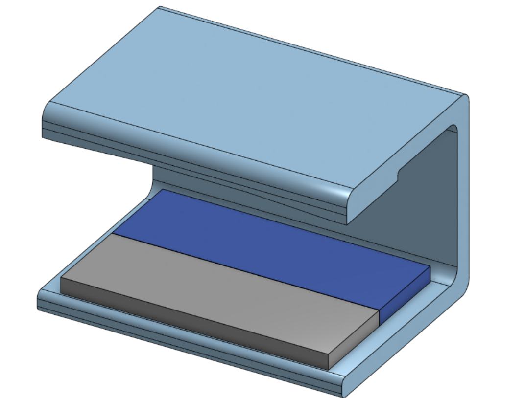
CAD Model of Gesture-Controller Housing from Onshape
*Note for Clarity: The gray and blue boxes on the base represent the locations of two breadboards used to house the controller circuit and VGA circuit (respectively), and are not a part of the housing.

Lofts of Controller Housing
This view of the CAD model shows the lofts to which the mirrors are affixed more clearly.
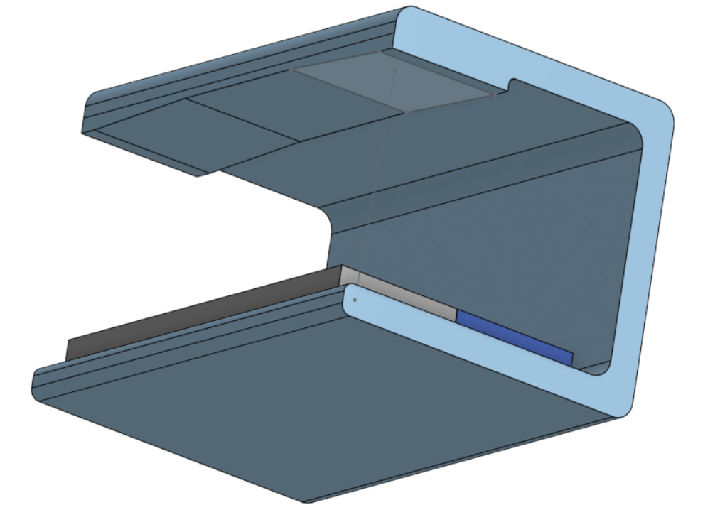
Lofts of Controller Housing: Angle Sketch
This view of the CAD model shows the sketch used to calculate the angle of the lofts using the positions of the IR LED and phototransistor pairs on the circuit.
[Thank you to Matthew Young (Cornell CoE MAE ‘24) for assisting in the design of the controller housing by recommending Onshape and (very patiently) teaching the features necessary to design the housing, as well as allowing the use of his 3D printer and filament to print the controller housing.]
Many ideas for expanding the functionality of the game (such as a menu or player shooting controls, further discussed in Conclusions) involved the idea of adding a third control, but we decided to not incorporate this idea due to its complexity. The circuit hardware is very scalable: we could simply add another LED-phototransistor pair to the circuit and the player would have to move their hand to a different position to shoot (perhaps place another breadboard between the existing two so that the player’s hand moves in a triangle throughout gameplay). But all versions of this implementation were very clunky and counter-intuitive for the player (the avatar’s motion is no longer following hand motion, easy to accidentally trigger shooting and stop movement, longer distance to move the hand for all controls) and deemed non-viable. We concluded that a more intricate controller circuit would be needed so that the player could alternate between a flat hand and a vertical hand to shoot (turning the hand does not require the same precision of movement as pinching or other gestures that could have signaled this, so this was the preferred choice of alternate gesture) to maintain the purpose of the control scheme, which we could not accomplish in the remaining time allotted for the project, but this could still be an interesting extension of the project.