Results
Oscilloscope Waveforms
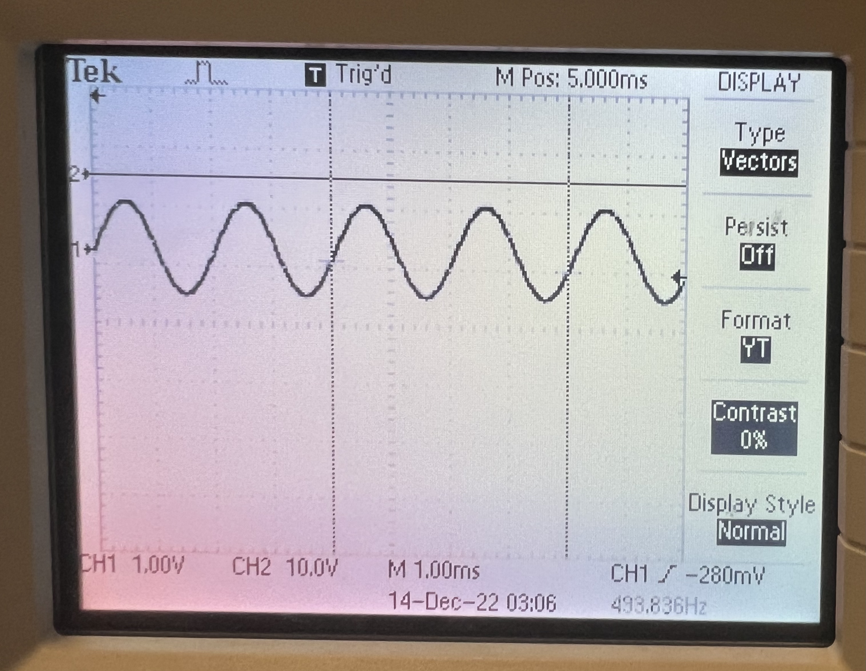
Sine
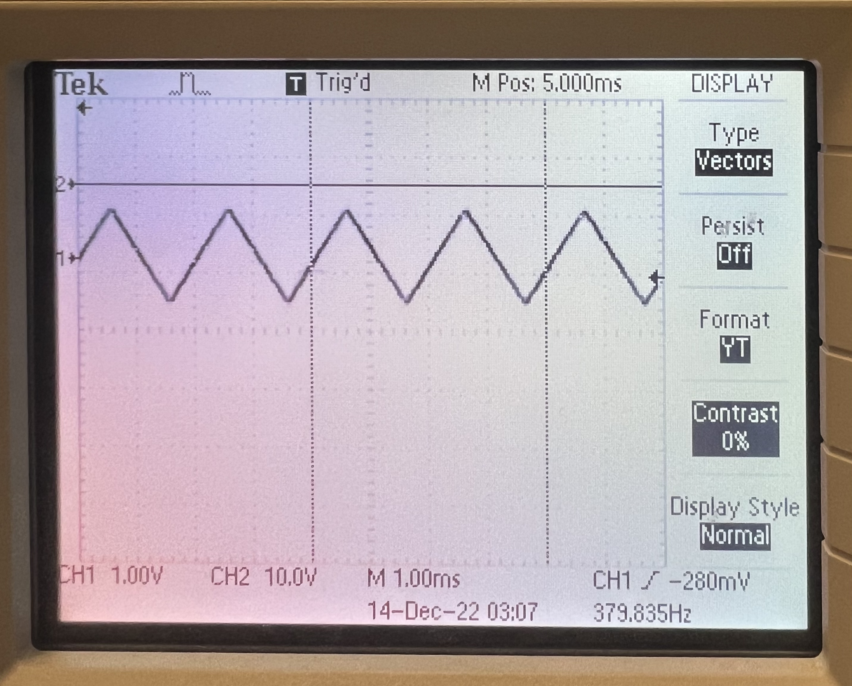
Triangle
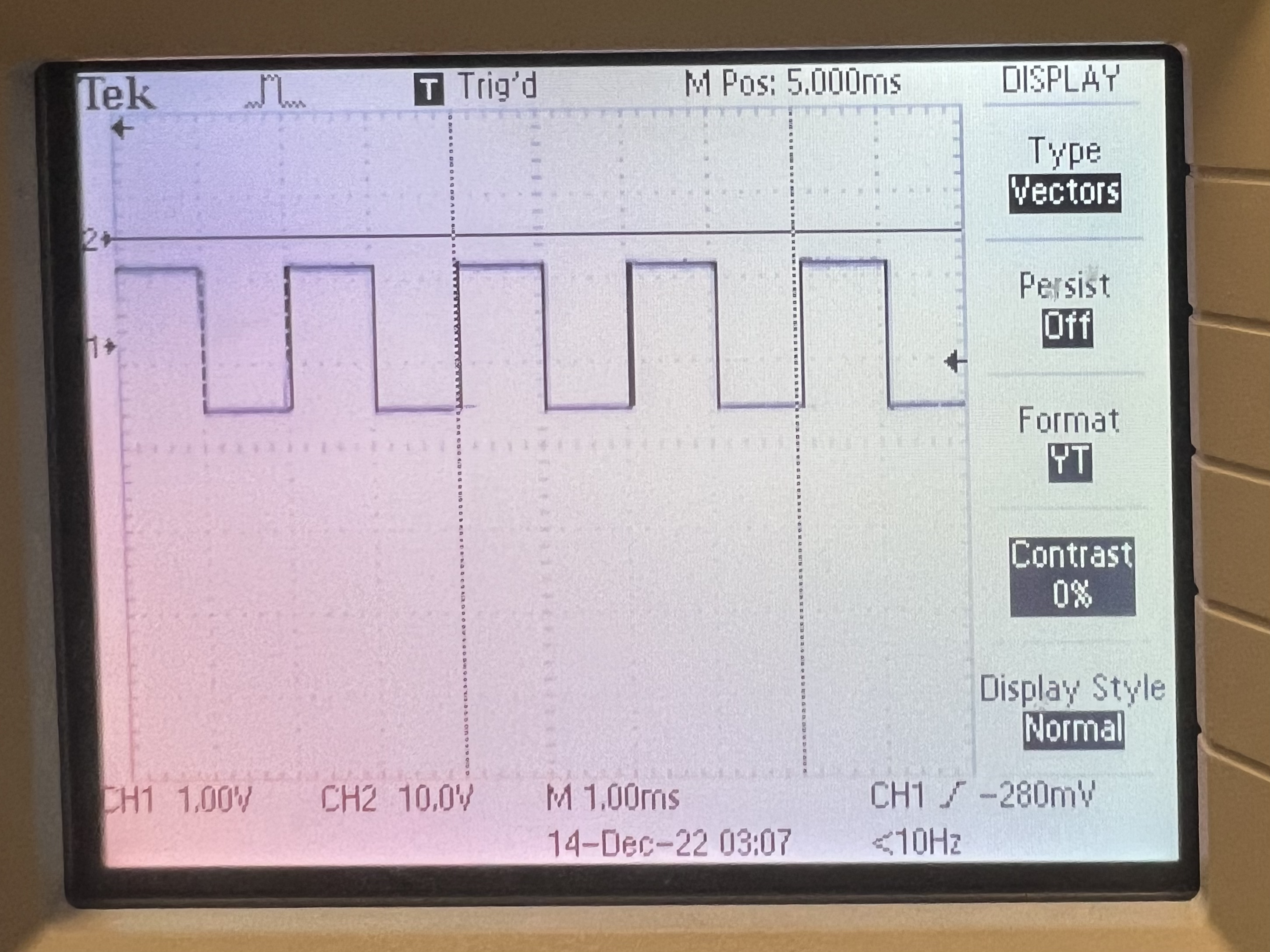
Square
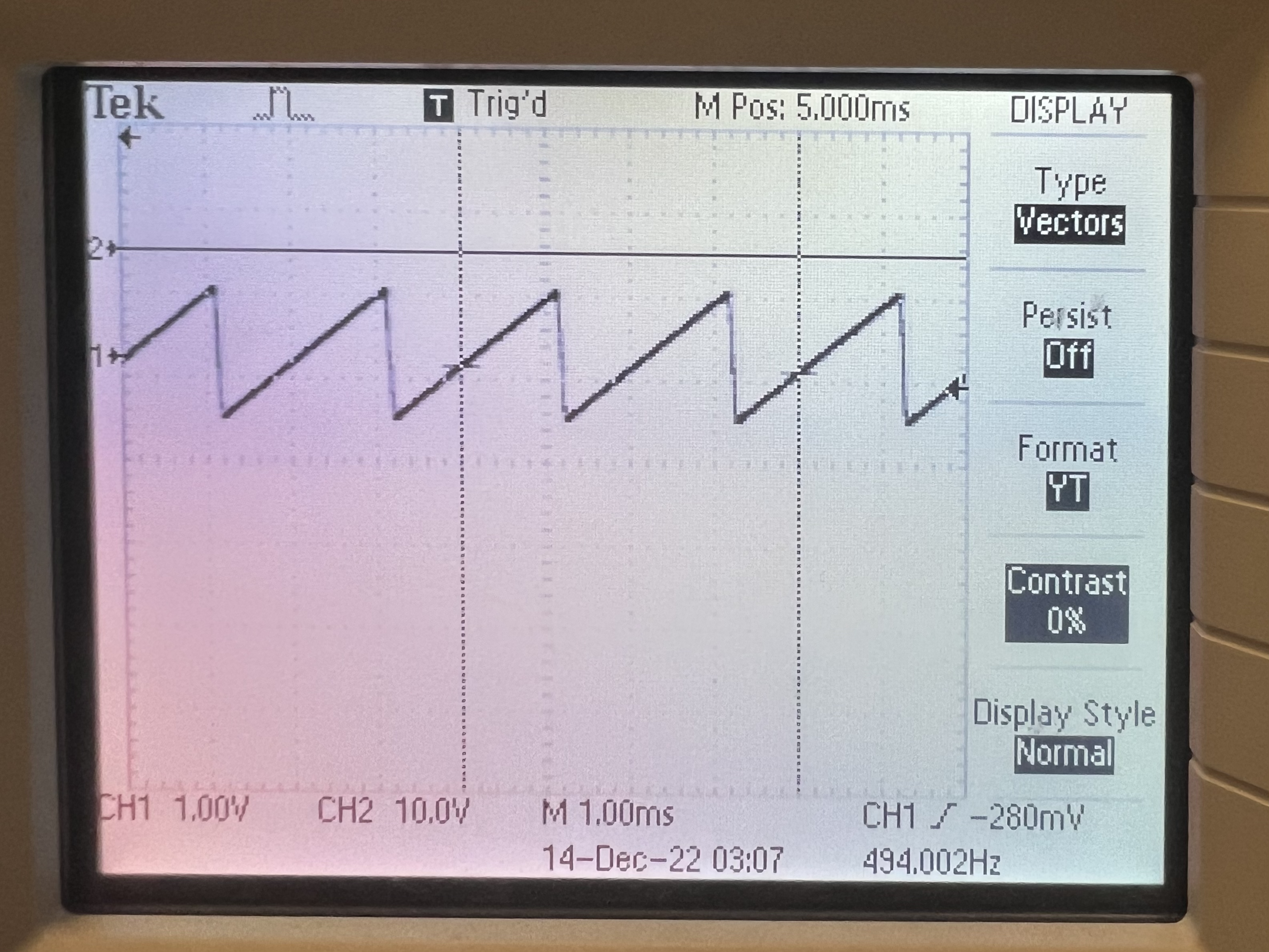
Sawtooth
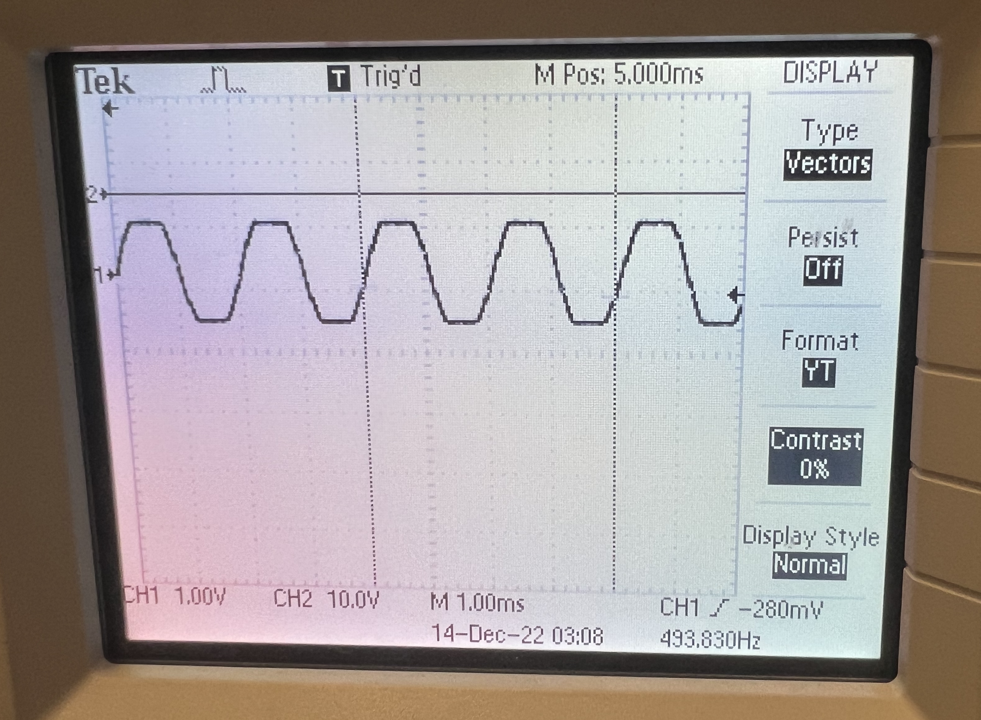
Filtered 1
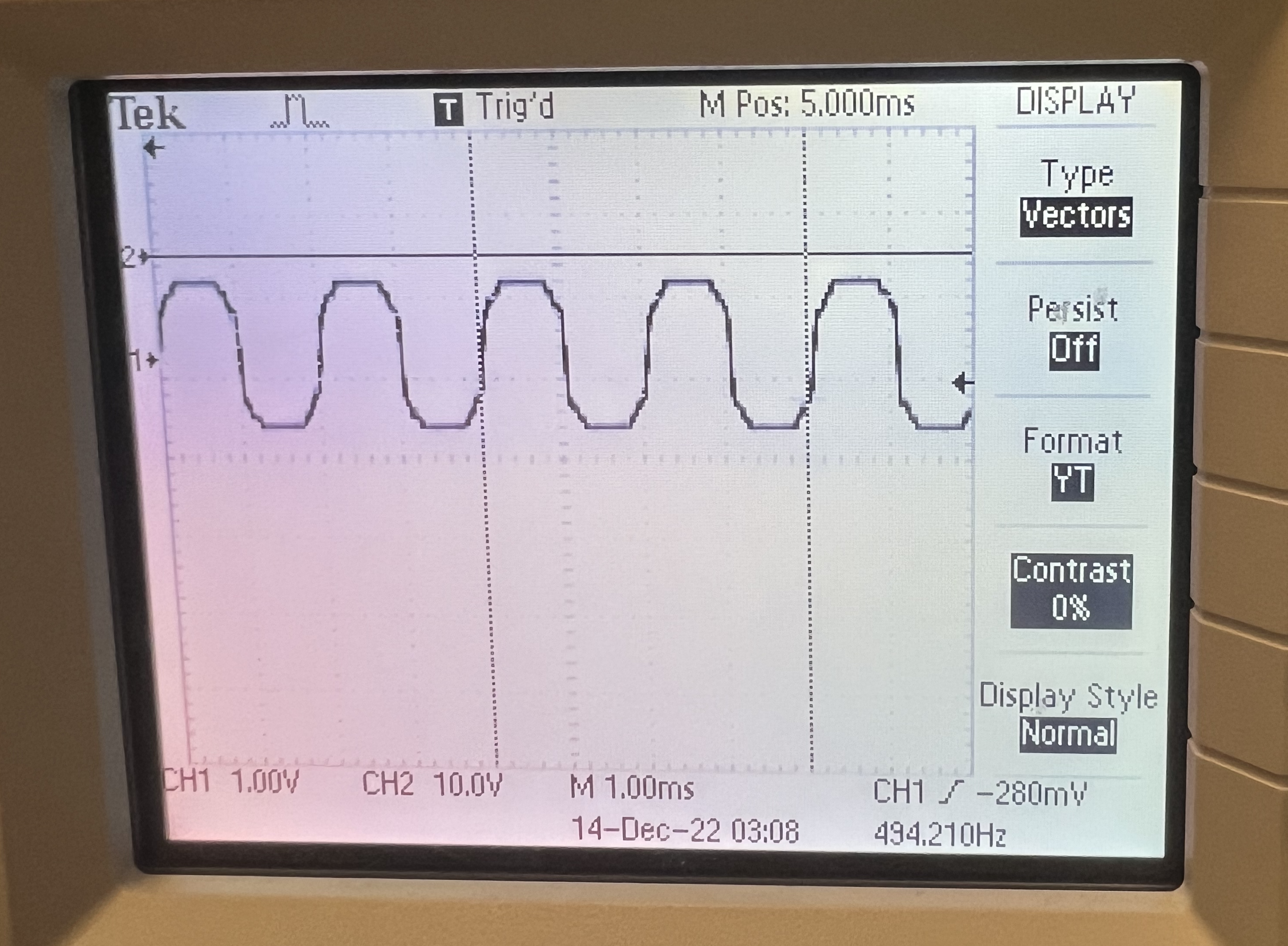
Filtered 2
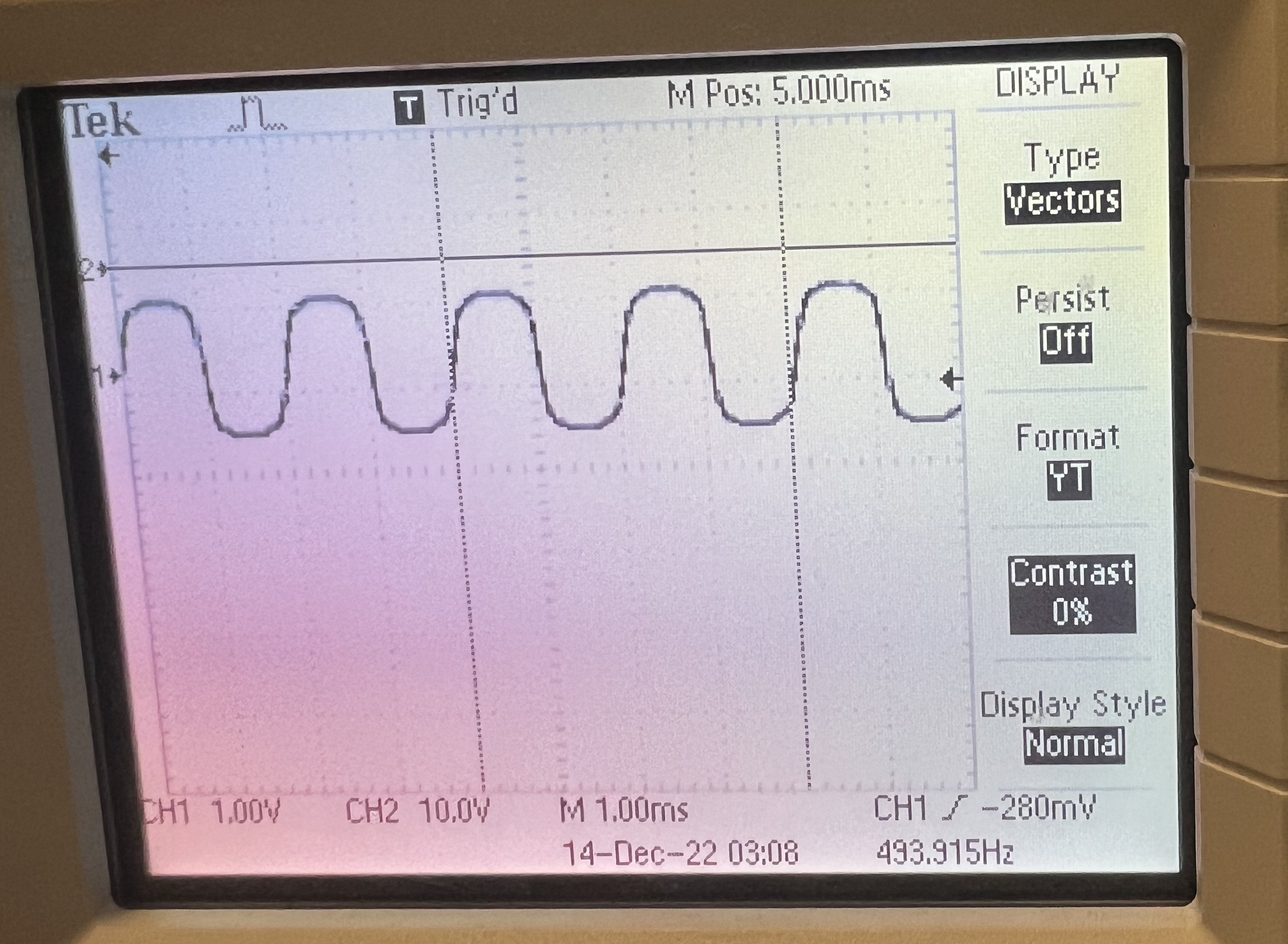
Filtered 3
Speed
We had interrupts on timers for the TFT screen updates and had it check if a new input value had been changed before refreshing part of the screen - like the button, rotary encoder, or potentiometer. This allowed for the capacitive touch to be more responsive, avoid unnecessary updates, and let other parts of the system, like the FFT, get more cycle time.
Moving the filtering calculations to an interrupt different from the DDS output helped the DDS interrupt meet its timing requirements. We polled the inputs regularly, but only updated values if there was a change.
Accuracy
Sampling rate timing requirements
We checked output wave timing by looking at the oscilloscope readings of the DAC. After adding in filter calculations we checked to make sure that the output waveform was still the same timing-wise as if we were outputting only a pure tone. We also used the oscilloscope to see if our filters were modifying the waveforms or not.
The different inputs were very accurate and allowed for instantaneous changes when pressing on the different keys on the capacitive touch sensor.
Discussion on user input + display info accuracy
We wrote out code such that all changes in settings would be reflected real-time in the output waveform. We thought it would be much more interesting and intuitive if changes had an instant impact rather than relying on some sort of reset button or save setting button before the changes would take place. The tradeoff for this is that depending on what settings are being changed, unexpected results may occur due to the sheer number of parameters. However, this allowed for the display to be accurate to what was being output at any time.
Safety
We created a cardboard frame around the Pi Pico, TFT display, and button inputs to isolate all the wiring from the area where people would be moving and pressing buttons to avoid accidental short circuits. We also hot glued all components and large groups of wiring on the TFT and capacitive touch breakout board to avoid loose wiring and disconnections, reduce interference to the capacitive touch with wires bending and triggering a piano key as well as avoid having a component fall out.
The power usage only requires the Pi Pico to be powered so there are no high voltage issues or concerns with this project.
Usability
The synth currently has an audio jack for a speaker to plug into. It should not be difficult to add an onboard microphone / convert the DDS output to an audio jack input to plug into other devices for recording purposes.
We organized the circuit to fit neatly on a few connected breadboards. We tried our best to organize hardware so that wires would not cross on the breadboard but in the end there was still some overlap. This could be fixed by increasing the breadboard size. The actual circuit is not very complicated otherwise as most components hook up to a GPIO pin and ground.
Due to the modular nature of the hardware input code and the TFT display code, it is very easy to add or remove variables to a menu or add a whole new menu to the code.
We made sure to look at the ergonomics of the input layout and that of the TFT display. We placed the TFT display over the inputs so that people could look at the values as they are changing them easily without the display blocking any buttons. We also used large buttons to make it easy to switch between menus and included labels and keys for the buttons, waveform shapes, and filter types to make it easy to use out-of-the-box.
The rotary encoder also had a large knob and had to be rotated three units to select a different setting to avoid changing a setting by accident.
The potentiometer would only modify a setting once it was being moved so as to not accidentally set or unset a specific setting when using the rotary encoder setting selector.
We placed the capacitive touch keyboard below the inputs so the knob that controlled the variable selection or the slider could be used at the same time as the keyboard.
The wires for the capacitive touch keyboard were glued and stabilized to reduce extra noise.