Design
Code Process
Merging the hardware interfacing code and the audio synthesis code took a long time. We would run into various issues with different code files interacting in negative ways. For example, there was an issue where the TFT setup function would cause the capacitive touch board to hang if it wasn’t detecting input for the entirety of the TFT setup. This was fixed by decreasing the frequency of the TFT rewriting.
We had to be extra careful to cross-reference each CMake header file when merging libraries into the main file.
Hardware
The hardware consisted of four-push buttons, a sliding potentiometer, a rotary encoder, headphone jack, DAC, the Pi Pico, wiring, two 1uF capacitors, two 10K resistors, and the TFT display. We also used breadboards to hold the components and interface together as well as metal plates to use as a keyboard with the capacitive touch sensor and breakout board.
The hardware was chosen to allow for all variables to be modified for one oscillator and to switch though each of the menus and modify their variables.
Construction
The structure is made of cardboard, breadboards, and hot glue. We cut out three pieces of cardboard to use as a cover for the wiring and hold the TFT in position above the hardware inputs.
The wiring for the capacitive touch was also glued down to reduce any interference from wiring being moved and accidentally triggering the capacitive touch sensor. Two plates were also added underneath the capacitive touch wire to reduce further interference and strengthen the entire structure.
The button wiring was made to be flush with the board so right angle degree header pins were used to ensure a good connection.
The rotary encoder had a 1uF and 10K resistor on the A, C pins to reduce noise that came from turning the knob that caused extra spikes to occur. This circuit came from Haris’s blog found here and also shows the wave form for the rotary encoder with and without the extra capacitor and resistor.
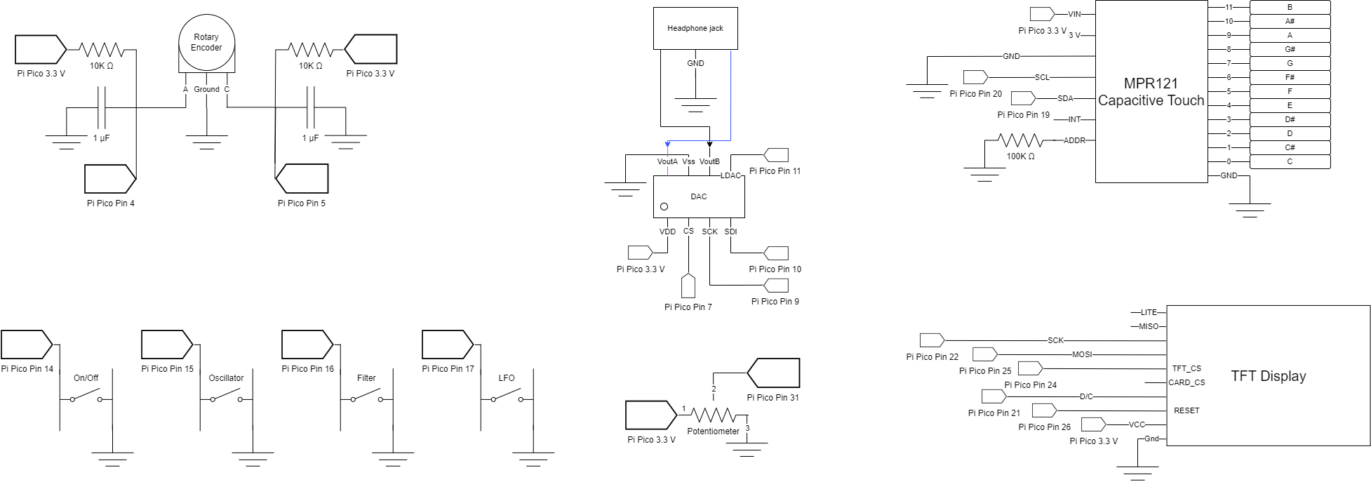
Wiring Diagram
A link to the pdf version of this wiring diagram can be found here.
Hardware Interfacing
The Hardware interfacing started with using the VGA to display the text for the oscillator, filter, and low frequency oscillator menus. We then moved the display to the TFT to have everything on one board and make it more portable. The text display consisted of three parts: the text for each menu, the values for each variable, and the indicator for what variable is currently being selected. The TFT display also had its setup initialized similarly to the VGA and placed in its own function, initialize TFT.
The text for each menu was stored in an 2d array and iterated through using a for loop to avoid hardcoding the places where the text would be. This was a similar process for displaying the values for each menu. The values were stored in a 2d, fix15 array and were printed out so that they were next to the text label.
The menu text was updated only when a different menu was selected to avoid refreshing the TFT display unnecessarily. The values in each menu were only modified if they were updated by the hardware polling and the selector was only changed if the rotary encoder interrupt was turned enough to change the selector’s position.
The TFT display updates and polling for the inputs were based on interrupt timers, so making sure that the interrupts were as short as possible was very important, so reducing unnecessary updates helped speed up other parts of the system, like the capacitive touch interrupt.
We had to add some extra variables to the menu, but this only required adding the variable name to the respective menu text list, extending the storage array for that menu’s variables, and incrementing the size of the variables in that menu, making it very easy to add and remove variables as needed and allowing for new menus or variables to be added if desired.
We had four buttons, 1 rotary encoder, 1 potentiometer slider, and 1 capacitive touch breakout board - and these all needed to be polled and processed by the Pi Pico.
First, these inputs were all set up using a single function to avoid duplication functionality by iterating through a list of pins that needed to be set. The rotary encoder and potentiometer had their own functions and were also set up as well. The ADC was also set up and selected input 0 corresponding to pin 26 where the potentiometer was connected.
The inputs all had their own getters that made it easy to quickly poll a button. Buttons used getButton with the defined name of the button being passed to an array of buttons to easily select the correct pin without needing to know the number and use this key elsewhere when selecting different menus. The rotary encoder had an interrupt that called updateRotaryCounter that checked if rotary encoder pin A was low, and incremented or decremented a tiny counter if the rotary encoder pin b was high or low respectively. This tiny counter would increment or decrement the rotary counter after hitting its max or min to avoid having accidental selection changed if the rotary encoder was bumped and moved. The logic for the rotary encoder was from Haris’s blog that can be found here
The potentiometer used the ADC in the Pi Pico on GPIO pin 26 to get its value and convert its value to a fix15 to be used by FFT and audio synthesis.
The potentiometer would only modify a value if the last value set and the new value of the potentiometer differed by .05 to avoid setting values by accident when rotating though the different variables with the potentiometer. This also tied in to the TFT interrupt being able to reduce refresh rates for the display.
With all the inputs set up, an interrupt timer was created that would call our function to check the status of all the inputs.
We used a function called getNewHardwareValues to check and poll all inputs to see if the TFT display or variables should be changed.
The first thing checked was if the yellow toggle button was pressed. This button would turn the respective menu’s functionality on and off and was used by the audio synthesis when seeing what should be applied to a waveform.
Next, the three buttons corresponding to the oscillator, filter, and low frequency oscillator were checked. If the button corresponded to the menu currently shown, nothing would be changed, otherwise, the two flags, groupSettingUpdated and numbersUpdated, were set to true so that the TFT display update functions would run. The rotary encoder would also be set to 0 to make sure the first variable is selected in that menu.
The current variable selection is then checked by taking the mod of the current rotary counter value and the number of variables the menu has, with a 1 added to skip over the on/off variable that is only set by the yellow button. Following this, the potentiometer value is polled only if it has been moved more than 5% of its length if a new variable or menu has been selected, otherwise the value is polled as normal and the numbersUpdated flag is set to true to update the numbers.
Wherever a value is set, the current menu and variable is passed to a general function that checks which setter should be used based on the menu being shown and uses its respective setter. Inside this setter, the variable is scaled if needed since the potentiometer returns values from 0 to 1 to simplify scaling. For the type and shape variables that had multiple settings they were selected based on the range of values, like 0 to .25 referring to a different value that from .25 to .5. This made it easy to use the potentiometer for all values, excluding the on/off setting for each menu.
The capacitive touch sensor was separately built and tested from the rest of the input hardware.
Difficulties
Interrupt + Protothread Conflicts
Due to the strict timing requirements for DDS, it was done via an interrupt that used a repeating timer callback as its signal. This interrupt was called at 20 KHz, which resulted in us not being able to run protothreads for other functions. Instead, we put those into interrupts of their own which seemed to work well.
Filter Calculation Speed
Originally our LFO was doing calculations in the same interrupt as the DDS output. This caused a large amount of lag to the point where the calculations slowed the resulting output wave and we could hear the, for example, curve of a sine wave rather than a high-frequency tone.
This was resolved by moving the LFO into a different interrupt and using a buffer wavetable to allow for the DDS output to switch seamlessly between different filtered wavetables.
LFO Smoothness
One of the results of moving the LFO to a different interrupt is that the transitions between filtered waveforms is not as smooth as we would have liked. This is more noticeable with lower frequencies as it becomes easier to detect a step change in the sound.
Sampling Rate
The original sampling rate in the base code that we worked with was 40 Khz. We lowered it by half to accommodate for all the calculations and input detecting we were doing.
Capacitive Touch Sensitivity
The demo code we built our capacitive touch functions off of was too sensitive for our uses, where it would register a release even when a key was being held down. We pinpointed the issue to the filtered sensor value decreasing over time until it became close to the baseline value, in which case the code detected it as a “release”. This was fixed by tuning the touch and release thresholds by setting the release higher than the touch threshold, bypassing the check entirely. To account for small changes in touch, we added a buffer that would only signal a release when a sequence of releases were sensed rather than signal as soon as a release is detected. This helped for a more consistent user experience when using the touch keys.