Introduction
Final Project Demo Video
Description
Project Breakdown
Summary
Approach
Modularity
Our project can be split into two main categories: sound design and user interface.
The sound design aspect of the project was almost entirely software.
User interface was a combination of hardware and a programming a display.
Merging sound design and user interface required various sound design parameters to be linked hardware-triggers.
Encapsulation
Most functions / modules were tested separately and contained in their own initialization and usage functions. Even with a large file, code was clearly sectioned based on use.
Steps
The first task of this project was to modify the sinusoidal oscillator from a previous lab to play a pure tone. Rather than synthesizing cricket chirps at a pure tone with a set envelope, we disabled all features in order to have a constant wave output. This would allow us to debug using an oscilloscope for the next steps of the project.
Our next main task was to implement frequency filtering. There are three types of frequency filters in this project: low-pass filtering, high-pass filtering, and band-pass filtering.
Instead of outputting an audio signal and then filtering it through a circuit, we filtered the signal via software before outputting it. This allowed us to save space on the breadboard and keep more of the synthesis portion of the project in the code.
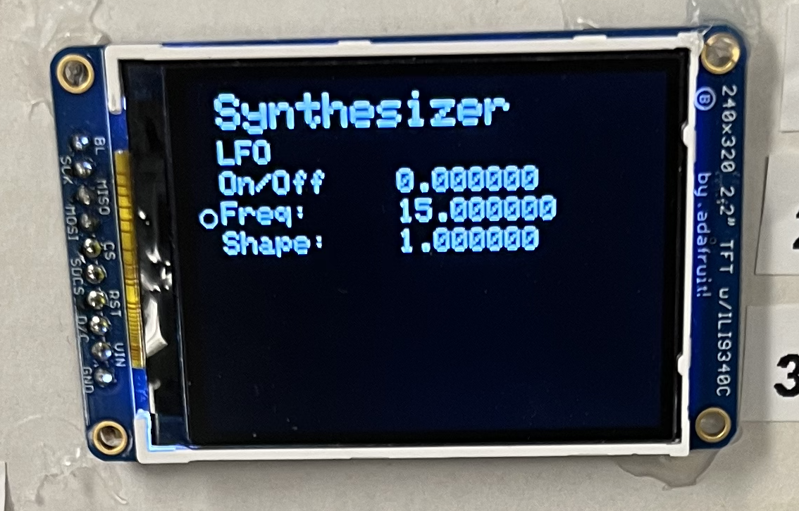
Alongside the software development, the hardware was also set up. We created three menus for the oscillator, filter, and low frequency oscillator and had them display on a small TFT display. We made it so all the variables for these menus would be populated using a modular loop instead of hardcoding their places to make it easier to add or remove variables - or more menus - in the future. We also created two mini-testing demos for the potentiometer and the rotary encoder before tying it together with the FFT and audio synthesis functions.
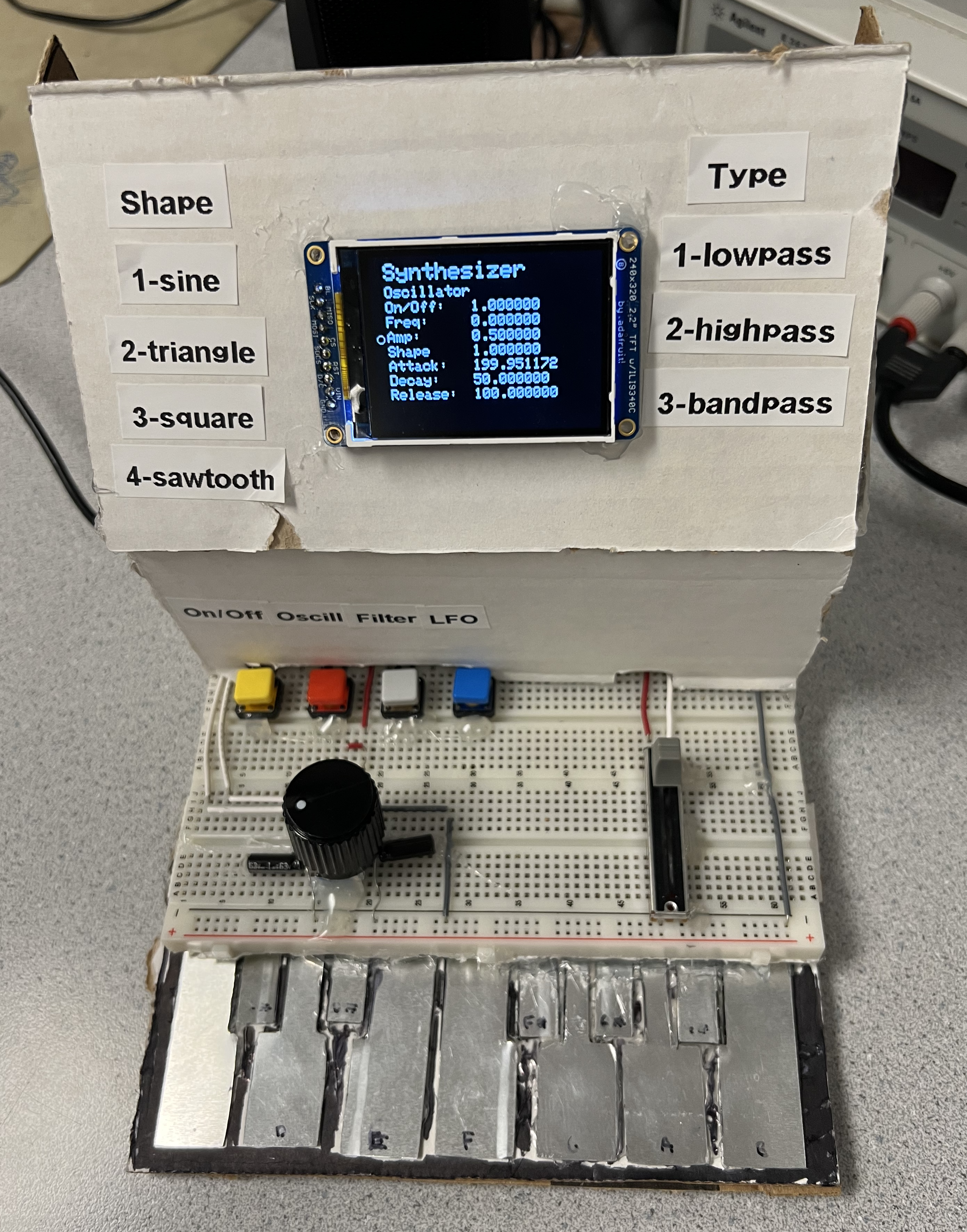
We also created a mockup of the user hardware interface using foam to place buttons and sliders before adding them to a breadboard and gluing them and cardboard covers together to hide and protect the wiring, as well as create a compact and portable frame for the synthesizer.
Gallery
Front View
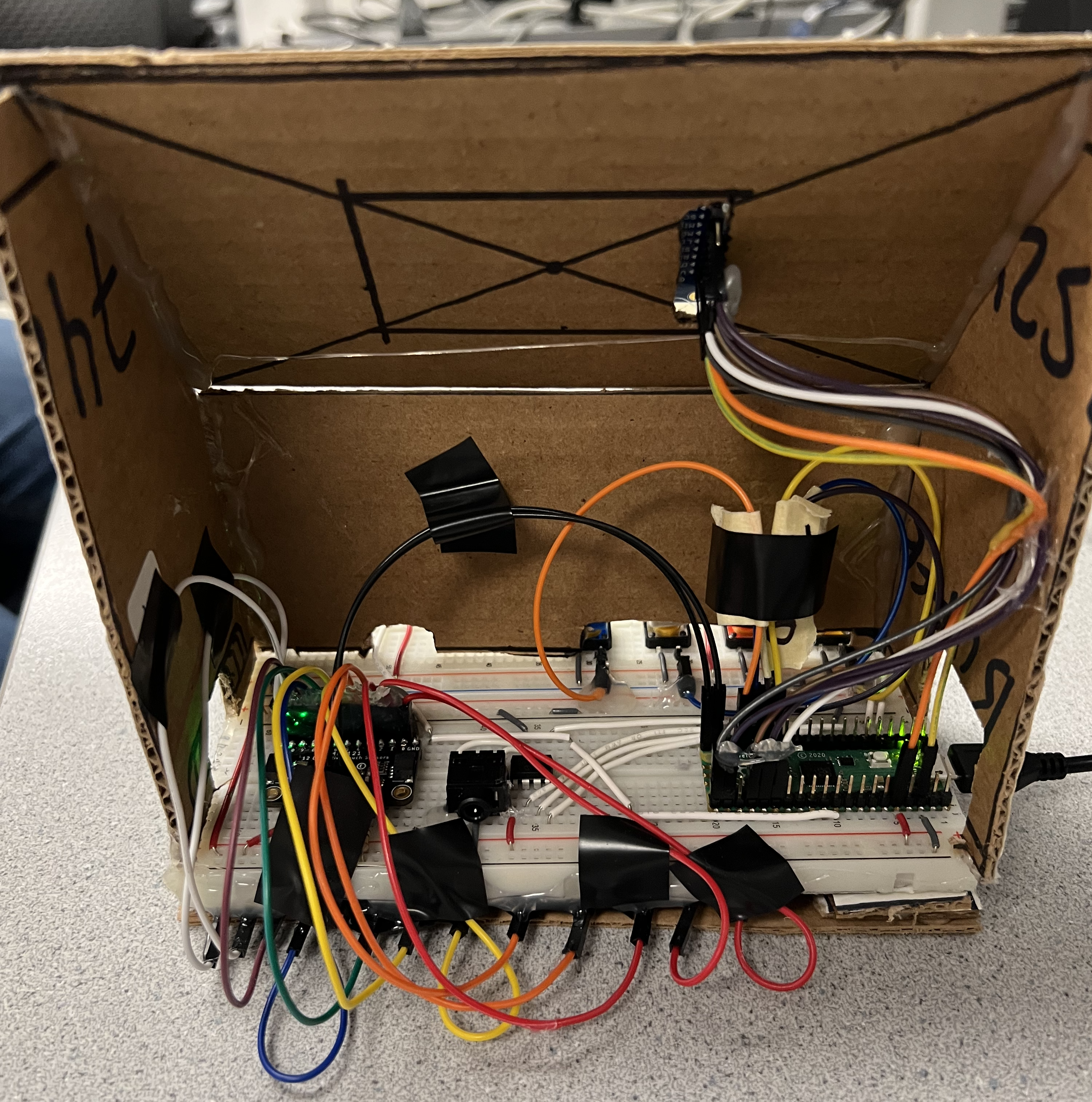
Back View
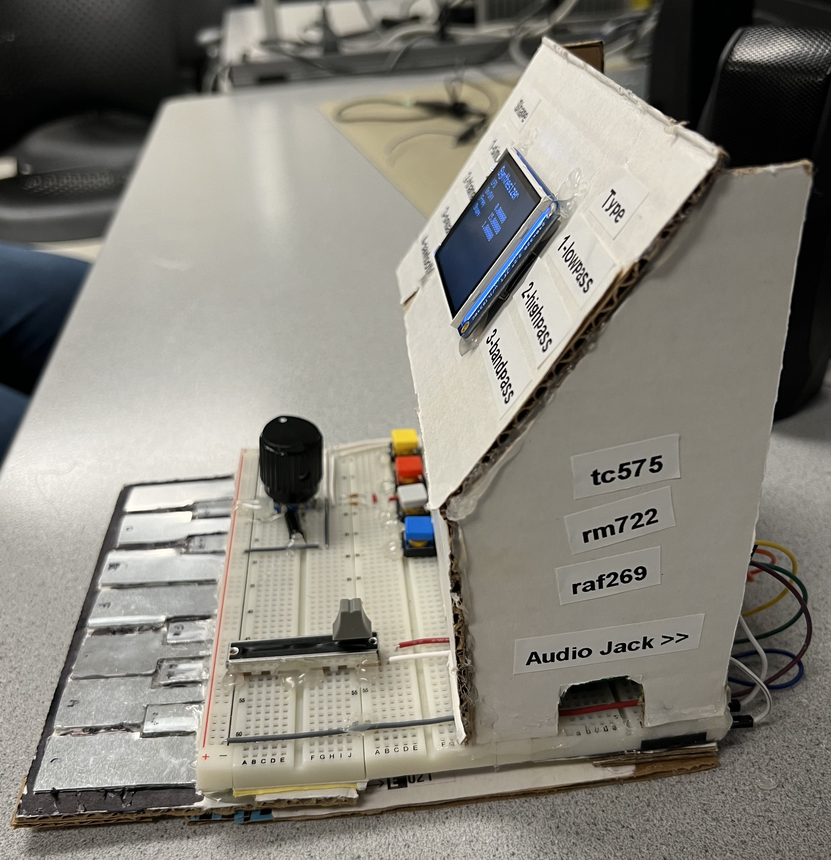
Side View
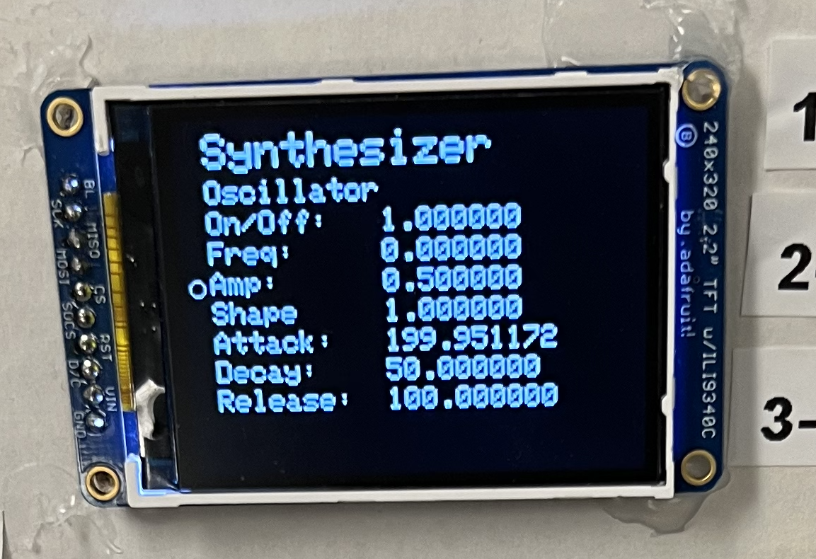
Oscillator Menu
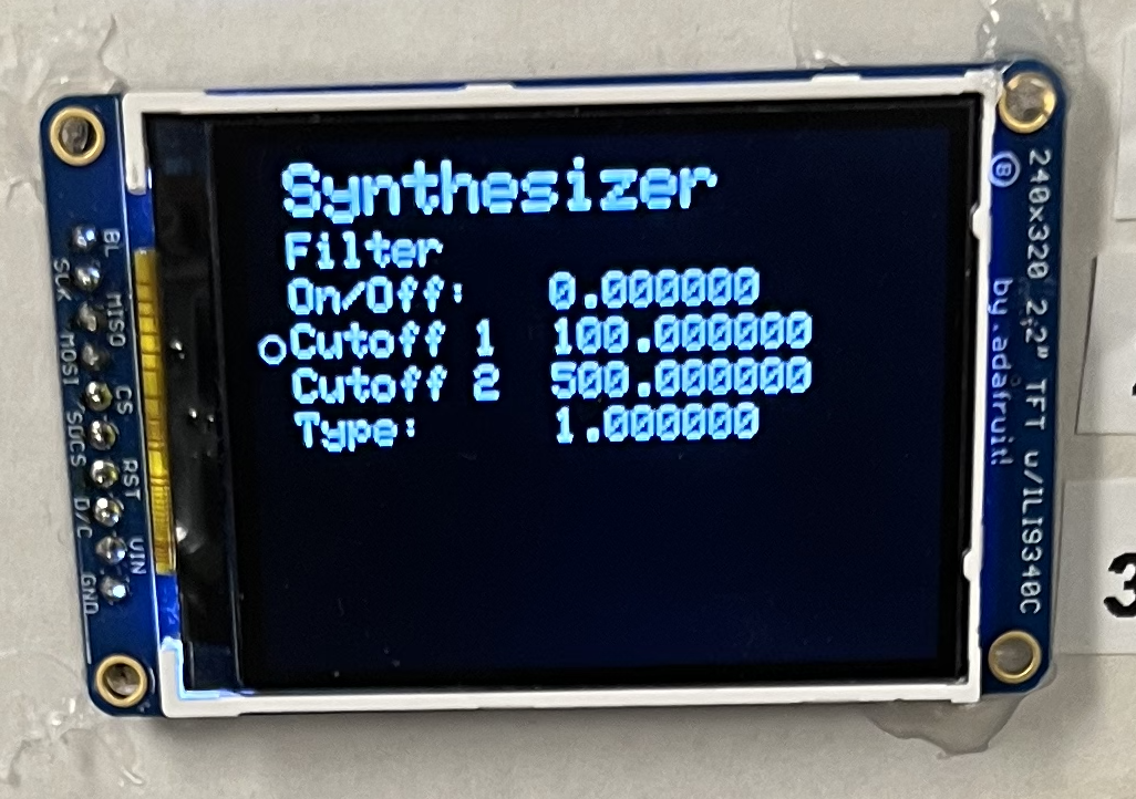
Filter Menu
LFO Menu