Introduction
“Linus” is a 2D-drawing machine which uses a marker to draw inputted images in the one-line-drawing art
style!
Created by Sidharth Rao, Kelvin Resch, and Rachel Arena. Our GitHub Repo is here.
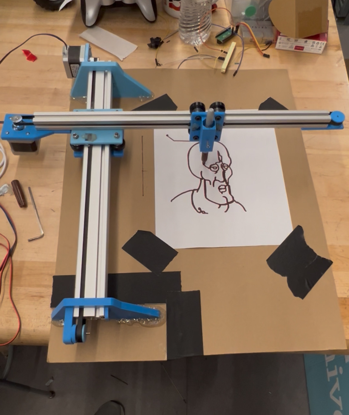
In this project, we designed and built the Line Illustration for Natural, Uninterrupted Sketching
machine (LINUS),a 2D-drawing machine that replicates input images in a one-line-drawing art style using
a marker on paper. The system integrates image processing, optimal path planning, and precise motor
control to produce clean and efficient renditions of complex images. Our work centered around three key
components: a slicer to process and optimize the image, a Raspberry Pi and Pi Pico pair for
communication and control, and a custom-built XY plotter driven by stepper motors.
The Raspberry Pi serves as the main controller, taking a user-supplied image and running it through our
custom slicer algorithm. The slicer reduces the image to essential features and then computes an
optimized continuous path that minimizes extraneous marker movement while maintaining visual fidelity.
This path is then streamed via UART to the Pi Pico, which manages stepper motor control. The Pico drives
the drawing head along the computed trajectory, sending “READY” signals back to the Pi after each
segment is completed, ensuring synchronized and controlled motion.
Building LINUS required a combination of software and hardware design, from implementing optimal routing
algorithms and controlling stepper motors to assembling a custom mechanical frame. This project
reinforced key concepts in embedded systems, computer vision, graph algorithms, and real-time
communication. It also demonstrated how physical constraints shaped our algorithm design, giving us
hands-on experience with the challenges of translating digital instructions into real mechanical motion.
Inspiration
Our project idea came from seeing Hunter Adams’ example of using DDS to control an etch-and-sketch combined with his demonstration of using the Fourier Series to recreate Picasso’s one-line-drawings. We thought it would be interesting to automate the entire process of creating one-line-drawings physically, from an input image to the output image drawn by a marker.
High Level Design
General Process
Our project had three major parts:
- Slicer: Image processing and optimal marker routing
- Electrical Hardware: Communication and Stepper driver control
- Mechanical Hardware: Mechanical assembly and 3D-printed parts
A Raspberry Pi acts as the main controller. We give an image as input, and our slicer then processes the image to extract a minimal amount of important features and borders. The slicer then finds the best way to route the marker in one line over the processed image. It aims to minimize the amount the marker draws in an image, and especially the amount of space the marker draws on the paper that is not in the processed image.
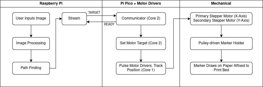
The Raspberry Pi takes the path outputted by the slicer and turns it into a UART stream, sent to the Pi Pico coordinate by coordinate. The Pico drives the stepper motors (one for each axis) at constant velocity towards the current target coordinate. When it reaches the coordinate, it sends the Raspberry Pi a “READY” signal, indicating that it is ready for the next coordinate in the sliced path. The stepper motors drive a marker holder, which draws with the marker on a piece of paper attached to the print bed.
Overall System/Process Diagram
Results
The LINUS drawing machine performed very reliably. Once a drawing command was issued, the CoreXY
mechanism executed paths with minimal hesitation, and the stepper motors moved smoothly without
noticeable flicker or stutter. During testing, the system could complete a typical sketch in 1-2
minutes, depending on the complexity of the input and density of control points. Movement speed was
capped to avoid mechanical failures, but path execution remained responsive and fluid throughout.
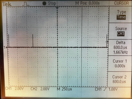
We verified the performance of our stepper motor signals using an oscilloscope. As shown in the left
figure below,
the step pulses had a consistent spacing of 600 us, corresponding to a step frequency of 1.667 kHz - a
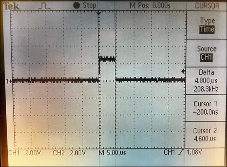
rate we used during normal drawing operation to balance speed and mechanical stability. Additionally,
the pulse width, as shown in figure below to the right, was measured to be 5 us, which is well within
the required range
for reliable triggering on standard stepper drivers. This also matches the intended behavior in the
Pico’s firmware. These measurements confirm that our firmware generates clean, consistent pulses that
are both frequent enough for smooth motion and long enough to be correctly interpreted by the driver
hardware. Together, they validate the system’s ability to produce stable and accurate motion critical to
LINUS’s operation.
The system achieved a drawing accuracy of approximately +/- 3mm, which was more than sufficient for
producing clear and recognizable sketches. Minor inaccuracies were primarily caused by belt tension
variations and the occasional slipping of the marker, which sometimes introduced slight wobbles in the
drawn lines. However, these issues were largely resolved by properly tightening the related bolts. When
the system was set up correctly, it operated without noticeable accuracy problems.
We can quantify this accuracy by examining the final drawings, specifically in regions where the plotter
retraced lines. In these cases, the lines became slightly thicker but showed no visible gaps, indicating
that the repeatability was within the width of the marker tip (3 mm). This small overlap not only
validated the system’s precision but also produced an unintended aesthetic benefit, creating a shading
effect that enhanced the visual appeal of the output.
In terms of image processing accuracy, edge detection consistently identified major contours in test
images. While finer details were sometimes lost in thresholding or during resolution downsampling, the
general structure of each image was very well preserved. The entire purpose of LINUS was to take images
and convert them iconized drawings, so we finely tuned our image processing algorithms to discard a
certain level of detail that would make the output consistent with an icon.
The conversion from pixel space to drawing coordinates introduced only minor distortion, with the final
outputs definitely reflecting the input images’ shape and proportions. Since we settled on a system that
could only drive the motors at -speed, 0, and +speed, the pen can only move in cardinal and ordinal
directions. This is not an issue, however, because our generated waypoints are very close together, so
we are still able to draw curves smoothly. If our waypoints were not so close, an issue would arise
where curves would become corrugated, but this can be solved by interpolating between points and
increasing waypoint density.
To enforce safety, we implemented several design decisions. Power came from a current-limited power
supply, and all wires were routed securely so as to avoid entanglement with moving parts. Motor speed
was capped to avoid disastrous and potentially dangerous mechanical failures, and soft stops were
implemented in software to prevent the motors from exceeding the physical bounds of the drawing area,
reducing the risk of mechanical damage.
LINUS was designed for ease of use by both team members and untrained users. Users can load an image and
start the drawing with a simple command, watching as the system renders the sketch automatically on
paper. Overall, we were very happy with the results, and genuinely enjoyed seeing our input images come
to life in the one-line drawing style!
Conclusions
This project successfully demonstrated the design and implementation of LINUS - an
Etch-A-Sketch-inspired automatic drawing machine. Our system used a CoreXY style belt drive mechanism to
control the movement of a marker, allowing us to translate digital images into continuous, drawable
paths using edge detection and graph algorithms. The mechanical structure achieved
consistent movement with excellent stability and accuracy. On the software side, the system achieved
accurate feature simplification and optimal path planning with one-line-drawing constraints. While the
final
drawing fidelity was slightly limited by the resolution
and mechanical accuracy of the system, the curves traced on paper generally reflected the structure of
the original image.
In the future we could improve the smoothness of the mechanical design by using V-slot rails instead of
T-slot rails. In the slicer, we could also transform our slicing problem into existing solved problems
like the Chinese Postman Problem, making our process even more efficient. Electrically, transitioning
from a protoboard to a custom PCB would streamline the overall system design by integrating all the
components into a compact and permanent layout. This would improve durability, reduce wiring complexity,
and be easier to replicate.
Not only did we successfully meet our goals and expectations laid out in our project proposal, but we
followed engineering best practices throughout the design and build process. This involved modularizing
our code for readability, reusability, and ease of configuration, implementing thorough hardware testing
before system integration, managing power distribution safely, and maintaining clear documentation for
both hardware and software components.
We took inspiration for the mechanical design from existing 3D printers and this youtube video,
but we made our own custom components and there were no patent issues. We used the following libraries:
NumPy, OpenCV, Pillow, PyGame, Scikit-Image, Scikit-Learn, SciPy.
This project gave us the opportunity to merge artistic and engineering disciplines in a uniquely
rewarding way. We applied concepts from microcontrollers, control systems, image processing, and
mechanical design to build a system that could physically render an artistic interpretation of digital
images. LINUS not only fulfilled our original vision but also reinforced many of the core topics we
explored throughout the semester, providing a hands-on synthesis of theory and creativity.
Appendix A - Project Display Inclusion
The group approves this report for inclusion on the course website.
The group approves the video for inclusion on the course youtube channel.
Appendix B - Repo (Code, CAD)
Repo LinkAppendix C - Datasheets
Stepper Motor DriverStepper Motors