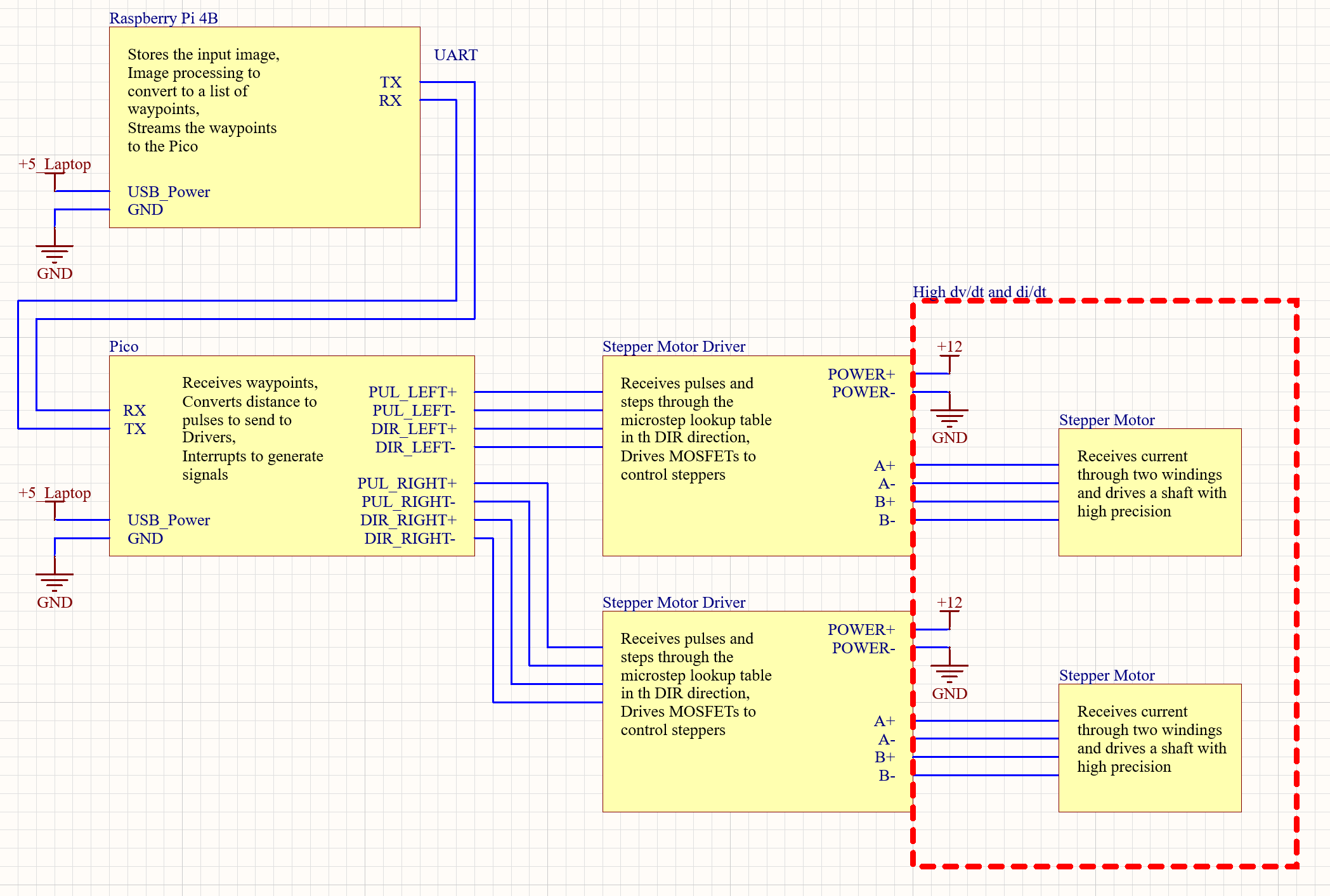
System Overview
Electrically, the system was comprised of six parts:
- 1 Raspberry Pi
- 1 Pico
- 2 Stepper Motor Drivers
- 2 Stepper Motor
Information travels mostly in one direction, from the Pi to the motors, except for the duplex line between the Pico and Pi. We designed our system to minimize interconnectivity in order to make debugging and integration easier. For example, we chose stepper motors because they could do open-loop position control very precisely.
System Diagram
Detailed Technical Description
Raspberry Pi
LINUS starts at the Pi. Here, the input image is stored and input into the slicer. The slicer takes the image and processes it to create a list of waypoints stored as pixel values on a 480x480 grid. Details about how the Pi turns a general image file into this list can be found in Slicer page.
This list of waypoints represents a list of position setpoints for the stepper motors to get to. The waypoints are densely populated along the planned path so that there is a small distance between each waypoint. This small level of subdivision allows us to paint smooth curves with the stepper motors.
UART Communication
Now that the Pi has the list of waypoints to send to the Pico, it opens up a serial communication connection with the pico. UART is a full-duplex communication protocol that uses a TX, RX, and GND line to send bits between two devices. UART doesn't use a controller-peripheral architecture, unlike other common communication protocols such as I2C, SPI, and CAN. The Pi and Pico can communicate with each other independently. In our system, we sent strings over UART and parsed them on the receiving end.
Once the UART line is up, we poll the RX line on the Pi to see if the Pico has sent a “READY” string, signaling that it is capable of receiving and executing a waypoint. If so, the Pi will send a waypoint “(X, Y)” over to the Pico. It will then continue polling the line until either the Pico sends “READY” again or the Serial object disconnects.
For debugging purposes, the Pi can also generate an animation of how the Pico would draw the list of waypoints through a pygame window.
Pico
The Pico is responsible for receiving waypoints from the Pi and outputting PUL and DIR signals to the two stepper motor drivers to move the motors. In this project, we decided to use stepper motors and open-loop control for simplicity in design.
The pico stores two stepper motor structs that store information about configuration (max velocity, GPIO pins) and current state (current position, target position, current velocity).
Core 1
This core is responsible for communication with the Pi. We needed to use both cores because we have interrupts that generate pulses to the stepper motor driver, and each pulse is generated by one interrupt call. Since our high-precision application required microstepping, we would send thousands of pulses per second to the stepper motor drivers, which would be interrupted by UART writes and reads.
The core begins by initializing the UART peripheral and the motor target positions. Each motor controls movement along one axis, so one motor gets one setpoint along the x-axis, and the other motor gets a setpoint along y.
Then, the core enters its main loop, where it will continuously poll both motors' current and target positions. When one motor reaches its target position, the core will write “READY” to the UART line, signaling to the Pi that the Pico wants to receive a waypoint. It will then read from its UART RX line for the waypoint “(X, Y)” and store those values into the targeted positions for the X motor and Y motor.
It will then go back to checking if the motors have reached their target positions and continue the loop.
Core 0
Core 0 is responsible for interfacing with the stepper motor drivers. In this dual-core architecture, each variable is only written by one core, so there are zero risks of race conditions. We designed the motor structs this way so that we wouldn't have to worry about multithreading debugging, and so that the behavior of one core is completely decoupled from the behavior of the other.
After initializing GPIO and core 1, core 0 jumps into its main loop. Here, the Pico will check if the current position matches the target position for each motor. If not, it will set the DIR pin to its required state, and bring the PUL pin high. If the current position matches the target position, it won’t set the PUL pin high.
After setting the DIR and PUL pins of both motor drivers to their proper states, core 0 will sleep for 5 microseconds. This is the pulse width. The stepper motor drivers use pulse frequency modulation, and this will be covered in depth in the “Stepper Motor Drivers and Stepper Motors” section coming up.
After sleeping for the pulse width, core 0 will check if the PUL pins are high, and if they are, it will set them low and increment the current position of that motor. It will then sleep for 1200 microseconds, which is the distance between the pulses. This means our pulse frequency is actually fixed, so we only drive the stepper motors at 0, - max_velocity, or +max_velocity.
The Beauty + Importance of System Simplicity
While it might seem crude to make a system that only drives at three speeds, this was the simplest option out of the many that we successfully implemented. We originally had a system that would generate pulses using interrupts. Each interrupt call would set its own hardware alarm timer to a specific value depending on the desired motor speed (proportional to pulse frequency). This would allow us to drive both motors at different speeds, and we could precisely control the speed.
We also implemented acceleration clamps, which would prevent the motor from accelerating too quickly and slow down the motor as it approached a waypoint. We did this because we wanted a smooth motion through waypoints, and we were concerned that the momentum of the rails would cause the stepper motors to stall when accelerating.
As we tested the system, we raised the acceleration clamps higher and higher until they were functionally not doing anything. Even if the motors instantaneously went from 0 to maximum speed, they still didn't stall, so we removed the code.
Since the motors didn't need the acceleration clamps, they only needed to be able to drive at three speeds. We thus removed those features and the interrupts as well, and rewrote the software in a simpler fashion to improve long-term maintainability and readability, especially since this code may be public for others to read after our project is published.
Stepper Motor Drivers and Stepper Motors
The Stepper Motor Drivers receive data signals to move from the Pico, and output power signals to the motors to move them. The driver needs two pins to do this: PUL and DIR. DIR will tell the driver which way to turn the motor, and PUL will tell the driver to step once in the DIR direction. We can decide the microstepping resolution of the driver and set it to any multiple of two between 1 and 32. Stepper motors have 100 magnetic poles or 50 pole-pairs on the rotor. They also have two independent windings in the stator that control the rotor.
If you can only drive each winding off, full in one direction, and full in the other direction (with an H-bridge), then you are full-stepping. The full-stepping resolution of a stepper motor is 200 steps per revolution. By microstepping, you drive one winding at less-than-full voltage by PWM-ing on the H-bridge.
The stepper motor driver is able to do a microstepping resolution of 32, which allows us to do 200 * 32 = 6400 pulses per revolution. Internally, the stepper motor driver does this by storing an array 6400 elements long called the microstep lookup table. Each time a falling edge is detected on the PUL input line, the driver increments through the lookup table some amount. If the microstepping resolution is 32, then the driver will increment one position through the array. If the microstepping resolution is 1, then the drive will increment 32 positions through the array. The array contains the PWM duty cycle of the A and B windings. This value gets scaled by the motor drive strength, and then that value is directly sent to the PWM module and gate drivers of the MOSFETs. The DIR pin decides which direction the driver should step through its lookup table.
Changing the PWM duty cycles of the A and B windings of the motor will change the amount of current traveling through them. This modulates the direction of the magnetic field that the rotor sees, and if the rotor’s own permanent magnet field is not aligned with the stator windings' field, then a torque will be applied to the shaft to move it to where the windings want the rotor to be.
Each time the PUL pin is pulsed, the stators magnetic field changes by some position. If the PUL pin is not pulsed, the winding currents will not change, and the rotor will remain in its place. By sending pulses at a specific frequency, the magnetic field position will change at a specific rate. This means that if we control the driver using PFM, then the PFM is modulating the motor's speed, which is very different from other motor applications, where the current is modulating the motor's torque. This unique feature of stepper motors allows us do open-loop position control with very high precision. 6400 pulses per revolution means we can move LINUS's pen with a precision of <0.001 inches.