
Design
Program Design
The program is organized such that there are two protothreads and an ISR handler. The first protothread takes care of updating the motor state and current song being played with two different button FSMs. The second protothread updates the neopixel strip according to the current song being played. The ISR handler (alarm_irq) is in charge of actually playing the song using DDS.
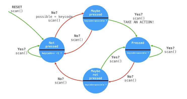
The input protothread, constantly loops using a while statement to continuously poll the GPIO pins that the motor button and song button are connected to as well as update the ultrasonic sensor to detect the distance an object is from the sensor. To measure the distance between the ultrasonic sensor and an obstructing object the measure_distance() function is called. This function sends a trigger pulse wave and then measures the time between the time this trigger pulse is high and the echo pin goes high. By using the time for the trigger pulse to reflect back to the sensor to calculate a distance measurement. Due to this value being quite noisy and variable during testing the value was low-passed in software to obtain a stable value is returned. If the distance returned is less than 60 and greater than 0, indicating that there is an object nearby, the current song will be toggled to Brahm's lullaby by setting music equal to 1 and resetting the DDS parameters. Afterwards, the current values of the GPIO pins associated with the motor button and the song button are collected using gpio_get(). Following this, there are two different button debouncing FSM's: one for toggling the current state of the motor either on or off, and one for toggling the current song being synthesized.
The button debouncing FSM essentially detects a valid button press, and then saves its value as a previous parameter. If the machine detects that a button press is the same after reading the value of the GPIO, the machine determines that the button is pressed and an action is taken. While the current value is still equal to the previous value, the FSM will remain pressed until the current value is no longer equal to the previous value. When the current value is no longer equal to the previous value for two consecutive cycles, then the FSM returns back to the not pressed state. In the case of the motor button FSM, the current state of the ‘butt_pressed' flag is toggled. If ‘butt_pressed' is high, then the current motor direction is toggled and the motor is turned on by setting the motor speed to be 125000. If ‘butt_pressed' is low, then the motor speed is set to 0 to stop the motor from spinning. For the song FSM, if the button is pressed ‘music', which is used to determine the current song being played, is incremented by 1 (or if the current value is 3 then it will be reset back to 0). After toggling music, all of the DDS parameters are reset back to 0 and the alarm interrupt is scheduled. Within the ISR handler for the songs, a counter is incremented to keep track of how long the note has been playing.
Each time the ISR handler is entered, a fixed increment of DDS_increment (which is scaled by the full range of the phase accumulator divided by the sampling frequency 50kHz), which represents the frequency of the desired sound to be played, is added to the phase accumulator. The phase accumulator is then shifted to obtain the top 8 bits (don't need a 232 entry sine table), which is then used to look up the amplitude of the sine wave. This process repeats until the current count reaches the total number of audio samples required to generate the desired sound.
A protothread named protothread_led was created to swap the color sequence displayed on the neopixel LEDs. There are four different color sequences that are displayed using the neopixel LEDs: static white when no song is playing, pulsing colors for each new note played during Brahms' lullaby, random twinkling lights throughout Twinkle Twinkle Little Star, and a blue color-chasing effect for Baby Shark.
To display colors on the neopixels, two different helper functions were created: urgb_32 which converts RGB values into a 32-bit integer in GRB value and put_pixel which sends a 24-bit GRB color to the PIO state machine that controls the neopixels. The urgb_32 function takes in an input of 3 different 8-bit integers, each integer representing the intensity of red, green, and blue. The function takes the input values, shifts the green value left by 16 bits and red bits left by 8 bits, and then ORs these values with the 8 blue bits. This essentially creates a 32-bit GRB value, in which the intensities of green, red, and blue are located on the lower 24 bits. The put_pixel function takes in a 32-bit GRB value and shifts it by 8 bits left since only 24 bits of GRB values are needed. Then, the value is sent to the PIO machine by using pio_sm_put_blocking to display the color on the neopixel LEDs.
Inside protothread_led, a series of if statements are used within protothread_led to determine which color sequence to display based on the current value of ‘music', which indicates which song is playing. Inside of the alarm_irq (interrupt handler discussed more below), an array base_color is updated to contain one of 7 different RGB values for pastel colors from the colors array. The colors array contains 7 different sub-arrays of RGB values for different pastel colors. The base_color array is only updated after a note is determined to be completed playing.
If no song is playing (music = 0), a for loop that loops through all of the LEDs uses the put_pixel function to send the GRB value of 0xFFFFFF to the LEDs which is a static white color.
If Brahm's lullaby is playing (music = 1), a for loop that loops through all of the LEDs uses the put_pixel function to send the GRB value located in the base_color array. This creates an effect where a pastel color will be shown for the duration of a note, then will change color upon the playing of the next note.
If Twinkle Twinkle Little Star is playing (music = 2), a twinkle effect is shown on the LEDs by creating a 15 percent change of displaying the base color on the LED. Upon each iteration of a for loop going through all of the LEDs, a random number from 0 to 100 is generated, and if the number is less than 15 then a color is displayed. In other words, there is a 15% chance that any given LED in the strip will illuminate. Additionally, the color that the LED will be is determined by randomly generating a random number from 0 to 6, then accessing the RGB value corresponding to that index from the colors array. Then, the put_pixel function displays this value after converting it into a 32-bit GRB value using the ugrb_u32 function. If the random number generated is not less than 15, then a value of 0 is sent to the neopixels using put_pixel, which turns off the LED.
If Baby Shark is playing (music = 3), then a color-chasing effect is displayed by essentially creating a gradient. On each iteration of a for loop going through all of the LEDs, an intensity value is calculated by taking the index of the LED and offsetting it by water_offset. water_offset is a constant value that shifts the gradient forward by 40 LEDs upon the completion of the for loop. After calculating the intensity, the blue level to be displayed is calculated by multiplying 205 by the intensity divided by the total number of LEDs and adding 20, essentially creating a range of blue shades from 20 to 225. Afterwards, this blue value is put onto the neopixel LEDs by using put_pixel of a urgb_u32 value.
In addition to the two protothreads, there is also an alarm_irq interrupt handler used for the music playback. When the program enters the ISR handler, the program clears the interrupt flag then schedules the next interrupt. Afterward, it checks the current state of ‘music' to determine what action to take. If ‘music' is non-zero, a song will be played. All of the songs are stored in fixed arrays storing the different frequencies and notes durations in memory, and then synthesized whenever the program enters the ISR handler. When the program enters the ISR handler to play a song, two counters are used to keep track of the current note being played within the song (note_count) and to keep track of how long a note has been playing (count_0). To play a note, the phase accumulator is set to be the frequency value of the current note desired to be played (stored in memory) multiplied by 232/50000. This value is then looked up in a sine table and the amplitude was modulated using amplitude modulation as described previously before being sent to the DAC to be played. This process is repeated until count_0 reaches the duration that the note should be played for (stored within memory). After the note is finished playing, another counter is started to not play any note when entering the ISR handler to create a short pause in between the notes, then the note counter is incremented by one to continue playing the song.
For Brahm's Lullaby and Baby Shark, the full songs and note durations are stored in memory. However, for Twinkle Twinkle Little Star, the song has a very repetitive nature, allowing for some optimizations to reduce the amount of memory needed to be allocated to store the song's note frequencies and durations to allow for additional songs to be stored in the future. Twinkle Twinkle has four sections of 7 notes, in which each of the 7 notes has the same note duration among the four sections, therefore it is possible to just store loop through the duration arry every 7 notes and change the frequencies based on what note needs to be played. To accomplish this an additional counter was used to determine which note in the sequence of 7 should be played, such that upon each entry into the ISR handler, a counter ‘twinkle_section' is updated every time one of the four sections of 7 notes is completed to advance the song.
With these protothreads and initializations of hardware in main() the full baby mobile system is functional. Some of the major challenges during this project included working with the neopixels and determining how to initially set them up since we had to determine how to get the neopixels to illuminate initially, but following using the PIO example from Raspberry Pi examples a PIO was able to be used in order to deal with the timings for proper functionality of the neopixels.
Hardware Design
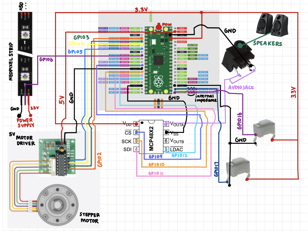
Our project consists of dual-channel DAC, a Neopixel strip, an ultrasonic sensor, a DC stepper motor, a motor driver, audio jack, two speakers, and buttons for external control of our system.
The DAC we used in our demonstration was a 12-bit Dual Voltage Output Digital-to-Analog Converter with an internal Vref and SPI interface. This device operated from a single 2.7V-5.5V supply that was compatible with our Pi Pico since our microcontroller could output a 3.3V power supply rail. The Digital to Analog Converter(DAC) takes snapshots of a digital signal and stitches them together to create an analog waveform. These snapshots are discrete increments, allowing “better” DACs to produce a higher quality of conversion and essentially a better sound. The DAC we chose to use produced sufficient sound quality to portray the specific audio chosen in the lab. Once we had confirmed the waveforms being generated by the DAC with the oscilloscope, we then integrated a 3.5 mm audio socket so that we could plug in speakers and listen to the generated “beep” sounds. This 3-prong audio jack requires no switch and can connect to two speakers in parallel.
The neopixels are individually addressable LEDs, where each LED can be set to its own color and brightness independently. All of the data needed are sent over a single digital line using I2C communication protocols. These LEDs are daisy chained, where LEDs are connected in series and data flows from the microcontroller to the first LED, then to the next and so on until the end of the LED strip. This strip operates typically at 5V, but we chose 3.3V logic, so that the brightness of the LEDs are dimmer, and thus less power consumption. Each LED expects a 24 bit color signal, where 8 bits each for Green, Red, and Blue are sent in order.
The ultrasonic sensor was chosen because we wanted to detect the baby’s motion while the baby mobile is at work. If the baby reached up towards the baby mobile, the ultrasonic sensor would then be able to detect and switch the current song to our most calming Brahms lullaby, in an attempt to calm and soothe the baby down. The ultrasonic sensor emits a high-frequency sound wave (40kHz) via a transmitter and waits while the wave travels through the air. Once this wave hits an object, in our case a baby’s hand, it will reflect back in the same direction it was transmitted towards the ultrasonic sensor. A receiver on the sensor detects the returning sound wave and the resulting waiting time between sending and receiving is used to calculate the distance of the object it had detected. The ultrasonic sensor we chose was the HC-SR04 model. This sensor uses 3.3V and has the transmitter and receiver as GPIO outputs, allowing us to collect real-time data of objects’ position using the microcontroller.
A DC stepper motor is a special type of electric motor designed to move in precise, discrete steps rather than rotating continuously. Unlike a traditional DC motor with brushes, it is a digitally-controlled motor that rotates in inputted fixed increments. These digital inputs are electrical pulses that the stepper motor converts into mechanical motion by moving a set number of degrees with each pulse and repeating these motions to rotate. The stepper motor we chose ran on 5V and is controlled by a motor driver. The motor driver is the middleman that translates low-power control signals into high-power signals that actually moves the motor, in the sense that the driver knows the correct timing and order for which coil is energized. They also control which coils get power and for how long, which helps generate smooth and accurate stepping. Our raspberry pi pico cannot supply enough current to drive the motor directly, thus the motor driver takes low voltage signals(on the range of 3.3V) and uses a separate power supply(on the range of 5v) and level shifts the output to the needed higher current and voltage which powers the motor coil. The motor driver also smoothly varies the current in each coil, resulting in smoother motion, quieter operation, and more precision. Even when the motor is stationary, the stepper motor applies full current to the coils, generating maximum holding torque. With these characteristics of high torque, smooth rotation, and low noise, we thought this kind of motor was best suited for our baby mobile, as we wanted something to be able to withstand heavy items dangling from the motor, and it must not scare the baby away.
The push buttons were additions that we added at the end to help control the different options our baby mobile could display. This included rotation direction of the motor and different songs and light patterns the neopixels and DAC can produce.
From the range of hardware items, we have two power ranges of 3.3V and 5V. This was ideal as the raspberry pi pico had two power rails both 3.3V and 5V, which was used by all of the hardware, except the neopixel strip for the reason mentioned above(large current withdrawal).
We originally had one common ground pin where we connected all of the grounds together to one singular ground GPIO pin. This resulted in a ringing in the speaker due to capacitive coupling with the ground signals between the stepper motor and the DAC. Thus, we separated the ground signals using different ground GPIO pins on the Raspberry Pi Pico which fixed our issue, as the ground wires had enough spacing between them to dilate the coupling enough to not be noticeable on the speakers.