Approach and Background
The first week of working on the project consisted of getting the stepper motor functional and 3D printing the mechanical arm setup. The stepper motor driver uses three different PIO state machines loaded onto PIO blocks in addition to DMA channels to control the stepper motor without detracting time from the cores to do other tasks or compute. These 3 different PIO state machines include the step counter machine, the pulse length state machine, and the pulse generating state machine[1].
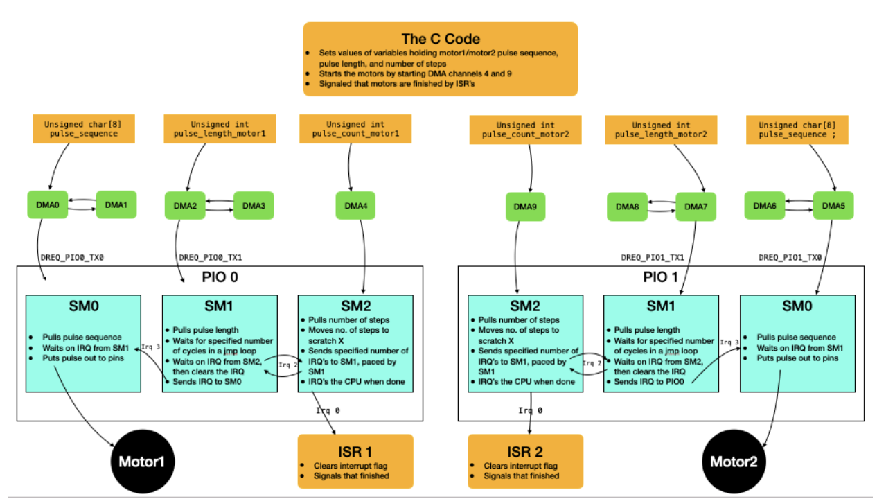
The step counter machine counts how many steps the motor completes and then signals the CPU once the motor completes the preprogrammed number of steps. To perform this action a 32-bit step count (up to 232 steps, ~2 days) is pulled from the FIFO into the output shift register and then moved to the X register to act as the count value and X will continue to decrement and signal to the pulse length state machine until X equals 0 and signals an interrupt to the CPU to clear the interrupt and then repeat the process. Note that this FIFO is filled by a DMA channel which is triggered in software to allow users to be able to start the motors at a specific time.
The pulse length state machine controls the duration of each pulse sent to the stepper motor, thus controlling the speed at which the motor spins by changing the delay between pulses. To achieve this functionality the PIO state machine uses to autopull feature to get a value from the FIFO and move this value into the X scratch register and delays in a jmp loop for the number of cycles in the X register and continues to stall until the step counter machine sends a signal. Through this decrement and waiting process, it is possible to vary the pulse that is being sent to the stepper motor. Additionally, this speed can be varied at any point by changing the value at the memory address the DMA channel is getting data from, allowing for dynamic changing of value sent to the state machine.
The last PIO state machine is the pulse-generating state machine. Since the stepper motor can be full-stepped or half-stepped, but when half-stepped the motor has greater speed and torque capabilities a half-stepped switching sequence is used in accordance to the following table.
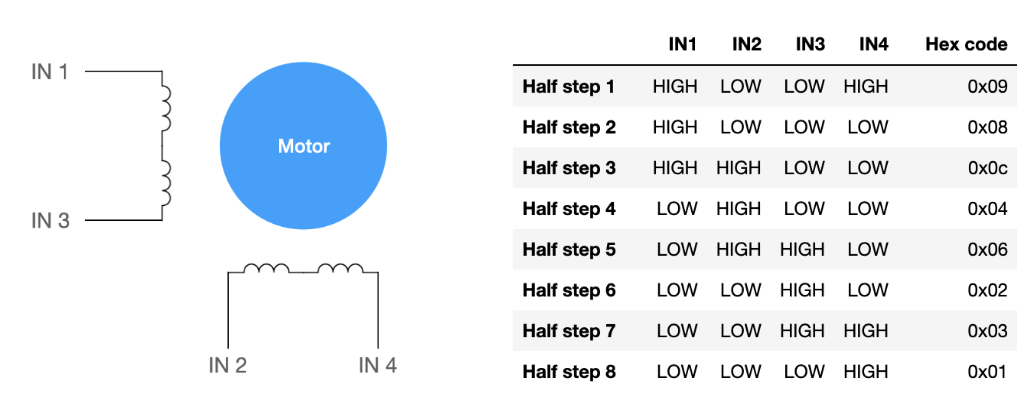
For the PIO state machine to send this pulse sequence to the GPIO pins connected to the stepper motor, a signal is waited upon from the pulse length machine and then an out instruction is used to move the data from the output shift register to the GPIOs. Note that this state machine is also fed by the DMA channel to be able to pulse the half-step sequence.
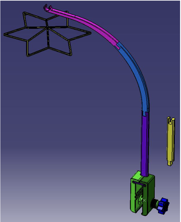
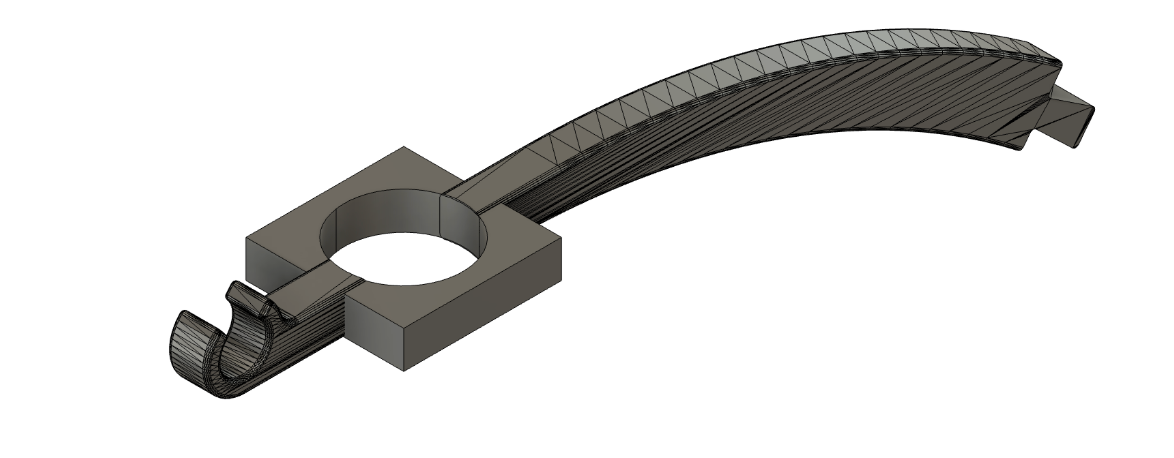
BambuStudio Printers were used to print out open-source baby mobile files to be used as the mechanical base of our project. This mechanical arm is split into multiple pieces to be printed which are later connected for a modular design. This structure consists of the part of the mobile that goes over the crib as well as the clamp which is used to secure the baby mobile to a crib. The following shows a 3D model of the baby mobile structure. Following printing out each of these pieces it was determined that an additional motor mount it was determined that an additional motor mount structure would be necessary to stably suspend the motor unit.
In the second week of the project, the stepper motor mount for the arm attachment was created and the neopixels light sequences were created.
For the construction of the mechanical arm Autodesk Fusion was used to modify the existing open-source baby mobile file. The main modification done was adding a platform to the section of the arm holding the mobile, such that in addition to having a hook another platform to stably suspend the motor above the crib while keeping the motor base fixed to avoid the possibility of tangled wires when the mobile is spinning.
In parallel to modifying the motor mount, Neopixels were worked on to get them running on the pico using C code. Neopixels fall into the family of WS2812 which is a family of intelligent control LED light source, and the WS2812 protocol requires precise timing for illumination and communication to each individual pixel of the strip. To achieve this precise timing a PIO state machine is used to reliably send signals and handle the interrupts necessary to meet timing requirements to send data to the neopixels. This control works by sending intensity values for red, greed, and blue for each pixel of the strip since each pixel contains 3 LEDs (red, green, blue) on an RGB chip which are sent data at once. To illuminate a strip, a collection of data is sent down the chain and then each neopixel LED pulls a set of data, and the rest is propagated down the chain. Timing is critical for neopixels due to their utilization of a one-wire protocol, so by using a PIO state machine precisely timed waveforms can be generated through hardware without occupying the CPU.
The PIO state machine for the neopixels works as follows, since each pixel requires 24 bits of data with (8 bits each for green, red, blue) and these bits must be sent with precise times for high and low pulses, so the PIO program outputs 1 bit at a time then checks if the bit is 0 or 1 and then generates the high/low pulse on the GPIO data pin. Timing within the program is controlled by instruction delays and through 3 timing constants of how long to keep the pin high, bit completion time, and short delay before checking the next bit.
In the third week of the project, the songs were synthesized using a similar method to lab 1 and the ultrasonic sensor was incorporated. Direct digital synthesis (DDS) is an algorithm that was used to generate a waveform using a phasor during the interrupt service routine (ISR). Essentially, a phasor is used to describe a sine wave since a sine wave could be described by projecting a rotating phasor on the imaginary axis. To implement DDS, a 32-bit integer phase accumulator can be used to represent the phase of a waveform from 0° to 360°. Each phasor is then mapped to an amplitude using a 256-entry sine table. Upon entering the ISR handler of the code, a counter, count_0, is incremented. Each time the ISR handler is entered, a fixed increment of DDS_increment (which is scaled by the full range of the phase accumulator divided by the sampling frequency 50kHz), which represents the frequency of the desired sound to be played, is added to the phase accumulator. The phase accumulator is then shifted to obtain the top 8 bits (don’t need a 232 entry sine table), which is then used to look up the amplitude of the sine wave. This process repeats until the current count reaches the total number of audio samples required to generate the desired sound.
Amplitude modulation was also used to make the sounds generated from DDS sound more natural by ramping up and down the amplitudes of the audio. This was done by multiplying the amplitudes looked up by the sine table with an amplitude envelope. The program finds the amplitude envelope by determining if the current count is within an attack time, in which the current amplitude will be incremented by a fixed attack increment. If the current count is within the decay time, then the current amplitude will be decremented by a fixed decay increment. After the phase accumulator and the current amplitude is calculated for a count, the data would be written to the DAC.
The ultrasonic sensor works by emitting a sound pulse, and then measuring the time it takes to reflect off an object and return to the sensor. The distance is calculated by multiplying the speed of sound with the time it takes for the pulse to travel to the object and then come back, then dividing it by 2 to find the distance of traveling only to the object and not returning.
Logical Structure
For this project, a Raspberry Pi Pico was used to control the different aspects of the project including lights, music, the motor, and ultrasonic sensor. As a result, different tasks were divided amongst the 2 cores of the pico for better load balancing as follows.
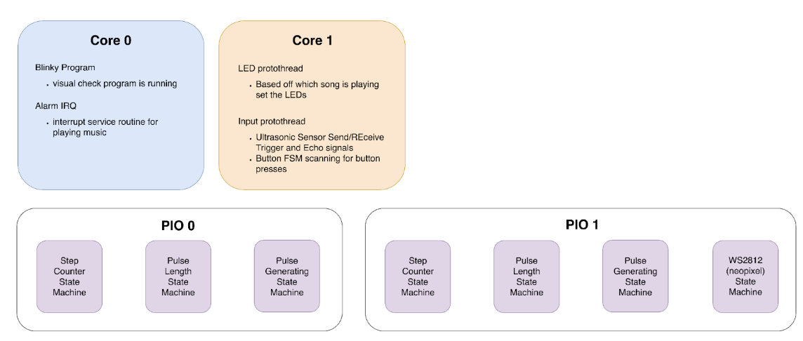
From this core 0 contains a thread to toggle the onboard LED on and off to provide better visual feedback of code being flashed to the board and functionality for easier debugging during the creation of the baby mobile. Additionally, core 0 contains timing-intensive code for the music portion of the project consisting of setting up an alarm IRQ at a frequency of 50kHz. Since music is timing intensive since human ears can easily detect when a note is slightly too long or at a different frequency than expected music was kept to its code with not much computing in the interrupt service routine to ensure that computation would be completed before the next interrupt.
On the second core, 2 protothreads were run with the first protothread being in control of the neopixels for the project and the second thread is the input protothread for sensors and peripherals to get user input (buttons and ultrasonic sensor). Note that by using the PIO for the stepper motor and neopixels, timing was no longer a major issue, therefore these aspects of the mobile were placed onto core 2.
Hardware and Software Tradeoffs
While designing Lullasky considerations for time occupying the CPU and timing, especially in regards to the Neopixels which require precise timing. As a result, a PIO state machine is used to ensure precise timing without occupying excessive CPU time. Additionally, stepper motor control was offloaded to a set of PIO machines and DMA channels to ensure proper timing of signals and less CPU time wasted on doing a repetitive constant process.
A stepper motor was chosen because of the high amounts of torque at low RPMs which is ideal for slow and smooth movement as opposed to a DC motor or a servo motor. Additionally, a stepper motor is quieter when moving which enables for a more soothing and pleasant operation.
We chose a dual powered system with both 3.3V and 5V power rails. This created two separate independent systems so that the coupling capacitance between the motor and the DAC are not correlated, resulting in cleaner music and tones outputted from the speakers. It also gave the neopixels enough current withdrawal from the dc power supply so that the entire 50 LED strip had enough current to reach every color we had specified at a decent brightness. Having to control 50 LEDs was a software choice, as we wanted a certain arrangement of light pattern across our three lullabies and so the hardware tradeoff was burning more power using the power supply, since the current outputs from any of the Raspberry Pi Pico's ports were not enough to handle all 50 LEDs.
Existing Patents
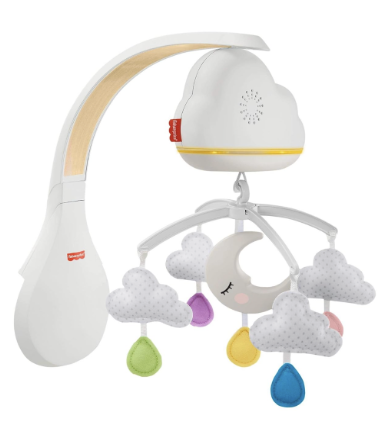
Lullasky models existing baby mobiles available on the market and contains elements of music and movement through the use of a stepper motor and audio synthesis, but also adds an interactive element using an ultrasonic sensor and bright lights to provide a baby with entertainment and joy. Currently, there are 2 main types of baby mobiles: those that dangle from a fixed arm and do not move and those that contain a motor to spin the mobile. For our project, we decided to have movement in our mobile and also add in the element of lights to make the mobile both a soothing element and an entertainment device. A device we were using as inspiration and as a model is the following baby mobile created by Fischer Price. This device contains elements that we tried to emulate including lights, music, and a spinning mobile head.