Hardware Details
The hardware system is centered around the Raspberry Pi Pico 2 microcontroller, selected for its dual-core processing and higher clock speed, which improves real-time graphics and audio performance. The hardware is designed to support video output, button and analog input, and audio synthesis—all while operating within the Pico’s GPIO and memory constraints.
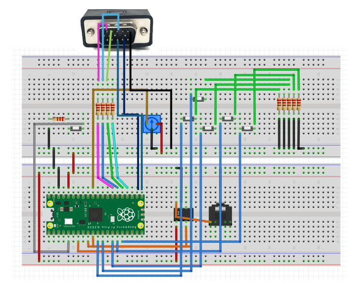
1. Video Output (VGA)
VGA output is implemented using a resistor-ladder DAC on GPIOs 16-21, with 330Ω and 470Ω resistors encoding RGB and sync signals. The RP2040’s PIO subsystem generates a 640×480 at 60Hz signal, while over 150KB of memory is allocated for the framebuffer, updated in real-time by Core 1.
Pin Assignments:
GPIO 16 → H-sync
GPIO 17 → V-sync
GPIO 18 → Green (470Ω)
GPIO 19 → Green (330Ω)
GPIO 20 → Blue (330Ω)
GPIO 21 → Red (330Ω)
2. Pushbutton and Potentiometer
User interaction is implemented through six tactile pushbuttons and one potentiometer. The buttons are connected to GPIOs 8-12 and 14 and include up, down, left, right, menu, and confirm inputs. Each button is managed with a dedicated finite state machine (FSM) in software to debounce contact bounce and prevent false triggers. These FSMs support various interaction modes across the simulation suite—for example, drawing live cells in Conway’s Game of Life, zooming in Mandelbrot, or navigating the menu.
The potentiometer is connected to GPIO 26 (ADC0) and is sampled periodically using the Pico's onboard ADC. Its analog value is mapped to control the size of the zoom frame in Mandelbrot mode. This enables smooth, continuous user control over zoom resolution, enhancing interactivity beyond discrete button input.
Buttons:
GPIO 8 → Left
GPIO 9 → Up
GPIO 10 → Down
GPIO 11 → Right
GPIO 12 → Confirm
GPIO 14 → Menu
Potentiometer:
GPIO 26 (ADC0) → Zoom size input
3. DAC and Speaker for Audio Output
Audio feedback is provided via Direct Digital Synthesis (DDS) output through an external SPI DAC connected to GPIOs 4–7. The DAC generates analog voltage levels from digitally computed sine wave samples stored in a 256-entry lookup table. An interrupt routine (alarm_irq) updates the DAC at a fixed sampling rate (50 kHz), ensuring smooth audio waveform generation.
The amplitude and frequency of the generated tone are modulated dynamically: in Conway mode, the amplitude is scaled proportionally to the number of live cells, while in Mandelbrot, tones are cycled as visual zooms are confirmed. The DAC’s output is sent to a connected speaker for clear and reactive auditory cues. This audio system enhances the user experience by reinforcing interactions with sound tied directly to system activity and simulation state.
SPI DAC Audio Output:
GPIO 4 → MISO
GPIO 5 → CS
GPIO 6 → SCK
GPIO 7 → MOSI
One approach we initially explored was using a USB mouse to control the on-screen cursor and zoom region, replacing the functionality provided by the buttons and potentiometer. While the sample code for USB mouse input functioned correctly in isolation, integrating it with our full simulation system led to a RAM overflow.
This was due to the combined memory usage of the USB stack, VGA framebuffer, and simulation logic. As a result, we pivoted to a more memory-efficient and hardware-simple solution—using GPIO-based directional buttons for navigation and a potentiometer for analog zoom control.