Hardware Design
Hardware Overview
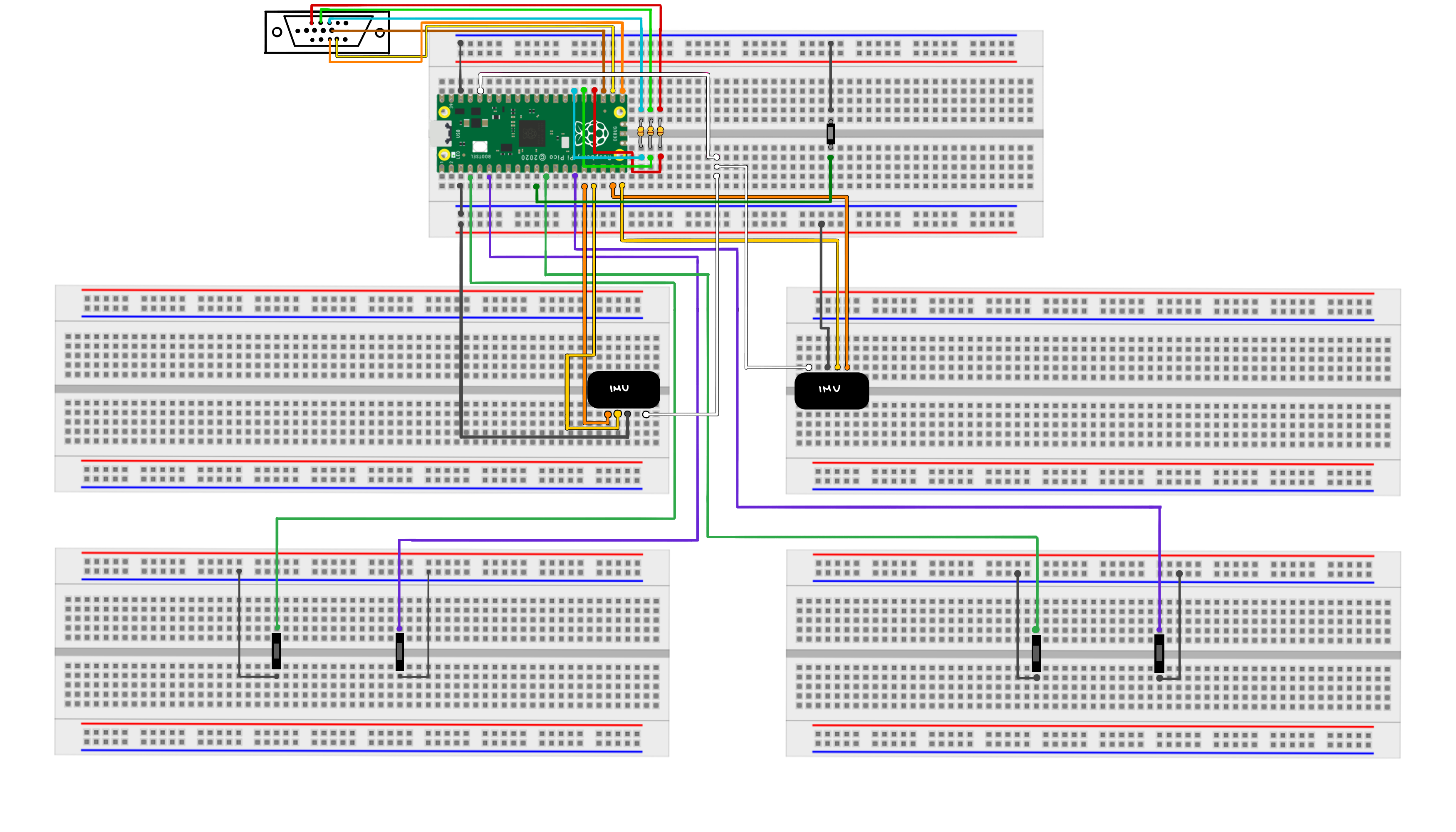
Our project is set up on a total of 5 breadboards. The center board holds the Raspberry Pi Pico RP2040, which hosts the connections between external hardware devices. Specifically, this center board was connected to the IMUs, buttons, and the VGA display wired to the RP2040 via the six connections: RED, GREEN, BLUE, HSYNC, VSYNC, and GND. GPIO pins were wired to their respective VGA pins, in addition to 330 Ω resistors connected in series to the red, green, and blue pins to limit the current entering the VGA connector. A USB cable connected the PC to the Raspberry Pi Pico to load and run our program. In particular, this board also includes the gameplay button that proceeds from the Introduction and Instruction screens, as well as restarts the game. Since there are many connections and moving parts to the game, after hardware testing, the center board was fully soldered to stabilize the connections.
Each player has their own “sword” board and button board. The “sword” consists of a full-length breadboard and a MPU6050 inertial measurement unit (IMU), ensuring that both IMU’s are oriented the same way. We used the Pico pinout diagram to determine separate I2C communication channels for each IMU; this was important because each player should be able to control their sword separately. The button board has a left and right button corresponding to the player’s movement and the placement was manually tested to find a comfortable distance between the two buttons for ease of use. Since the buttons would easily pop out while playing the game, they were also soldered to two protoboards to keep them in place and extend the longevity of the game.