
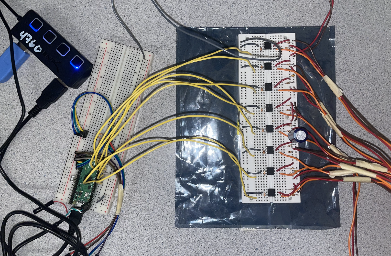
Our program starts by initializing all the hardware modules. First, we call stdio_init_all() to activate the UART module on GPIOs 1 and 2. Before any of the PWM channels are initialized, we set all of the PWM duty cycles to a value that will set the servo mallets to an upright position, since the duty cycle of a servo’s PWM input signal is what controls its position. This prevents them from moving into an invalid position if the PWM channel would be initialized immediately. Now we initialize all 8 PWM channels by following the procedure for each one:
1. Use gpio_set_function to set the pin to GPIO_FUNC_PWM
2. Calculate the slice number by calling pwm_gpio_to_slice_num and saving to an array
3. Clear and enable IRQs by calling pwm_clear_irq and pwm_set_irq_enabled, passing the calculated slice number as argument
4. Configure clock divider and wrap values by calling pwm_set_wrap and pwm_set_clkdiv, passing the appropriate values (macros) to set the period of the PWM signal
5. Configure duty cycle by calling pwm_set_chan_level, passing the slice number and channel macro (channel A or channel B) as appropriate
To set up the ISR, we call irq_set_exclusive_handler and pass PWM_IRQ_WRAP and the function on_pwm_wrap as arguments. This is enabled by calling irq_set_enabled. All the PWM channels are then enabled by calling pwm_set_mask_enabled with a mask with the bits corresponding to the used pins. This ISR is used by the PWM to check if the duty cycle value has changed and updates the output channel accordingly.
A repeating_timer struct is created and initialized with a call to add_repeating_timer_us with the arguments -1000 (denotes a 1ms timer that requests interrupt immediately), repeating_timer_callback (set up the ISR function), and &timer (tie it back to the struct). This timer is used to handle the timing between beats and determine when a servo mallet should strike the key based on the song’s data.
Our program consists of two protothreads, one thread for handling serial input via a UART interface and one thread for handling the state machine associated with each servo. Protothreads is a non-preemptive threading library written by Adam Dunkels and ported to the RP2040 by Bruce Land. The threads contained within the functions protothread_serial and protothread_play are added to the scheduler by passing them as arguments to the function pt_add_thread and the scheduler is started by calling the macro pt_schedule_start.
To support our program, we have a handful of global variables. An array slice_num is initialized as described previously and stores the PWM slice number associated with each servo, an array XYLO_STATE that stores the state (either WAIT, STRIKE_DOWN, or STRIKE_UP enums) for each servo, a const array that stores the channel macro information (PWM_CHAN_A and PWM_CHAN_B alternating), two more const arrays UP and DOWN that store the PWM values that we have calibrated for the servo resting and servo hitting positions, and two last volatile arrays control and old_control for storing the current and past PWM duty cycle values. The other global variables we have are two volatile uints that store the current counter and beat values for song timing, and a volatile pointer (type song_t*) that stores the current song.
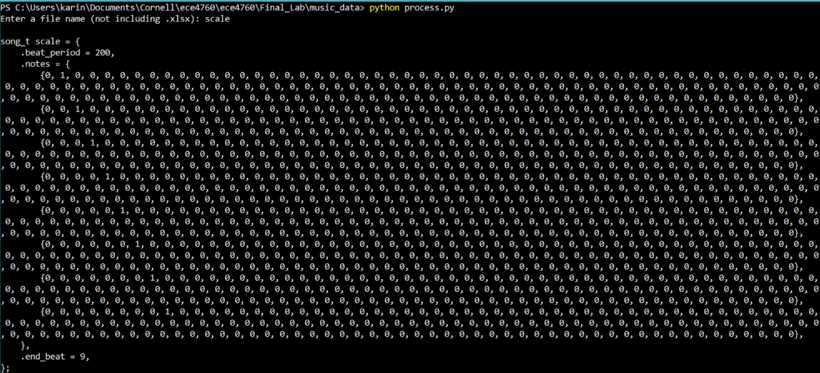
The header file music.h provides most of the definitions solely related to our song storage system. There are macro definitions for common values such as MAX_LEN (maximum beat length of any song), NUM_SERVOS, and NUM_SONGS. Here we also define our custom struct type song_t that contains the beat_period and end_beat values, and a two-dimensional notes array that is of size NUM_SERVOS by MAX_LEN (currently 8 by 160). The last thing the header does it provide some externs so that we can provide our main program xylophone.c with variable names but include the definitions in music.c. These include extern song_t types for each of our songs and an extern song_t* called song_list so we have an array of pointers to each song (having the pointers in an array makes it much easier to store and load song data). The organization of the song data is discussed later, but music.c includes an element definition of song_list ({a, b, c} format) and in-place struct definitions of songs ({.a=1, .b=2, .c=3} format).
When the timer ISR repeating_timer_callback is called, it starts by increasing the counter variable. This counts how many milliseconds have passed. If curr_song is a valid pointer (not NULL, therefore a song is loaded/playing) and the counter’s value is greater than the current song’s beat_period, we want to play the next note. So on this condition, we reset the counter to zero and do one final check to make sure that the loaded song has a valid beat period (non-zero). If that checks out, we loop through all 8 state machines and transition each one to the STRIKE_DOWN state only if the corresponding beat is set true in the corresponding note array. We then increase the beat counter and the process repeats again once the counter reaches the beat period again. If the beat counter is greater than the number of beats in the song, we know the song has finished playing and so we reset the beat counter and set the current song pointer to NULL to signify this.
The PWM ISR on_pwm_wrap serves to update the PWM duty cycle for each servo asynchronously from the state machine triggers. The function first loops through all channels and checks if the duty cycle for that channel (stored in control) has been updated (by comparing it to old_control). If so, it saves the value (into old_control) and sets the duty cycle by calling pwm_set_chan_level and providing the slice number, channel macro, and duty cycle as arguments. After all possible changes have been made, all of the IRQs are cleared by calling pwm_clear_irq on the slice number (this will clear each of the four slices twice, but has no negative effect).
Our serial protothread is very similar to that of previous labs. It starts by printing out all the available options (in our case, what songs are available) to the pt_serial_out_buffer and calls the protothread macro serial_write to provide non-blocking printing. A while(1) loop then calls the non-blocking read macro serial_read to wait for serial input, then calls sscanf with the format character %d to read integers. Once a valid number is provided, the current song pointer is set to the appropriate song pointer in the song_list array.
Our music playing protothread provides the rest of the state machine transitions and functionality besides the initial transition provided by the timer ISR. It loops through all the servos and performs the following checks before yielding to the serial thread:
1. If in the STRIKE_DOWN state, set the PWM value to the corresponding value in DOWN to strike the note and transition to the STRIKE_UP state.
2. If in the STRIKE_UP state and the counter is greater than 70 (number of milliseconds elapsed since the beat began), set the PWM value to the corresponding value in UP to release the note and transition to the WAIT state.