Introduction
Nowadays, robot hands are everywhere. They don’t just serve as a toy to be played with, but also exist in educational and industrial sectors. The best thing about robot hands is that they can never get tired or injured. They can help us with repetitive and mundane tasks and can operate in conditions that human cannot stand. These characteristics make them perfect for completing tasks in extreme conditions. But the challenge of using a robot hand is that it is very difficult to operate it exactly the way we want. More specifically, we cannot control its fingers like we control ours, which limits its ability to complete delicate tasks. This led us to think if we can build a robot hand that can precisely follow our movements.
Inspired by this idea, our final project is to build a robot hand that can mimic human fingers’ movements. To accomplish this goal, we designed a control glove that collects curvature data from a set of flex sensors and transmits this data via a transceiver to the robot hand. The microcontroller connected to the robot hand then maps this curvature data to the corresponding duty cycle and thus controls the servo movement using PWM. We will discuss the technical details in the following sections.
High level design
The purpose of the project is to build a robot hand whose actions could be controlled wirelessly by a sensor glove. The implementation consists of three major parts: assembling a 3D-printed robot arm whose gesture would be controlled by servos, soldering flex sensors to fingers of the sensor glove which would be connected to GPIO ports of a RP2040 microcontroller, and establishing wireless communication between the glove and the robot arm with nRF2401 transceivers. The required hardware components are listed as following and the 3D printing arm parts prototype could be referenced in the following website:
| Components | Quantity | Shopping Website |
|---|---|---|
| Raspberry Pi Pico | 2 | From lab |
| nRF24L01 + Transceiver | 2 | Amazon |
| Servo motor | 5 | Amazon |
| Flex sensor | 3 | Adafruit |
| Glove | 1 | Amazon |
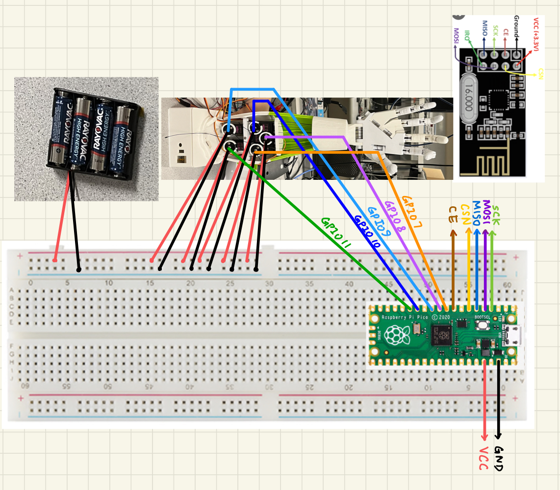
In particular, three flex sensors have been used to measure the amount of deflection of the sensor glove’s fingers. As flex sensors function as variable resistors, we created a voltage divider circuit with 10k resistors for each of the flex sensors. To be more specific, the GND end of the all flex sensors are connected to the GND port of the Raspberry Pi Pico, and the + 3.3 V from the Raspberry Pi are connected to the main positive voltage wire of the voltage divider circuits. The wire from the other end of each flex sensor is connected to separate Analog-to-Digital GPIO ports – 26, 27, and 28 – to reflect how much each flex sensor bends. The specific connection could be seen in Figure 1.
The digital signal of the flex sensors is then sent to the other Raspberry Pi Microcontroller utilizing the NRF24L01 transceivers. The transmitter and receiver logic was implemented referencing the following open-source library. This library provides the user with functions that associate the pins of the transceiver – CE, CSN, etc. – to the appropriate GPIO ports of the Raspberry Pi microcontroller. It also allows the users to configure and initialize NRF24L01 transceivers and transmit multiple signals using various data pipes with simple functions. In the project, we transmitted three data pipes – each associated with one finger – at an air data rate of 5Mbps and address width of 5 bytes.
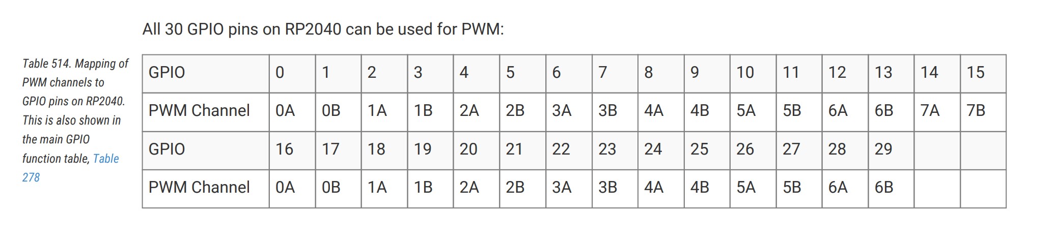
As the digital signal of the flex sensor has been transmitted from one microcontroller to the other, it would be used to set the servos motor voltages of the robot hand at appropriate values so as the control the fingers’ movement. In setting the motor voltage, the scheme PWM – a process that turns a digital signal into a smoothly varying average voltage signal by altering the on and off periods – was utilized. The term, duty cycle, describes the fraction of time spent high and is connected to the receiver signals. The duty cycle was set with the function pwm_set_chan_level(). Noticeably, the RP2040 PWM block possesses 8 identical slices, while each slice possesses the ability to drive two PWM output signals. Slice 3, 4, and 5 were utilized in the project. Noticeably, there is a balance of hardware and software design in the project, and all the open source libraries that we have used are listed in the appendix.
Software design
We implemented two separate program logics in the project design, one for each of the Raspberry Pi Pico Microcontrollers. Both program logics set up two threads. In the transmitter logic, the protothread_adc thread consistently reads the digital signal of the flex sensors and stores the value in the global variables; the protothread_transmitter thread consistently sends such signals to the receiver on the other Raspberry Pi Pico Microcontrollers. In the receiver logic, the protothread_serial thread consistently receives the data sent by the transmitter and stores the value in global variables, while the protothread_pwm thread consistently checks the status of flex sensors with such global variables and sets the motor voltages accordingly.
The communication between the two microcontrollers was achieved through NRF24L01 transceivers. In implementation, we first set up the GPIO pins according to Table 2 and initialize the device with desired settings. Specifically, we set the air data rate to be 5Mbps and address width to be 5 bytes, which corresponds to a baud rate of 10000000. We used a RF channel of 110, as WiFi uses most of the lower channels. Then, we define three separate dynamic data pipes to store transmitting signals, set a unique address in buffer to the specified data pipes, and switch the NRF24L01 from the Standby-I mode to RX/TX Mode. Eventually, we call function – nrf_driver_send_packet(const void *tx_packet, size_t size); – to send the data packet on the TX side and call function – nrf_driver_read_packet(void *rx_packet, size_t size)– to receive the data packet on the RX side.
Through experimentation, it is determined that the flex sensor presents a digital value around 50 when held straight and a digital value around 150 when held bending over. As a result, we would set the duty cycle as 2000 – corresponding to robot arm finger bending down – when the signal of the flex sensor is detected to be lower than 100. On the other hand, we would set the duty cycle as 1000 – corresponding to the robot arm finger straight up – when the signal of the flex sensor is detected to be bigger than 100.
Hardware deisgn
We will discuss the design of our hardware in two parts: the robot hand and the control glove.
Robot hand
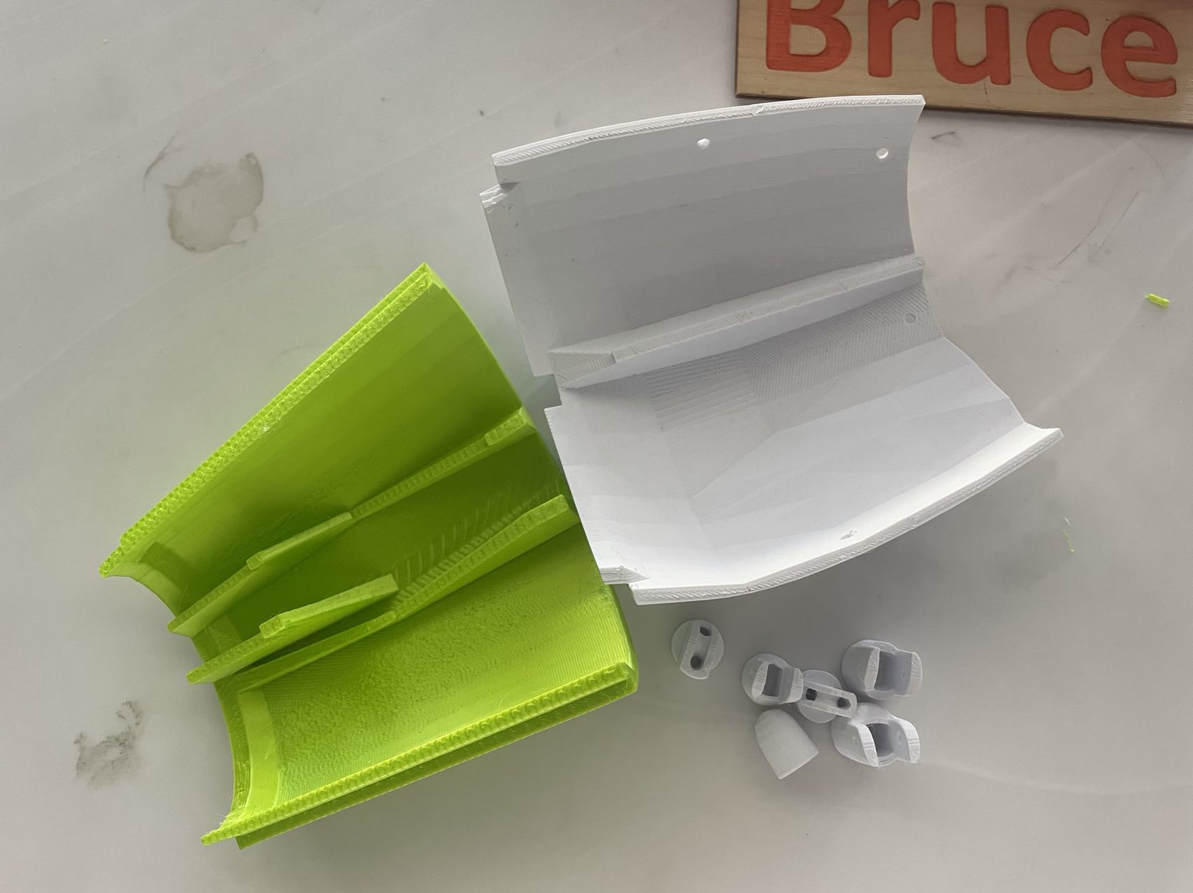
Our entire robot hand is 3D printed using PLA material. PLA is known for its high strength, low thermal-expansion, and non-toxic nature and is easily accessible in labs. These properties make PLA ideal for 3D printing. For the individual components of the hand, we used models from an open-source website—InMoov—with slight adjustments in the wrist. Table 1 shows all the components and corresponding cost. When printing these components, we chose an infill of 20% to ensure the hand is robust enough to withstand external force. After printing was completed, we assembled them using epoxy glue. For each finger joint, we inserted short strips of filament and electrical wires to fill the holes.
| Part | Price($) |
|---|---|
| Forearm 1 | 1.84 |
| Forearm 2 | 2.08 |
| Forearm 3 | 2.38 |
| Forearm 4 | 1.6 |
| Little finger | 0.21 |
| Thumb | 0.6 |
| Ring finger | 0.27 |
| Index finger | 0.3 |
| Middle finger | 0.35 |
| Bolts | 0.29 |
| Hand covers | 1.13 |
| Servo wheels | 0.26 |
| Servo stand | 1.33 |
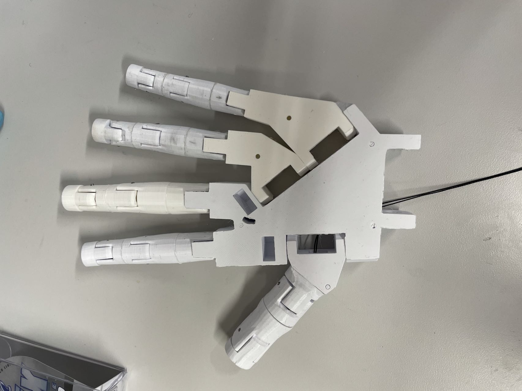
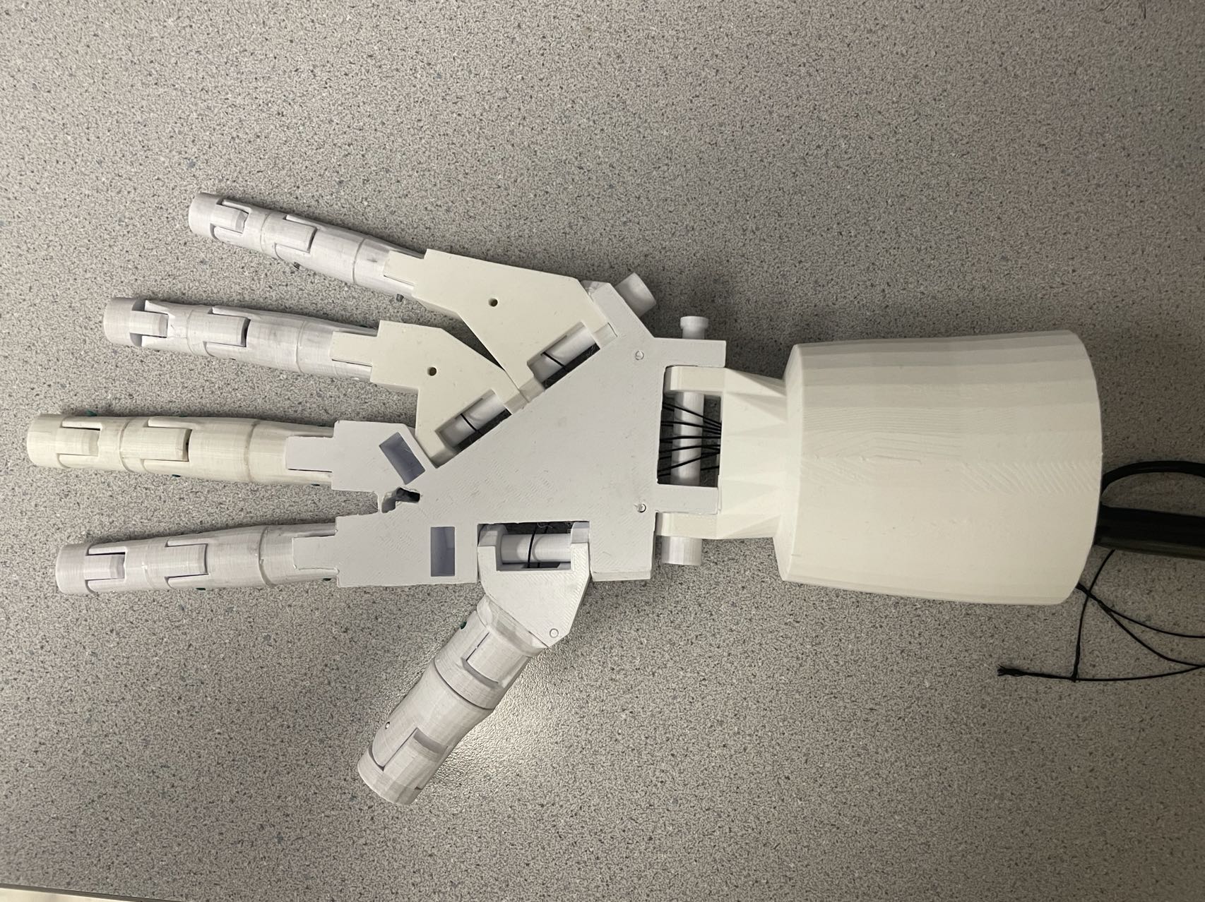
The movement of the fingers are achieved by pulling on the wire that goes through each joint. We used braided fishing wire to link the fingers together as it can withstand a relatively large amount of force, which is necessary considering that the MG996R servo motor can exert up to 11 kg/cm of stall torque. The wires are routed to the wrist of the robot hand and wraps around a servo wheel. After the mechanical side of the robot hand was complete, we started adding on servos. Each of the five servos is responsible for controlling one finger. These servos can rotate their shafts within a range of angles and by defining the duty cycle of the pulse-width modulation, we can explicitly turn them to a certain angle. Referencing the datasheet, we know that the MG996R servos take in a PWM signal of 50Hz and the on-time can vary from 1ms to 2ms, corresponding to 0 to 180 degrees. Given the raspberry pi pico’s default frequency of 125MHz, we calculated a new warp value of 20000 and a clock divide value of 125 to achieve a resultant frequency of 50Hz. These two values are carefully selected so that 0.001 and 0.002 are both integer multiples of the reciprocal of 125MHz/warp value. We allocate the selected GPIO explicitly for the PWM function using the gpio_set_function. Then, we set up PWM’s wrap value and divide value to the two numbers we found before. The last step is to select an initial duty cycle and enable the PWM channel. To test the actual behavior of the servos, we connected their signal pin to a GPIO on the raspberry pi pico and observed the reaction of the servos when PWM channel level is setted to 1000 and 2000 respectively. Using this method, we found that the fingers are straight when the duty cycle is set to 1ms and curls up when set to 2ms. The behavior of the thumb is reversed due to reversed wire connection. When testing the entire robot hand circuit, we initially powered the servos by wiring its power pin to VBUS of the raspberry pi pico, and the pico itself is powered by connecting to a computer. The VBUS pin directly connects to the 5V input from the micro-USB port and should provide 5V power to the servo. However, our computer reboots every time the code runs. We suspect this happens because the servos are drawing too much current from the computer, which causes it to go to sleep. To address this problem, we used a battery case with 4 AA batteries to externally supply power to the servos.
Control glove
On the control glove side, the goal is to collect curvature data from the flex sensors and send them to the robot hand using a transceiver. Under the hood, the flex sensors work as variable resistors. By connecting them in series with 10K resistors and connecting wires in between to ADCs on the microcontroller, we can determine the change in voltage level which reflects the bending of flex sensors. When the flex sensors are bent, the materials inside get close together and the resistance increases.
However, during the actual implementation, we found that the flex sensor readings fluctuates a lot when applied a small force. The correlation between bending angle and flex sensor readings are not always the same, and after bending the sensor a few more times, the values take longer and longer to change when the flex sensor is straightened up. We also found that the flex sensor readings wrap around when the sensor is bent past a certain angle, which sometimes causes incorrect behavior. After setting up the flex sensor circuit on the glove, we found that the robot hand will consistently and randomly twitch, which makes the whole system very unstable. Some of the potential causes of this behavior include the inherent angle of the glove and the extreme sensitivity of the flex sensors. After a few more experiments, we unfortunately had to give up using the glove and instead control the fingers by manually bending the flex sensors.
Conclusion
Overall, our project successfully fulfilled the initial proposal. The core of our project, wireless control of the robot hand, functioned well in the sense that the robot fingers will move accordingly as the bend of flex sensors. Even when multiple flex sensors are bent simultaneously, the delay of robot fingers’ movement is negligible. In terms of safety relating to our system, we set the lower and the upper bound for the turning degree of servo motors to make sure the hardware will not break. Moreover, to ensure security of our mechanical hauling system, we choose to use the fishing thread that could sustain 30 lb to connect all joints of the robot finger with the servo motor.
According to users’ feedback, there are still some drawbacks of our system that need to be improved in the future. First and foremost is the hardware problem. After attaching the flex sensors onto the glove, the data collected will sometimes be inaccurate and fluctuate, causing the incorrect movement of robot fingers. This problem can be caused by either inappropriate attachment method of flex sensors to the glove, or by the possible damage of flex sensors.
Another improvement we can make is that we currently only enable three flex sensors to work simultaneously, because there are only three ADC channels on the Raspberry Pi Pico board. To control all five fingers together, the on-time of the PWM for the servo connected to the little finger is determined by the same ADC channel used for the ring finger, and the movement of thumb is set to be same as the index finger.
Lastly, the flex sensors are too sensitive that they sometimes send incorrect sensor data when bended slightly. When the sensors are bend over a certain angle, the value also wraps around. This could cause redundant back and forth movements of robot fingers. The proposed solutions to the above drawbacks will be discussed in the next section.
Solution and improvements:
To address the above three main drawbacks, here are what we could do in the future:
(1) Modify the way we attach flex sensors to the glove. Instead of only fixing two ends of the flex sensor, we could design a cover for the flex sensor and fix the cover to the glove, enabling the sensor to fit tightly with the glove.
(2) Use mux in our design. This way we can select multiple inputs to one ADC channel, and we could receive and convert data from five flex sensors and control the five fingers independently.
(3) Adding an average function in our code. This function is responsible for taking average of received sensor data over a short period of time and determine the movement of robot fingers. In this way we could reduce much of the back and forth movement because of a few inaccurate data.
Intellectual Property Consideration:
Our design of robot hand is based on the open-source project called inMoov, including most 3D-printing files and the instructions for assembling the robot hand. This platform is available to everyone and thus using their design does not violate any intellectual property rights. We referred to the public Github repository of AndyRids for using the nRF24L01+ transceiver with raspberry pi pico.
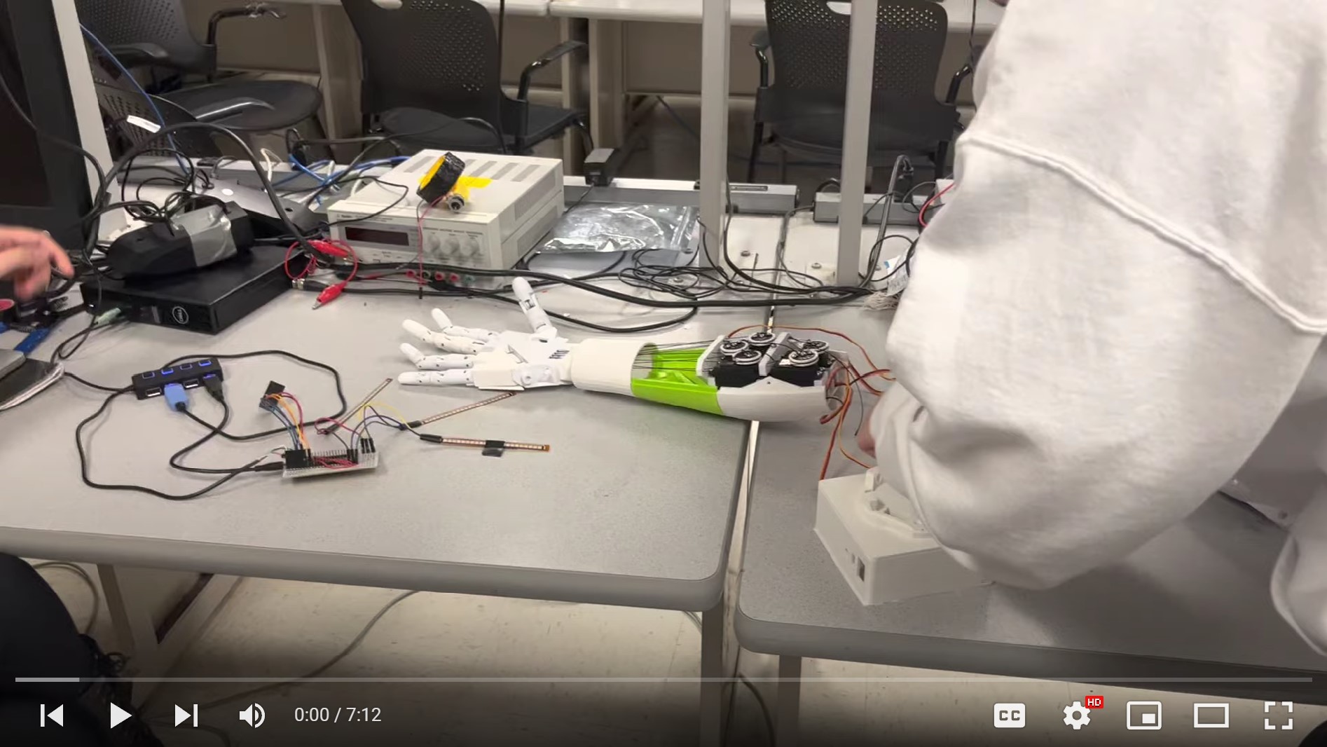
Final demo video
Appendix
The group approves this report for inclusion on the course website.
The group approves the video for inclusion on the course youtube channel.
References: