Game of 24
Sean Zhang (swz9), Ray Chang (cc2246), Shizhe Shen
(ss4335)
Demonstration Video
Project Introduction
Our digital recreation of the Game of 24 brings the classic arcade experience with a custom interface that blends nostalgic gameplay with a custom built, user-experience focused design.
The Game of 24 is a classic mathematical puzzle where players must use four given numbers and basic arithmetic operations (+, -, *, /) to form an expression that equals 24. Traditionally the game is played with a deck of cards, where each turn the players will draw four random cards and compete for the fastest speed to calculate to 24. Instead of racing to solve a single round, our implementation tracks the number of collections of cards solved within a configurable time interval.
The arcade experience is curated with a custom built joystick-based controller, retro-style graphics with the VGA screen, and a persistent leaderboard stored in non-volatile memory. The game is player vs player similar to the versus style arcade games. Difficulty can be adjusted at run-time and a group of 4 numbers of the suitable difficulty are calculated at runtime. Card dealing, flipping animations and sound feedback contribute to the immersive experience.
High Level Design
Rationale Behind Implementing the Game of 24
We chose the Game of 24 because it’s a fun, classic puzzle that we personally enjoy, and it offered a great mix of hardware and software challenges. It allowed us to go beyond a basic game, turning it into a feature-rich product with a custom interface, optimized performance, and room for additional features. This project gave us the freedom to transform a simple concept into a polished, well-developed game.
Hardware/Software Tradeoffs
Our implementation of the Game of 24 uses both cores on the microcontroller, with each core dedicated to managing the gameplay experience for each player.
On the hardware side, each core of the microcontroller is tasked with managing the joystick input, rendering animations, and updating the VGA display for its assigned player. This parallel processing ensures that each player’s actions are processed without interference, providing a smooth and responsive experience. The use of multiple cores for real-time input and display updates significantly reduces latency and allows both players to interact simultaneously without any noticeable delay. However, this multi-core approach introduces some software complexity. For shared memory, concurrency protection mechanisms such as locks and semaphores are used to prevent any undefined behavior.
Software Design
Algorithm for Generating Solutions
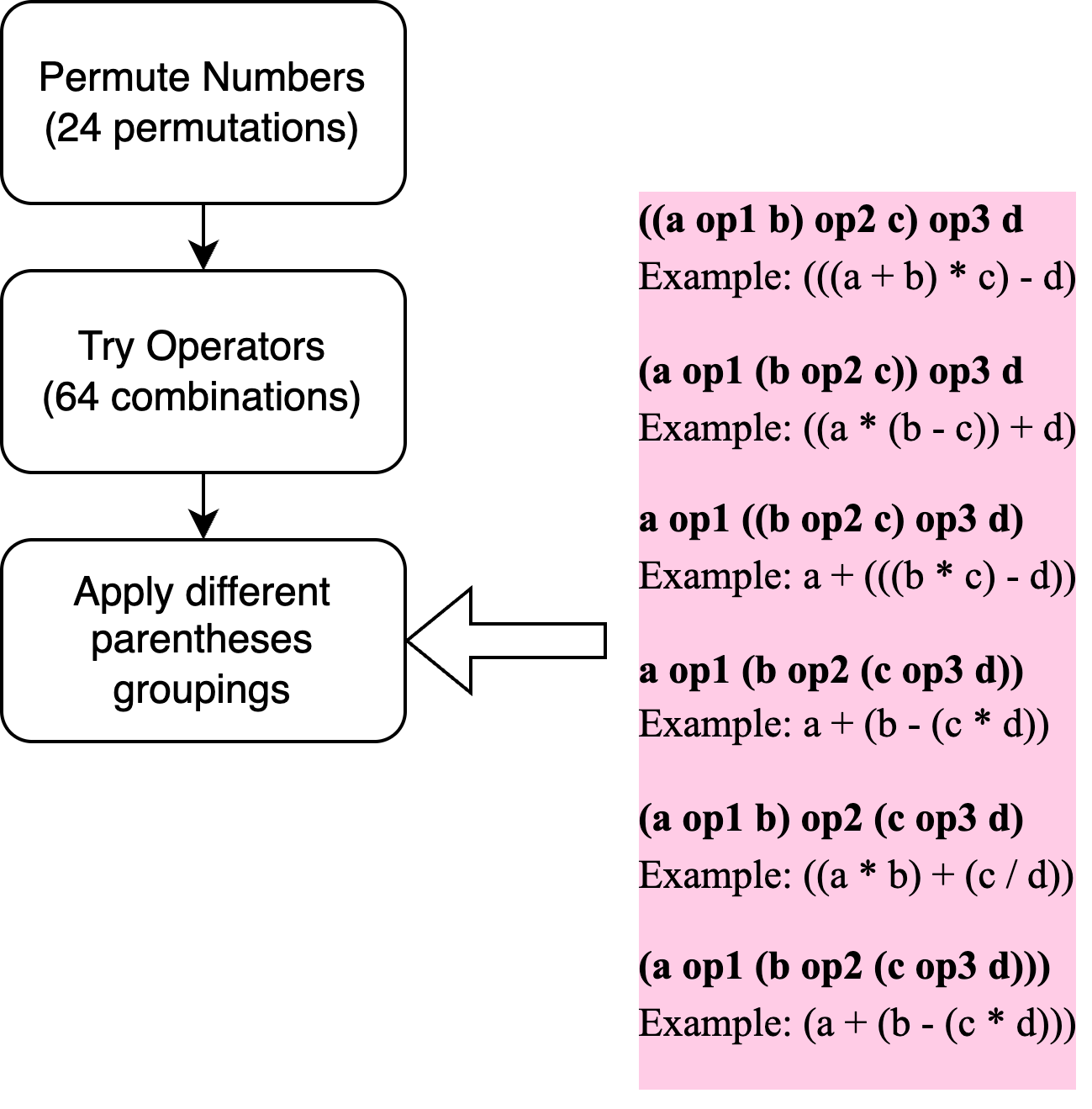
The core idea behind the 24-point solver is to exhaustively evaluate all valid arithmetic expressions formed from a given set of four integers. The algorithm applies the basic operations +, -, *, and /, and explores all permutations of the numbers (4! = 24), operator combinations (4³ = 64), and six distinct parenthesis patterns that define evaluation order. Each configuration is numerically evaluated to check whether it equals 24 (within a small epsilon tolerance), ensuring that all mathematically valid solutions are captured through brute-force enumeration. To implement this algorithm, we began with an open-source solver, which determines whether a solution exists for a given set of four numbers. I then extended the code to output all valid expressions rather than just confirming existence. Additional improvements included filtering out duplicate solutions, avoiding intermediate negative values, and counting the number of unique solutions. I also introduced a difficulty rating system (easy, medium, hard) based on the number and complexity of solutions, and added functionality to generate random problem sets matching a specified difficulty. These enhancements made the solver both comprehensive and adaptable for dynamic puzzle generation within the game.
Efficiently Drawing Images to the VGA Screen
Images are needed for displaying cards and the 24-logo.
A Python script that converts an image into a 2D C array suitable for VGA rendering. This script uses the Python Imaging Library (PIL) to open the image, resize it according to specified width and height ratios, and then iterates over each pixel. For each pixel, it maps its RGB values to a corresponding 4-bit color value. The resulting 2D array stores these color values, and the script outputs the array in a format directly compatible with C, making it ready for use in VGA rendering.
Initially, we displayed assets on the VGA screen by iterating through each 2D C array, calculating,
and
setting each pixel individually by setting the upper 4 or lower 4 bits of the
vga_data_array.
However, this approach proved too slow when sliding or flipping the image.
To optimize, we leveraged the fact that each row of the 2D array is memory-aligned. By using
memcpy,
we
can copy entire rows at once, achieving 32-bit transfers—effectively drawing 8 pixels at a time.
This
method provides an 8x speed improvement.
Given a desired x, y position and the current row i of the
asset we are trying to copy, the index in the vga_data_array to begin copying to is
calculated as
vga_index = ((y + i) * 640 + x) >> 1. The (y + i) * 640 calculates the
starting index of the ith row for a 640-pixel wide screen. The addition of x shifts the
position from the left edge of the screen to the desired x-coordinate. The right shift by 1
operation is required because each byte in the vga_data_array can store two pixels
(4-bit color). The right shift by 1 effectively divides the index by 2, converting the pixel index
to a byte index.
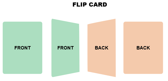
Flip Animation
The flip animation is based off of the following image. During the first half of the flip, the image will be stretched to a trapezoid shape with the left edge as the longer base and the right edge as the shorter base. The height of the trapezoid will decrease as the flip progress approaches the halfway point. The trapezoid will then be inversed and the right edge will become the longer base and the left edge will become the shorter base. The height of the trapezoid will increase as the flip progresses to the end of the animation.
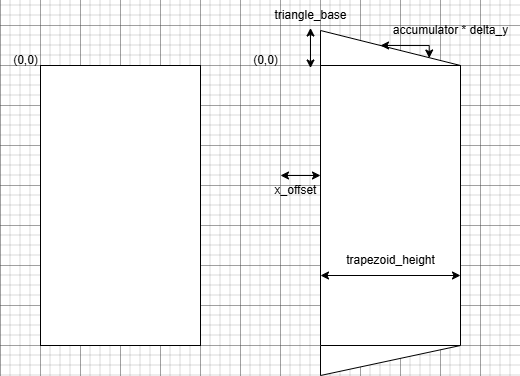
The trapezoid is split into the upper right triangle, lower right triangle, and the central
rectangle. Parameters such as the height of the left and right bases and the width of the trapezoid,
are mapped to values based on the progress of the flip. The top triangle is drawn with the below
code. The drawHLineCustom(..) function is based
off of the drawHLine(..) function in the VGA library. Instead, it draws a custom asset
instead of a solid color. The triangle is drawn starting from the top left of the triangle. As the
loop iterates,
horizontal lines are drawn from the left edge to the right edge of the triangle. The length of the
line drawn is dependent on the accumulator variable. The accumulator is
accumulated by triangleStep, which is the
the quotient between the trapezoid height and the triangle base. This is effectively the slope of
the triangle's hypotenuse. The x_offset addition is used to shift the triangle to the
right as the trapezoid's height decreases.
The middle rectangle is drawn with the line
pasteImage(top_image, image_height, trapezoid_height / 2, x + x_offset, y, bg).
top_image is a pointer to the asset. The image_height is the height of
the asset. The x + x_offset and y arguments are the top left x and y
coordinates of the image to paste.
The bottom triangle is drawn with similar logic to the top triangle. Since we still draw from the
top left of the triangle, the accumulator starts at the full trapezoid_height and
decreases.
During the second half of the flip, the same logic largely applies. The right base of the trapezoid grows while the left base shrinks. The trapezoid's height increases instead of decreasing.
Sound Effects
We incorporated sound effects into the 24-point card game, improving input feedback and immersion. Key moments were mapped to distinct audio cues such as start menu and card selections, card dealing, and flipping.
While the DDS-based method in that file worked for simple tones, it was unsuitable for realistic sound effects. Instead, .wav files—originally sourced as .mp3, trimmed for timing, were converted into C arrays for inclusion in header files. These assets could then be triggered from the animation logic.
The initial playback method used a timer interrupt with SPI, which worked well when tested in isolation through serial-triggered playback. However, once integrated with the main animation code, the high interrupt frequency (8–44 kHz) conflicted with timing functions like sleep_us(), resulting in frame delays and visual stuttering. Additionally, SPI transfers suffered from jitter under load, causing popping artifacts and inconsistent playback.
After consulting with our instructor, Hunter Adams, a DMA-based method using Lab 1’s e_DMA_demo as a starting point. This resolved the timing issues by offloading audio streaming from the CPU. During early testing, I encountered silence due to a mismatch in audio output channels—beep_beep.c used channel B, while dma_demo.c defaulted to channel A. Once corrected, the DMA method produced clean, uninterrupted audio.
Moreover, DMA enabled a solution to another limitation: memory overflow when embedding long sound clips. By splitting .wav files into smaller fragments and using chained DMA descriptors, I could loop short buffers to simulate longer sounds without exceeding memory constraints—something timer-based methods couldn’t handle.
Finally, sound was integrated into the core gameplay logic. Some animations, like card dealing, were implemented within infinite loops and used flag-based control. Naïvely calling sound triggers within these loops caused repeated DMA reconfigurations. To prevent this, we added logic to play each sound once at the start of an animation sequence, suppressing repeated triggers until the animation completed. Additionally, to preserve sound quality, we adjusted the DMA sampling rate for each clip based on its original audio. For example, the flipping sound required ~11.025 kHz instead of the default ~44 kHz..
Game Code Structure
The game software is split across two cores. Within both cores, two threads handle inputs and VGA animations. On core 0, an additional thread waits for a semaphore signal to begin a serial listener for leaderboard inputs. On core 1, a timer callback ISR executes every second to decrease the seconds remaining during the main gameplay loop.
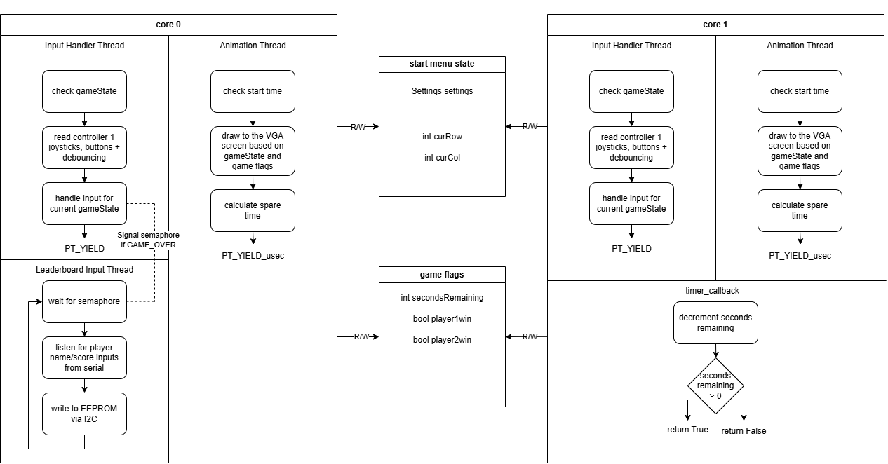
The input thread in each core is responsible for reading the joystick inputs and button presses.
Debouncing is implemented to make button presses and joystick inputs more reliable.
Based on the current gameState, it will execute different actions based on the joystick
and button inputs. For instance, if the game is in the START_MENU state, joystick and
button inputs will set the game settings, or start the game based on the
current selection of curCol or curRow. In the GAME_PLAYING
state, inputs signal arithmetic operations, reset requests, or redealing a new set of cards. Inputs
in the GAME_OVER state determine whether the player wants to save a score to the
leaderboard.
The animation thread in each core is responsible for rendering the game graphics on the VGA screen.
Based on shared game flags and the gameState, the animation thread will draw the start
menu, main game screen, or game over screens. Animations such as flipping cards and sliding cards
are also handled within this thread.
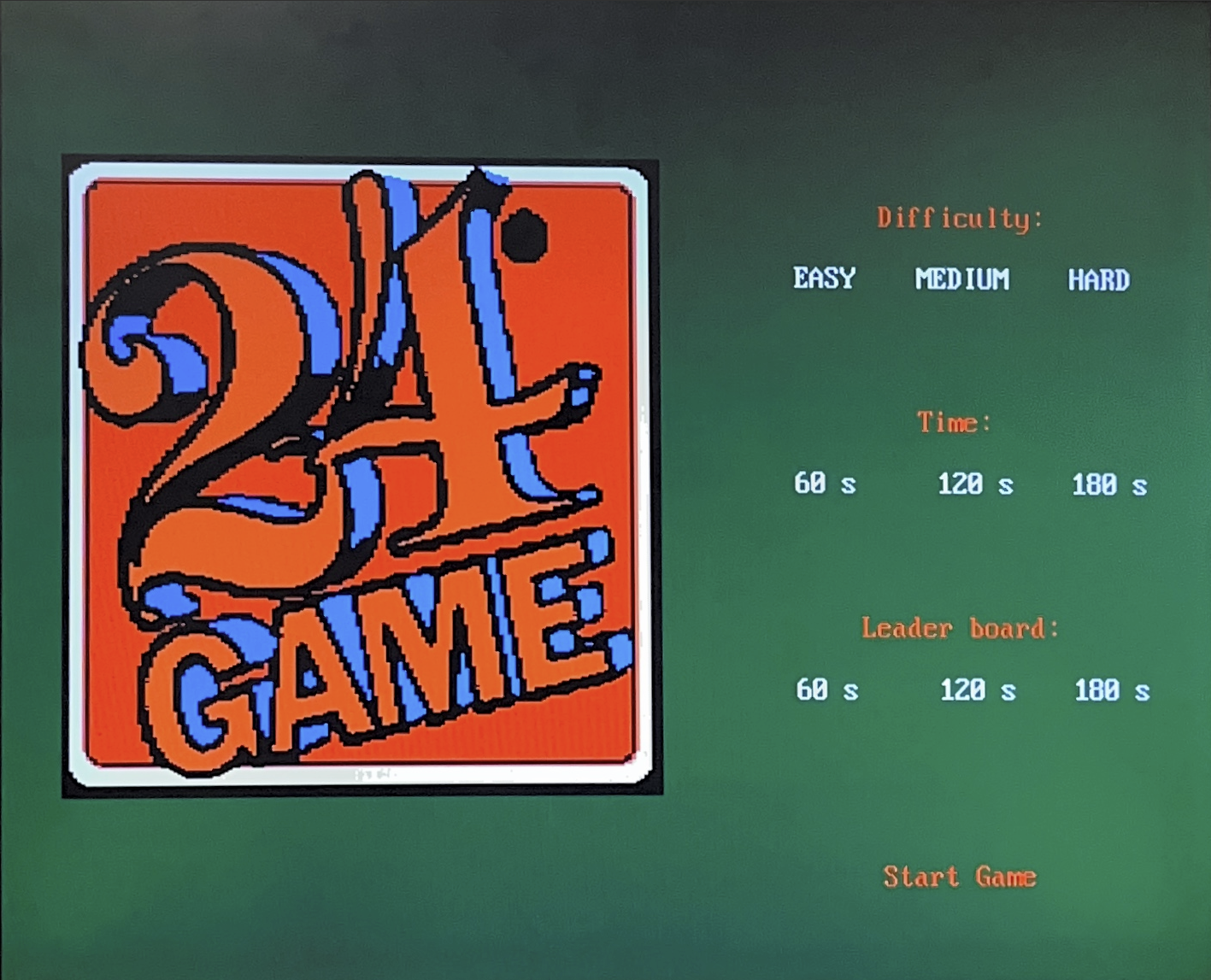
START_MENU screen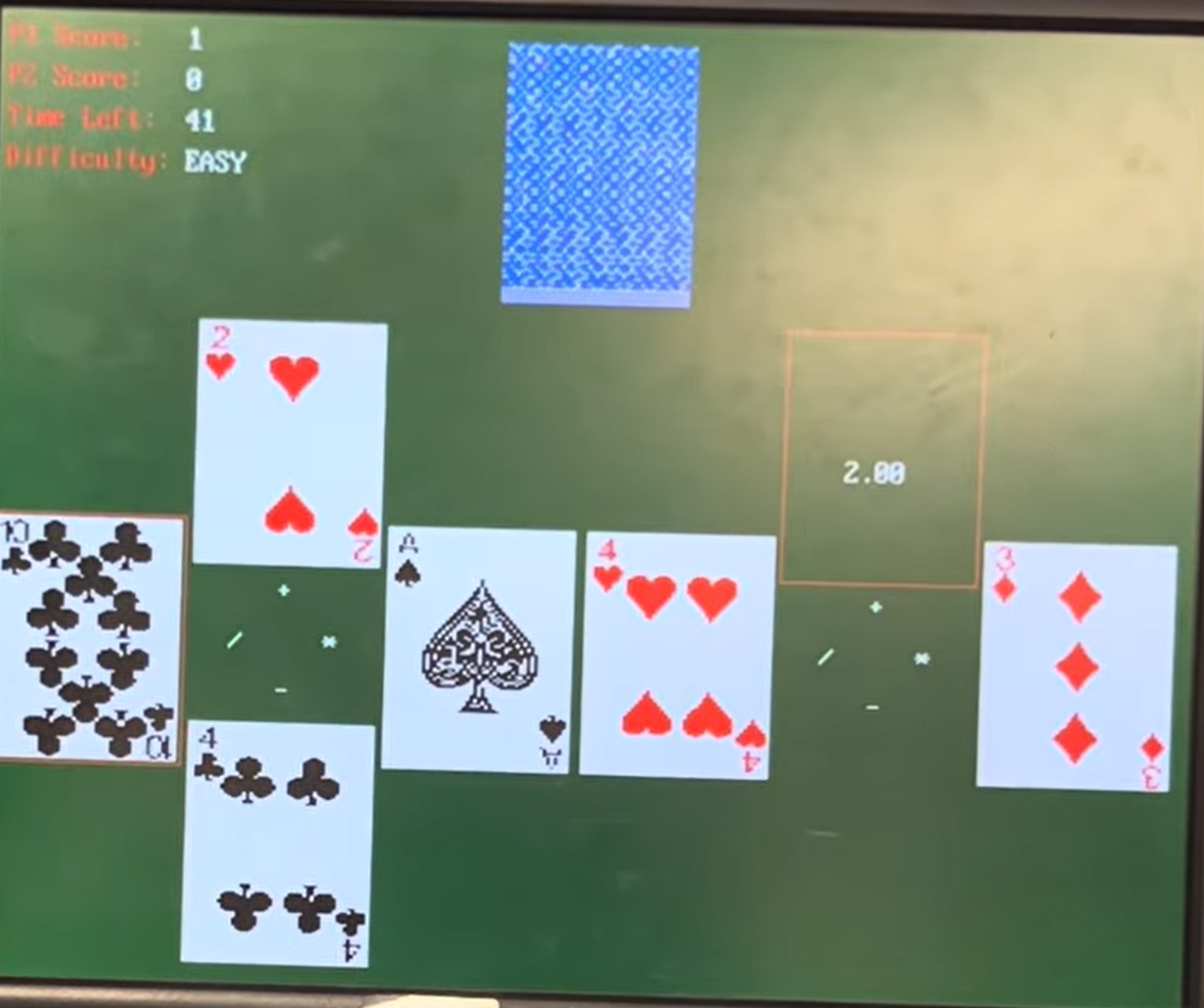
GAME_PLAYING screen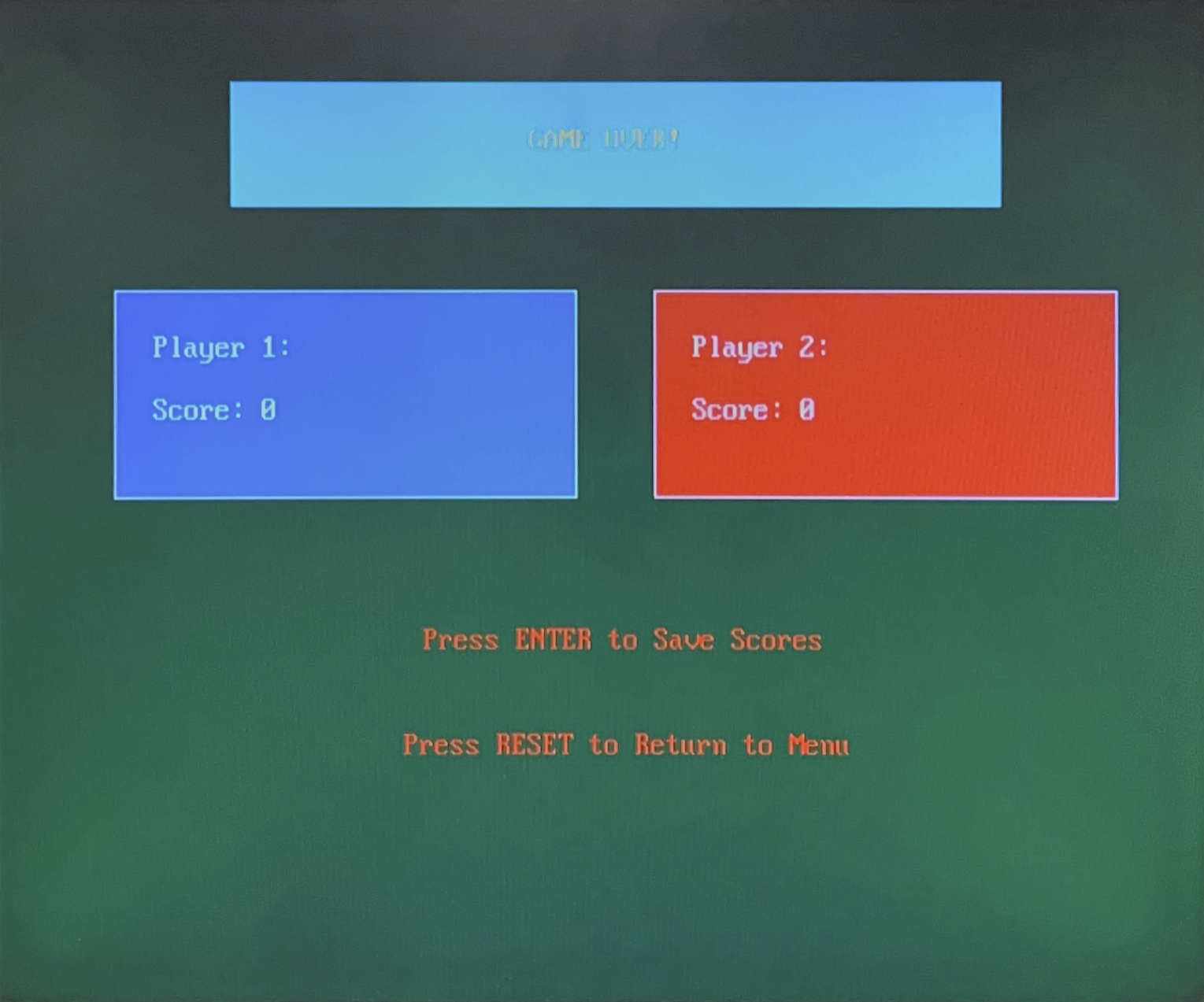
GAME_OVER screen
The leaderboard input thread within core 0 is essentially a serial listener that waits for
input.
Based on the player input, it will write a player name and score to EEPROM via I2C. This thread
waits for a semaphore signal from the input handler thread to begin. The semaphore is signaled
when
the
game is in the GAME_OVER state and the player has selected to save their score.
The timer callback ISR in core 1 is responsible for updating the game timer. It executes every
second
and
decrements the seconds_remaining variable. This variable is used to determine when
the
game
ends and the gameState changes to GAME_OVER.
Hardware Design
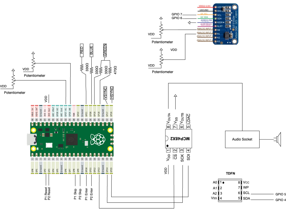
This section details the hardware design of our Game of 24 system, which brings together multiple elements to support real-time gameplay and user interaction. The Raspberry Pi Pico serves as the central controller, interfacing with external peripherals including a DAC for audio output, a VGA display for graphics, an ADS1115 ADC for reading joystick input, and an EEPROM chip for persistent leaderboard storage. A custom game controller PCB connects to the system via GPIO, providing buttons and a joystick for player input. A full schematic of the hardware setup is shown below for reference.
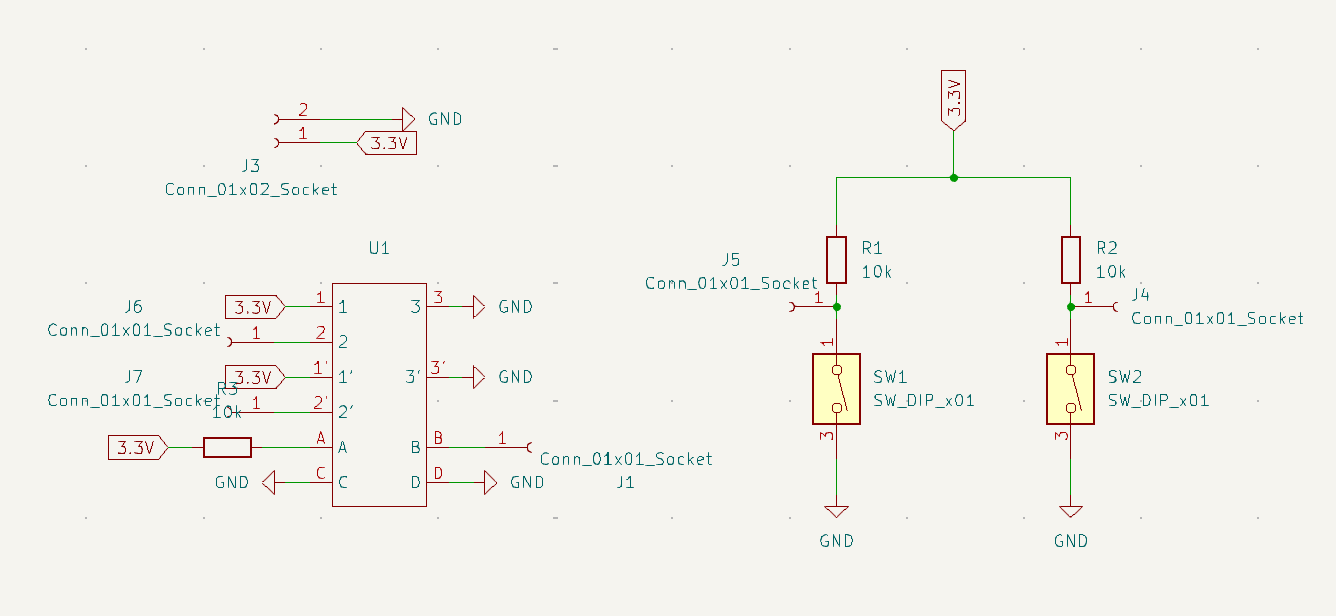
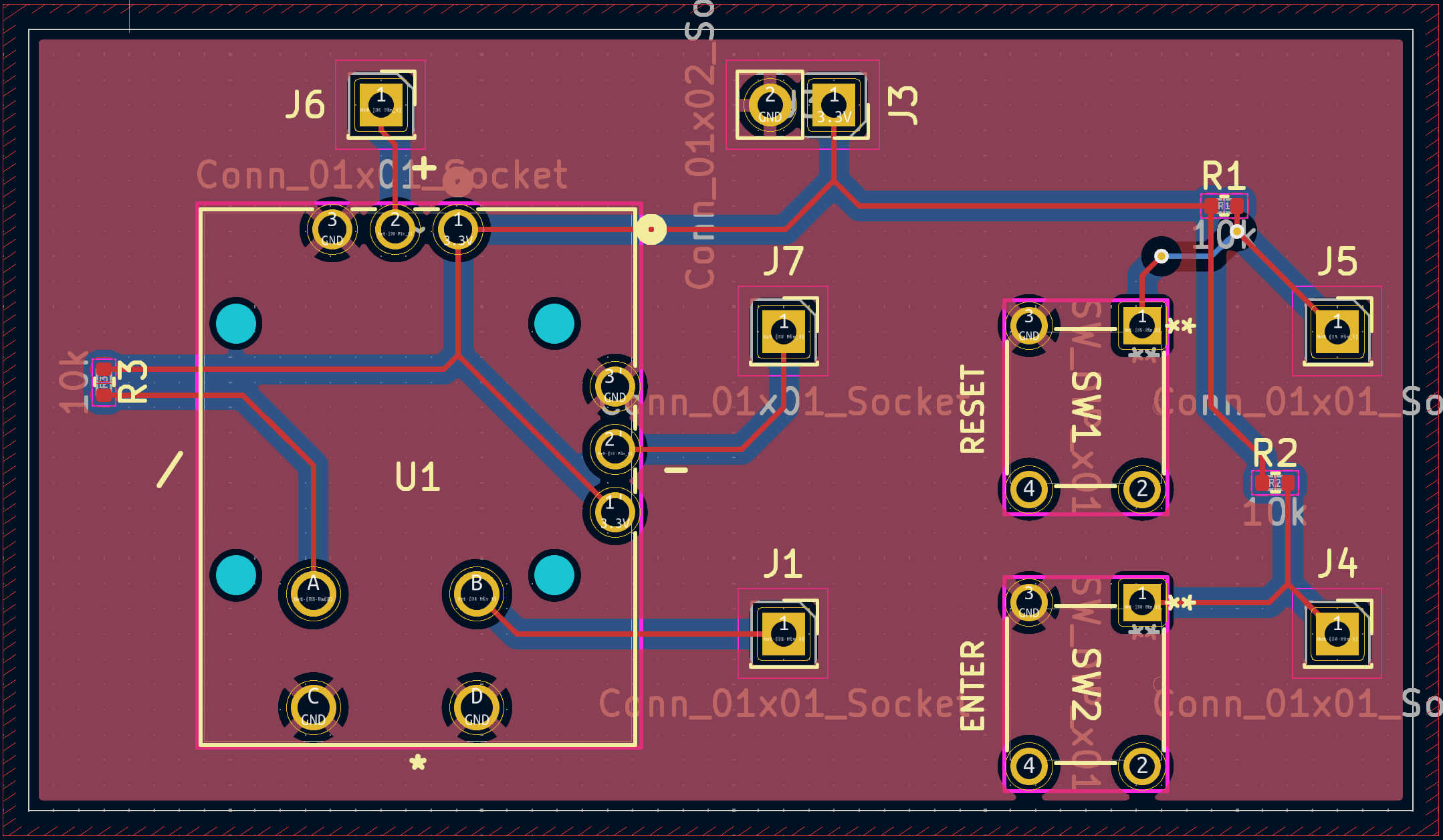
Custom Game Controller PCB Design
The custom game controller PCB includes three push buttons and a two-axis analog joystick, providing interactive input for in-game control and selection. Each push button is implemented as a Single-Pole Single-Throw (SPST) switch. One leg of the switch is connected to a Raspberry Pi Pico GPIO pin, while the other is connected to ground. A 10 kΩ pull-up resistor is connected between each GPIO pin and the 3.3 V supply, ensuring that the pin reads a logic high when the button is unpressed. When the button is pressed, the pin is pulled to ground through a low resistance path, allowing the software to detect a logic low. Transitions from high to low are used to trigger actions such as confirming a selection or cycling through menus. For Player 1, the Reset, Enter, and Skip buttons are connected to GPIO 2, GPIO 10, and GPIO 8, respectively. For Player 2, the same functions are wired to GPIO 3, GPIO 11, and GPIO 9. The custom game controller PCB schematics and layout are shown below.
Each joystick used in the game controller consists of two internal potentiometers that detect movement along the X and Y axes. Hardware wise, each potentiometer acts as a variable resistor wired as a voltage divider. One end of the potentiometer connects to 3.3 V (VDD), the other to ground (GND), and the center pin providing an output voltage that varies based on the joystick’s position. As the user tilts the joystick, the resistance between the center pin and each rail changes, resulting in a varying output voltage. This analog voltage is fed into an external ADC, which converts it into a digital value and sends it to the Raspberry Pi Pico via I2C.
In software, the joystick input is processed by a function such as joystickSelect(),
which takes in
the
digitized X and Y values and compares them to a defined center position. The function calculates the
difference (delta) between the current reading and the neutral center value. To reduce noise and
prevent
small unintentional movements from being registered, a deadzone threshold is applied. If the
joystick is
tilted far enough beyond this deadzone, the direction is determined by comparing the magnitude of
the X
and Y deviations. If the horizontal movement (delta_x) is greater than the vertical (delta_y), the
function returns UP or DOWN depending on the sign of delta_x. Otherwise, it returns LEFT or RIGHT
based
on delta_y. If the joystick remains near the center, it returns NEUTRAL, indicating no movement.
This
directional output is used in-game for actions such as selecting cards, navigating menus, or moving
between elements.
EEPROM for Persistent Leaderboards
An external EEPROM chip is used to store leaderboard data, allowing high scores and player names to remain in memory across power cycles. The EEPROM communicates with the Raspberry Pi Pico over the I2C protocol, with the SDA and SCL lines connected to GPIO pins 4 and 5, respectively. The EEPROM operates at the standard 7-bit I2C address 0x50, and write operations are followed by a short delay to allow internal memory updates to complete.
The software interface for the EEPROM includes functions for reading and writing single bytes,
16-bit integers, and fixed-length names. To manage leaderboard entries, player names and scores are
written sequentially to predefined memory addresses. Each entry consists of a name padded to a fixed
length and a 16-bit score. When a new score is inserted, the insert_score() function
checks existing
entries and shifts lower ranked scores down to make room for higher ones. This maintains a sorted
list of top scores. The EEPROM memory is divided by game mode, allowing separate leaderboards for
different difficulty levels or game types. A helper function also allows full memory erasure for
resetting all stored data.
ADS 1115 for Additional ADCs
The ADS1115 is a 16-bit external ADC used in this project to monitor joystick positions since two joysticks require four ADCs. The ADS1115 communicates with the Pico via the I2C protocol, with the SDA line connected to GPIO 6 and the SCL line connected to GPIO 7. The device operates at a default I2C address (0x48) and uses an external power supply of 3.3 V, consistent with the Pico’s power supply.
In software, the joystick input is read using the ads1115_read_single_channel()
function. This
function configures the ADS1115 to operate in single shot mode, where each read triggers a new
conversion. The CONFIG register is set with parameters including the selected input channel
(mux_bits), a ±2.048 V programmable gain amplifier setting for improved resolution, a data rate of
860 samples per second, and the comparator function disabled. After initiating the conversion and
waiting for 2 ms, the function reads the 16-bit result from the ADC’s conversion register. The raw
digital value is then scaled to a range of -4096 to +4096, which is used to interpret joystick
position in the game.
MCP4822 DAC
The MCP4822 DAC converts digital audio signals from the Raspberry Pi Pico into analog output via the SPI channel. This analog signal is then played back through a speaker connected to a 3.5 mm audio jack. The DAC is powered by the Pico’s 3.3V supply (VDD connected to 3.3VOUT, VSS to GND). SPI connections are configured as follows: MISO on GPIO 12 (not used by the DAC), Chip Select (CS) on GPIO 13, Serial Clock (SCK) on GPIO 14, and MOSI (SDI) on GPIO 15. The analog output from the DAC is connected to the speaker for audio playback.
VGA Screen
The VGA display operates at a resolution of 640 x 480 and relies on two digital synchronization signals, HSYNC and VSYNC, and three analog color channels, RED, GREEN, and BLUE. Pixel updates occur at a clock rate of 25.172 MHz. Initially, both HSYNC and VSYNC are held high while pixel data is output through the analog color signals, which range from 0 V to 0.7 V to represent varying intensities.
Each row of the display is active for 640 pixel clock cycles, followed by a horizontal blanking interval consisting of 16 cycles for the front porch, 96 for the sync pulse (when HSYNC goes low), and 48 for the back porch, all during which the analog color outputs are set to 0 V. Once complete, HSYNC returns high, and the process begins again for the next row. This repeats for 480 rows per frame. After all rows are drawn, VSYNC initiates a vertical blanking period, 10 lines of front porch, 2 lines of sync pulse (VSYNC goes low), and 33 lines of back porch, before starting a new frame.
The Raspberry Pi Pico drives these signals through the following GPIO connections: HSYNC on GPIO 16, VSYNC on GPIO 17, GREEN on GPIOs 18 (through a 470 Ω resistor) and 19 (through a 330 Ω resistor), BLUE on GPIO 20 (330 Ω), and RED on GPIO 21 (330 Ω). The VGA input has an internal 70 Ω resistor per color channel, and the series resistors form voltage dividers to ensure output voltages remain within the 0 to 0.7 V VGA standard.
Results
The final implementation of the Game of 24 was functionally complete and responsive, with smooth user interaction and correct hardware behavior. The VGA display maintained proper timing and resolution, with no visible flickering or tearing during rapid updates. Real-time drawing of numbers, selection movement, and leaderboard display were stable and free of graphical artifacts. Button presses and joystick movements were detected with minimal latency, contributing to a smooth and interactive gameplay experience.
The success of our implementation of the Game of 24 project is primarily evaluated through direct gameplay. We assessed the game based on the responsiveness of player input, the smoothness of animations, and how intuitive the game controls were. For the latter, we had independent play testers give feedback on the gameplay experience.
Due to our multi-core architecture, we ran into some issues with concurrency. In the start menu, multiple setting parameters could be highlighted and selected at once due to the start menu being modifiable by both players. We resolved this by using a mutex spinlock to ensure that only one player could modify the start menu at a time.
Our core gameplay mechanics, including player input handling, card flipping animations, and real-time score tracking, functioned as expected. Sound effects were also carefully evaluated, with all audio cues accurately synchronizing to in-game actions, contributing to the arcade-like atmosphere of the game.
We validated that we generated valid solutions of a set difficulty using an online 24 solver (see Appendix E). Each of our generated solutions was verified to be solvable with a set number of solutions that matched the difficulty level.
Safety and robustness were considered in both software and hardware. Pull-up resistors on all input lines prevented floating GPIOs, and debouncing logic helped avoid accidental multiple triggers. All analog signals (VGA and joystick) were constrained within voltage ranges safe for the Pico and external devices. Usability testing mainly by the team and friends showed that users could intuitively understand the input system and play with the game without needing technical background, proving the design's usability.
Conclusions
Our final implementation of the Game of 24 met our expectations, delivering a polished, responsive, and feature-rich experience. Beyond the core game mechanics, we successfully implemented several expansion features, including a persistent leaderboard stored in non-volatile memory, smooth animations for card sliding and flipping, and a relative scoring system that adjusts based on game difficulty. The system handled two-player input concurrently with no noticeable latency or flicker, contributing to an overall polished and arcade-like experience.
If we were to revisit this project, we would focus on further expanding the gameplay features. Some potential enhancements include a "hint" system that shakes a couple of cards or highlights a possible first move when players are stuck. We could also introduce additional sound effects, such as audio cues for successfully finding a solution or performing an operation, taking advantage of the available flash memory. Additionally, we could explore new game modes, such as a challenge mode where players compete to solve a set number of puzzles in the fastest time, offering a more diverse gameplay experience beyond the current time-based format.
As for intellectual property, we based our 24 solver algorithm on an existing open-source solution, which we modified to suit our project’s needs.
Appendicies
Appendix A
The group approves this report for inclusion on the course website.
The group approves the video for inclusion on the course youtube channel.
Appendix B: Software
The code for this project is available on GitHub here.
Appendix C: Hardware
See hardware design section for schematics.
Appendix D: Work Distribution
Ray worked on:
- Controller PCB design, layout, and assembly
- Interfacing with ADS 1115, EEPROM w/ I2C.
- Game Over, Leaderboard page design
- Python script for converting PNGs to 2D C arrays
Sean worked on:
- Designing software architecture
- VGA Driver modifications for sliding, flipping cards and pasting images
- Start Menu, Game Playing page design
- Core game logic for main gameplay loop, handling player input, handling concurrency
- Integration
Shizhe worked on:
- Converting MP3 audio files to C arrays
- Integrating sound effects into core game logic
- Controller PCB assembly
- Developed algorithm for generating card collections at a set difficulty level.
Appendix E: References
Course References
- Course Website: ece4760.github.io
- RP2040 Demos: Example Code
Datasheets & Documentation
Other References