Pii Bowling
ECE 4760 Spring 2025
Raphael Thesmar (rft38) & Kristen Moon (kjm264)
Video 1: Demonstration Video
Introduction
This project mirrors a childhood favorite game, Wii Bowling, with a microcontroller twist. Our Wii Bowling implementation utilizes two Raspberry Pi Pico W boards– one as the hand-held controller, and one connected to our VGA display. The controller-system uses an IMU to track the user’s bowling movements and has two buttons to track user inputs. IMU and user input data are sent from the controller to the VGA-system Pico with UDP communication. The Pico W and VGA system runs a bowling physics simulation with the IMU swing data and then displays the ball and pin movements through VGA graphics. We built a cohesive two-player bowling game that includes a classic bowling scoreboard, with all the bowling game logic.
This project presented a unique challenge of creating a playable and believable game, while balancing the difficulties of integrating network communication, hardware peripherals, collision physics, and VGA graphic design. We learned many new things about the game of bowling, including the sometimes complicated intricacies of bowling scores. We also developed a newfound appreciation for game design– taking care to create visuals that were both fun and satisfying to watch.
High Level Design
Pii Bowling was heavily inspired by Wii Bowling, originally designed for the Nintendo Wii. In Wii Bowling, the user can choose the ball’s trajectory angle and release point with their Wii controller. The user then presses a button to track their swing and the game takes into account any spin and their velocity from swing movements. We essentially wanted to imitate this game design but with only one sensor– an IMU. This is where our design and the Wii Bowling game design diverges– since they have an additional optical sensor that tracks where the remote is pointing and gets orientation data (useful for bowling swing trajectory tracking). With our one IMU, and a few buttons, we still mirror the choice of angle and release point, and track the spin and velocity of the bowling ball based on the user’s swing. Our graphics are more simplistic, choosing to display the game from an overhead rather than Wii Bowling’s complex animations.
No existing patents, copyrights, or trademarks were violated in the creation of this project. Although we found inspiration from Wii Bowling, our implementation and design choices diverged to result in a unique adaptation.
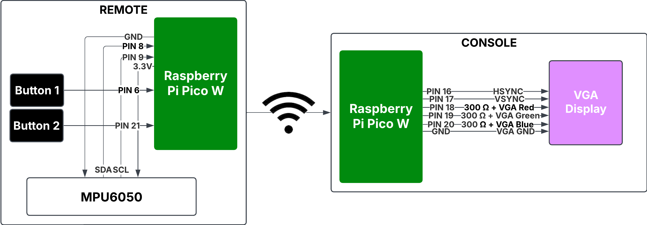
Figure 1: High-level hardware block diagram
The block diagram above shows our high-level hardware design and components. On the remote side, we had two buttons, an IMU and a RPi Pico W. We used two pins, 6 and 21, to hook up the buttons. We used the SDA and SCL connections from pins 8 and 9 to connect the IMU, MPU6050, to our Pico. Additionally, our remote controller was built to be handheld, so we added a battery pack to power the Pico, using pin 39. On the console side, we had another RPi Pico W connected to a VGA display. We used pin 16 for HSYNC, pin 17 for VSYNC, pin 18 for VGA red, pin 19 for VGA green, pin 20 for VGA blue, and hooked up ground.
Background Math
The math can be separated into (1) the motion feature extraction algorithm and the physics engine. We explain the math behind both of those below:
-
The Motion Feature Extraction (MFE):
The algorithm which we use to turn the raw IMU data which was transferred over UDP into swing data. Firstly, we pass the raw IMU data, including accelerometer and gyroscope readings in X, Y, Z direction of the MPU 6050, in a low-pass filter to smooth the data following this equation: \( x_i = \alpha x_i + (1-\alpha) x_{i-1}\), where \(\alpha=0.8\), a value we converged to after trying others and observing the most stability without the loss of valuable signal. We then assert the swing is valid, ie. contains a long enough back and forward swing by analyzing the rotational patterns in the Z-axis. Specifically, we look for a negative rotation (below -30°/s) indicating a backswing, followed by a positive rotation (above 40°/s) indicating a forward swing. We require at least 3 frames in each phase, while also checking that the total swing happens within a reasonable timeframe (0.3-3.0 seconds) and follows a natural bowling motion pattern with limited direction changes (1-5). This helps us reject random shaking or invalid movements that don't represent an actual bowling throw.
Finally, we extract the output speed and spin of the balls. We use the gyroscope data which measures the angular velocity of the IMU in degrees and convert it to linear velocity by using the following formula: \(v=r*\omega*\frac{\pi}{180}\), where \(\omega\) are the values measured by the IMU's gyroscope in degrees and \(r=0.8m\) or the average length of a human arm. Similarly to the preprocessing of the raw data, we use another high-pass filter to calculate the instantaneous changes in motion, which more accurately represents the release characteristics of the ball at the very end of the swing. For the final output, we combine both maximum values and filtered values using weighted averages (50/50 for speed and 35/65 for spin) to balance peak intensity with sustained motion, providing a more realistic representation of how a bowling ball would behave when released from the player's hand.
-
The Physics Engine:
In general, this portion of the code was responsible for updating the pins and the bowling ball position, velocity, as well as detecting collisions and appropriately dealing with them. The physics engine implements a 2D vector mathematics system to handle movement and interactions, with specialized functions for vector operations (addition, subtraction, scaling, normalization, dot products).
The simulation initializes by translating real-world motion data from the IMU sensors into the virtual environment. The ball's initial position, velocity, and spin are set based on the player's throwing motion. The ball's initial velocity is calculated using trigonometric functions where
v_x = speed * cos(θ)andv_y = speed * sin(θ), converting the player's release speed and direction angle into component velocities.For pins, the physics is more complex as it includes both positional and rotational dynamics. Each pin tracks not just position and velocity but also angle and angular velocity. The pin position updates follow the same Euler integration as the ball, but additionally, the angle updates with
angle += angular_velocity * time_delta. A pin is considered toppled when its absolute angle exceedsPIN_TOPPLE_THRESHOLD. In our case, we set that 0.1 as we found it to be the most realistic.Collision detection uses sphere-based calculations where objects collide if the distance between their centers is less than the sum of their radii. When collisions occur, the engine calculates an impulse-based response that conserves momentum while accounting for elasticity. For a ball-pin collision, a collision normal is calculated as the normalized vector from ball to pin. The impulse magnitude follows the formula:
j = -(1+e) * relative_velocity_along_normal / (1/m_ball + 1/m_pin), where e is the elasticity coefficient. This impulse then modifies both objects' velocities proportionally to the inverse of their mass:v += impulse * (1/mass).Angular momentum transfer occurs during collisions, creating the realistic pin movement patterns seen in actual bowling. When the ball strikes a pin, part of the linear momentum converts to angular momentum, causing the pin to spin. This is calculated by taking the perpendicular component of the relative velocity:
angular_impulse = dot(perpendicular_vector, relative_velocity) * 0.2.Pin-to-pin collisions follow similar momentum conservation principles but include an additional separation step to prevent pins from overlapping after collision. This separation displacement is calculated as
separation = normal * (2*pin_radius - distance) * 0.5and applied to both pins in opposite directions.The simulation also handles gutter events. When the predicted ball position for the next frame would place it beyond either the left or right gutter boundary, the physics engine intervenes with specialized handling and zeroing out the ball's y-velocity component (v_y = 0). This effectively eliminates any lateral movement. Simultaneously, it snaps the ball's position precisely to the gutter edge, setting the y-coordinate to either _left_gutter or _right_gutter depending on which side the ball is approaching from. From this point, the ball continues moving exclusively along the x-axis down the gutter, with only its x-position updating on subsequent frames (position.x += velocity.x * time_delta). Additionally, if the ball moves beyond the lane or its speed drops below a minimum threshold, the simulation is completed, allowing the game to tabulate the score. Below, we include a figure of an example swing where the ball ends up in the gutter:
Figure 2: Example Swing with Gutter Ball
The main physics loop coordinates all these calculations for each frame: updating the ball, checking ball-pin collisions, updating each pin, checking pin-pin collisions, and finally determining if the simulation should end based on the ball's position or speed. This comprehensive physics model captures the essential dynamics of real-world bowling, translating the player's physical motion into an authentic virtual bowling experience. A more realistic engine would have modeled the pins as cylinders but this was simply too complicated to implement and took too long to run. More on this in the later section.
Gameplay Mechanics
Bowling is usually played in 10 frames and two rolls per frame, with the exception of the 10-th frame, in which the user is given three frames as long as all pins are knocked down by the end of the second frame. If a user has a strike on the first frame, they will skip the second frame, letting the opponent take their turn. Our gameplay aims to follow the bowling gameplay. The two players would first be met with a welcome screen shown below in Figure 3.
Figure 3: Welcome Sreen GIF
By clicking any of the two buttons on the remote, they would then be able to move to the Pii Bowling game play. The player can then determine the initial position of the ball. The green arrow, representing the initial position of the trajectory, moves along five positions equidistant from each other along the width of the bowling alley at x=0. The user can pick the desired location by clicking on button 1 with the appropriate timing. This is demonstrated in the first second of video 2.
Video 2: Video of Sample Swing
Once the player has picked the trajectory’s initial position, they must pick the appropriate angle for the release of the ball. The green arrow is used again to represent the release angle of the swing, swinging from 90° to -90° and back. Refer to video 2 between second 1 and 3 for an illustration. The player has to click button 1 with the appropriate timing once again to pick the direction of the trajectory. In the next state, the player then needs to swing the remote, mimicking the swing of bowling, while pressing button 2. The gameplay extracts the remote speed and the spin depending on the swing, which will both impact the trajectory of the ball. Once the user releases finishes his swing and releases button 2, the console will start simultaneously simulating the trajectory, ie. the next position of the ball, pins and whether they have fallen, and animating the updates. This process continues until either the bowling ball is beyond the end of the bowling lane or if the swing is weak and the ball’s velocity falls to 0. Once the simulation and animation phase is over, the console will calculate the number of pins which were knocked down, update the score of the user, depending on whether the roll was a strike, spare or neither, and update the game tracking variables. In other words, depending on the outcome the game will switch players, if all pins are knocked down or the two rolls are over, or will allow the player to roll again, if there remains one or more pins standing and if the player is still on roll 1. The remote then needs to be switched hands, or not depending on whether the players change, and the game goes back to picking the initial position of the ball. This circular logic is described in the state diagram below:
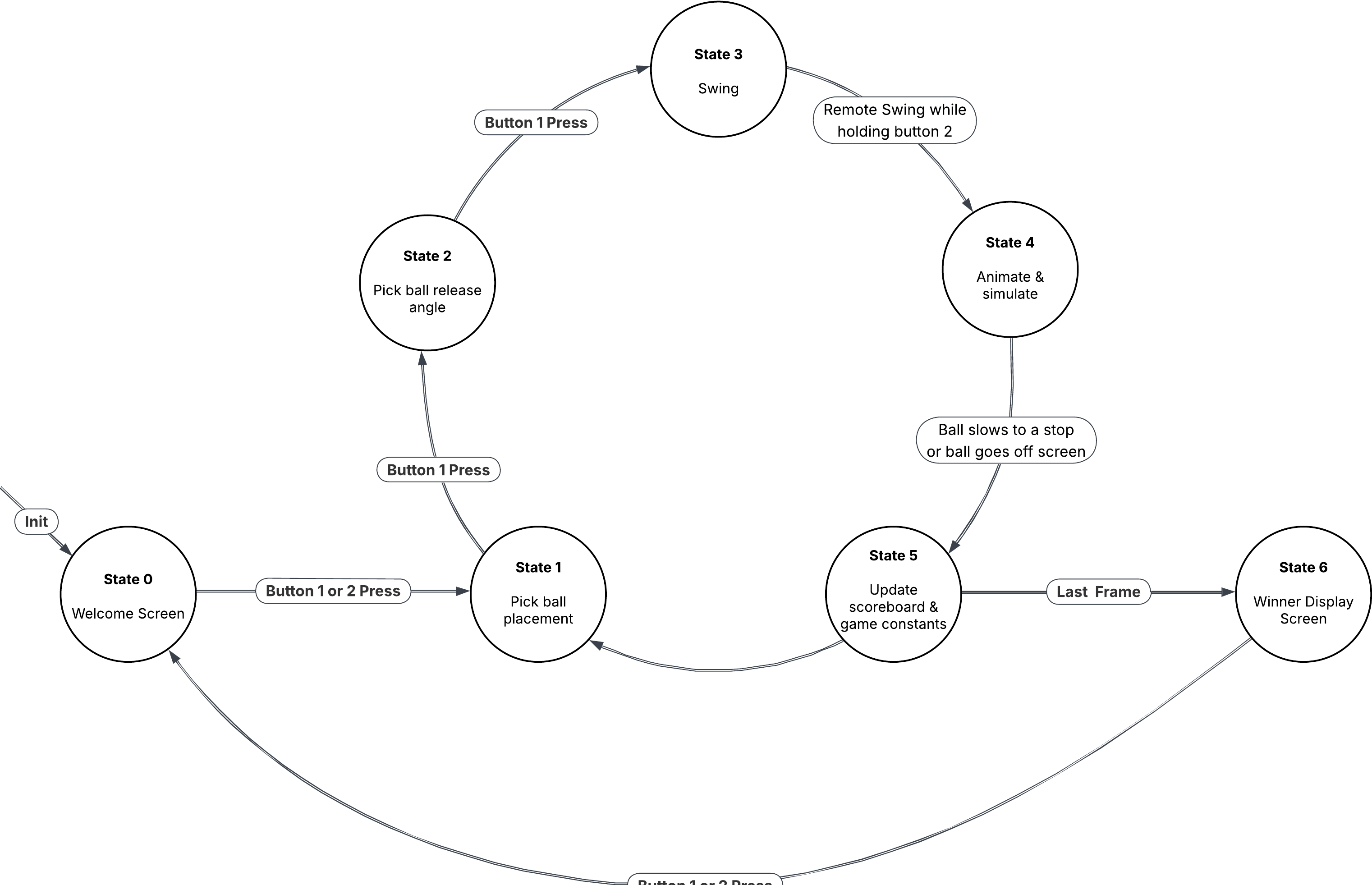
Figure 4: Pii Bowling State Diagram
If both players are done with their 10-th frame, the game will move to the winner display screen, instead of continuing to the next frame. This screen simply displays the winner of the game, player #1 or player #2. In order to exit the winning screen and return to the welcome screen, the user can either press button 1 or button 2.
Hardware/Software Trade Offs
In designing our bowling game system, we faced several critical hardware and software trade-offs that influenced the final implementation. When selecting an IMU, we balanced price against functionality. The MPU6050 offered a good compromise, providing 6-axis motion sensing (3-axis accelerometer and 3-axis gyroscope) at a reasonable cost. While more expensive IMUs might have provided higher sampling rates or additional sensors like magnetometers, the MPU6050 delivered sufficient data quality for our motion analysis needs without exceeding our budget constraints. Our motion feature extraction algorithm was designed to work effectively with this sensor's capabilities, using filtering techniques to compensate for noise and drift issues.
The choice between UDP and Bluetooth for wireless communication represented another significant trade-off. We ultimately selected UDP over Wi-Fi for its lower latency and simpler implementation. Our experiments showed that UDP's occasional packet loss had negligible impact on gameplay, as the high sampling rate of motion data meant that losing a few samples didn't significantly affect trajectory analysis. In fact, the reduced latency from using UDP instead of TCP more than compensated for any reliability concerns, resulting in responsive and natural-feeling motion controls. The simplicity of the UDP implementation also allowed us to focus more development time on game mechanics rather than communication protocols, though it did require both devices to be on the same Wi-Fi network.
For display technology, we chose VGA output for its wide compatibility and direct control capabilities. While HDMI might have offered higher resolution, the complexity of implementing an HDMI controller was prohibitive given our project timeline and resource constraints. VGA allowed us to achieve sufficient graphical quality for an engaging bowling simulation while maintaining precise timing control over the display signals. The 640x480 resolution proved adequate for rendering the bowling lane, pins, and scoreboard with appropriate detail. Our decision to implement custom graphics routines rather than using a graphics library gave us greater control over optimization, allowing us to selectively update only the changing portions of the screen.
Leveraging the Raspberry Pi Pico's dual-core architecture represented an important hardware/software trade-off that significantly improved performance. By dedicating one core exclusively to VGA signal generation and graphics rendering, we ensured smooth visual output without interruption from network processing or game logic. The second core handled network communication, input processing, and physics simulation. This division required careful synchronization between cores using volatile variables and semaphores, adding some complexity to the code. However, the performance benefits far outweighed the added development complexity, allowing us to maintain a consistent frame rate even during intensive physics calculations when multiple pins were in motion.
The interface design presented a final hardware trade-off in determining the optimal number of buttons. We settled on two buttons for the remote controller: one for initiating and executing the bowling swing, and another for UI navigation and confirmation. Adding more buttons could have allowed more direct control over gameplay elements, but would have complicated both the hardware design and user experience. Our two-button approach, combined with motion sensing, struck a balance between simplicity and functionality. The primary button captured the bowling motion when held down, while the secondary button allowed players to navigate the game interface and confirm selections. This minimal input scheme made the system more approachable for new users while still providing sufficient control for an engaging bowling experience.
Program/Hardware Design
Hardware Design
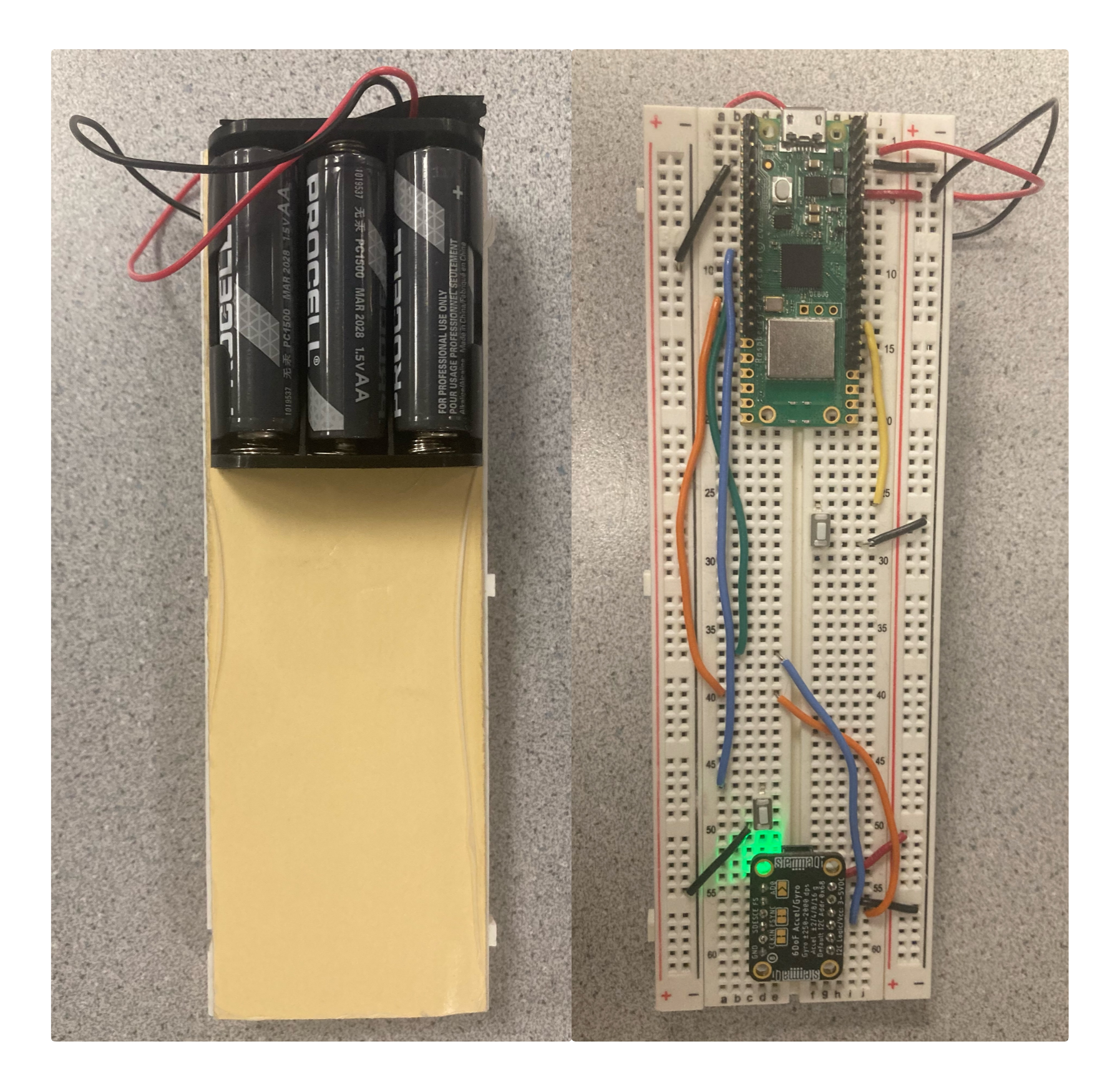
Figure 5: Physical remote setup
As mentioned previously, we used the MPU6050 IMU to get movement data of the user’s bowling swing on the remote. The MPU6050 IMU contains an accelerometer and a gyroscope, giving us two different methods to get spin and initial velocity data, but more on this in the Program section. In order to retrieve the gyroscope and accelerometer data, we made use of the I2C communication protocol. We thus connected GPIO 8, the IC20 SDA pin, to the SDA connection on the IMU, GPIO 9, the IC20 SCL, to the SCL on the IMU, the Pico 3.3V to VIN and the ground of the IMU and Pico controller. The I2C (Inter-Integrated Circuit) is a two-wire serial communication protocol designed for efficient communication between integrated circuits on the same board, where the SDA (Serial Data) line carries bidirectional data and the SCLK/SCL (Serial Clock) line provides timing synchronization, with both lines requiring pull-up resistors to maintain an idle high state.
In the MPU6050 IMU setup, the Raspberry Pi Pico (acting as the controller/master) initiates communication by sending a start condition (pulling SDA low while SCL remains high), followed by the MPU6050's 7-bit address with a read bit, then generating clock pulses on GPIO 9 (SCL) while the sensor responds by placing gyroscope and accelerometer data on GPIO 8 (SDA), with acknowledgment bits confirming successful transmission.
Two buttons are connected to the remote side Pico as user peripherals. We connected one end of the button to the ground of the Pico and the other end to pin 6. The other button connected one end to ground and the other to pin 21. The buttons then simply output 0 or 1 depending on whether it was pressed.
To power our remote controller Pico, we used a battery pack strapped to the backside of our breadboard. We used three 1.5V AA batteries in series which were then connected to pin 39 of the Pico and to the Pico’s ground. This allowed us to use the remote control without being tied to a plug in power source. Refer to figure 5 which shows the back and front of the remote set up.
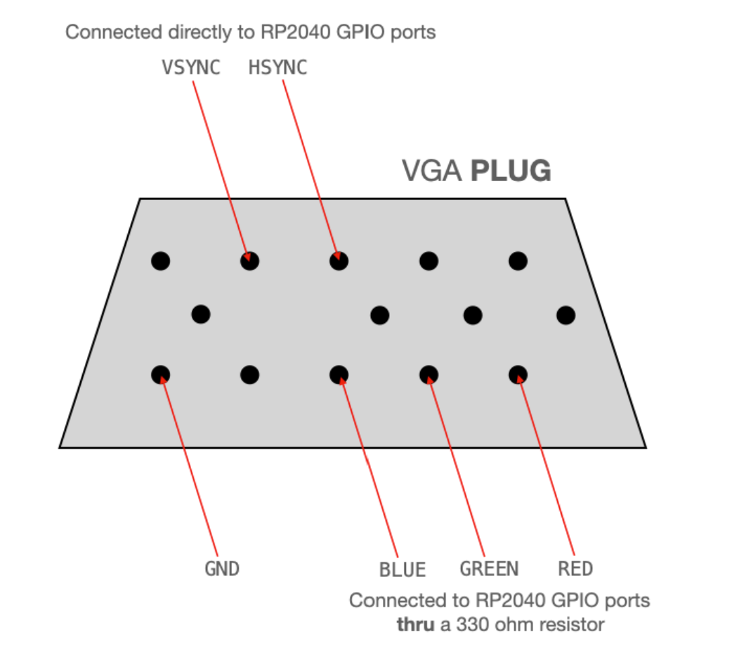
Figure 6: Specific connections to the VGA
The VGA display was used to display our bowling game logic and graphics on the console side. The VGA driver bridges the gap between the Raspberry Pi Pico (RP2040) and the screen through three synchronized PIO state machines running at 25MHz, with each handling different aspects of the VGA protocol. The first state machine generates the HSYNC signal that indicates when to start a new row of pixels, the second produces the VSYNC signal that marks the beginning of a new frame, and the third outputs the RGB color data for each pixel. These state machines are synchronized via interrupts, with the RGB machine waiting for signals from the VSYNC machine before outputting color data.
To transfer pixel data from the microcontroller to the display, the system employs two chained DMA channels; one sends color information to the PIO state machine while being paced by the state machine's FIFO emptying, and the other reconfigures and restarts the first channel to create a continuous data flow. The digital HSYNC and VSYNC signals connect directly to the VGA connector from GPIO 16 and 17 respectively, while the RGB signals pass through 330 Ω resistors to create appropriate voltage levels (0 to 0.7V) for the display through voltage division with the monitor's internal 70-ohm resistors.
Since the Pico does not have a direct VGA connection, we used female-male jumper wires to connect into the VGA connector as illustrated above. As briefly mentioned above, we connected GPIO 16 directly to VGA Hsync, GPIO 17 to VGA Vsync, GPIO 18 to a 330 Ω resistor to VGA Red, GPIO 19 to a 330 Ω resistor to VGA Green, GPIO 20 to a 330 Ω resistor to VGA Blue, and finally the RP2040 ground to the VGA ground. Below, we include a photo of our console breadboard setup:
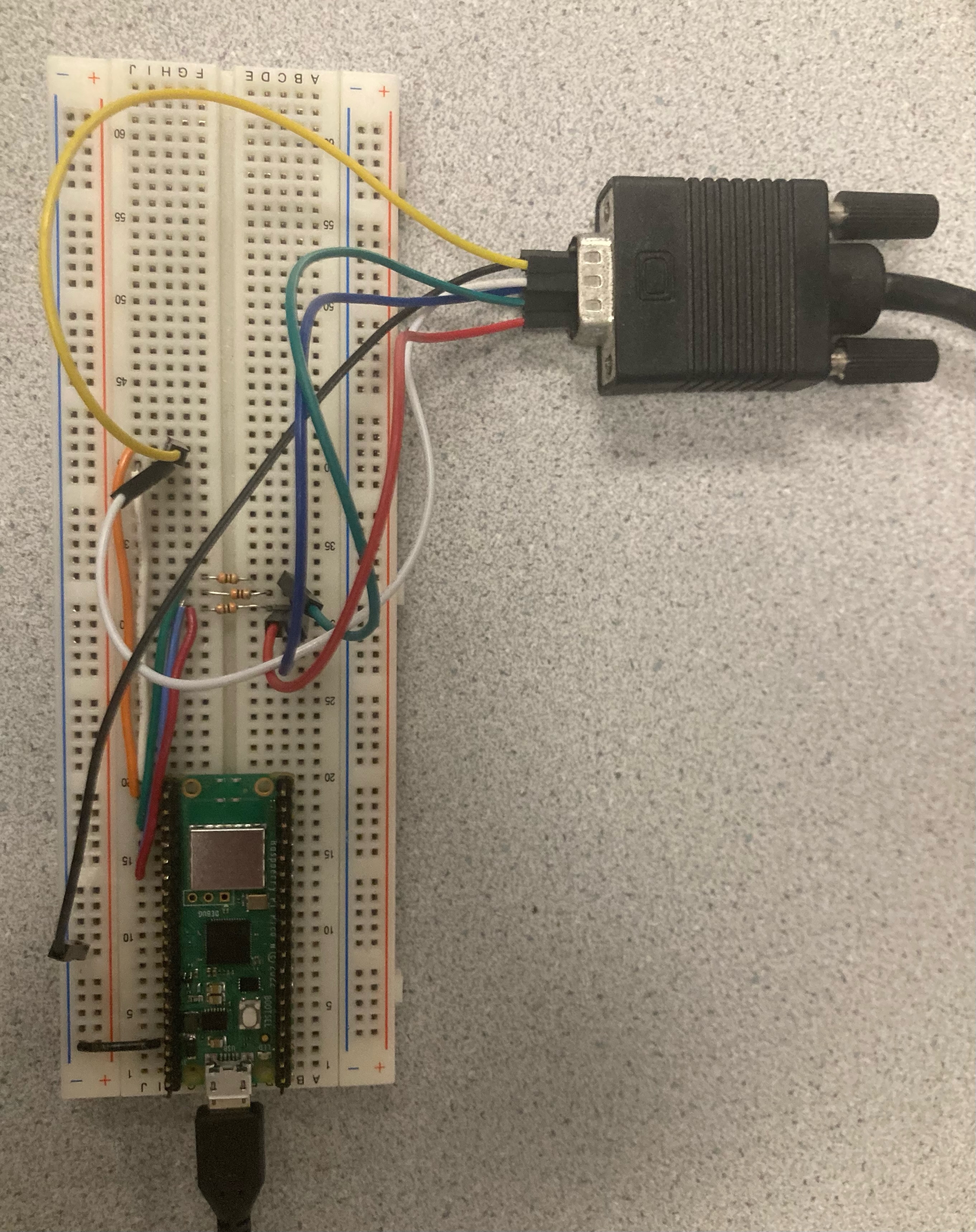
Figure 7: Console breadboard setup
Program Design
Overall the program can be split into four parts: the remote and console UDP code, the VGA display code, the motion feature extraction code, and finally the bowling physics code. While the VGA display and motion feature extraction components were not easy to code, the UDP code and the physics engine were by far the most complex and time-consuming portions of the code base. The physics simulator is not only built on many moving pieces, thus opening the way for layers of bugs, but also needs to interlock perfectly in order to work together. Additionally, the physics engine required a very long fine-tuning process, ensuring that the ball trajectory, ball-pin, and the pin-pin collisions looked authentic. The UDP process was equally challenging as it required implementing reliable transmission protocols over an inherently unreliable connection medium.
UDP
In our program, UDP serves as the communication between the remote (transmitter) and the console (receiver). We selected UDP for its low latency characteristics, which are essential for capturing and responding to real-time motion data. The protocol's minimal overhead is particularly advantageous on the resource-constrained Raspberry Pi Pico W microcontrollers, allowing for efficient wireless communication without unnecessary protocol complexity.
The implementation consists of two main components: a transmitter (remote) and a receiver (console). On the transmitter side, we utilize the lwIP stack's UDP functions to create a Protocol Control Block that targets the receiver's IP address on port 1234. When a player presses the main button, the controller continuously reads acceleration and gyroscope data from the MPU6050 sensor, packages this data into fixed-size datagrams, and transmits them to the game emulator. Each packet contains six motion values (three acceleration axes and three rotation axes) plus a timestamp, all represented as fixed-point values for consistent interpretation across devices.
We implemented a packet allocation system using the pbuf_alloc() function to create appropriately sized buffers for our data. After populating these buffers, we transmit them using udp_sendto(), providing the destination address and port number. Our code includes error handling to detect and report transmission failures, though in practice, the local wireless connection proves quite reliable.
A key part of our implementation is the use of special values to signal specific events. When the player releases the button, indicating the end of a bowling swing, the controller sends a packet with all fields set to -1. Similarly, when the confirmation button is pressed, it sends a packet with all fields set to -2. These special values act as control signals that trigger state changes in the game without requiring separate communication channels or protocols.
The callback function runs in an interrupt service routine context, where it quickly copies the payload data to a buffer and signals a semaphore to notify the main application thread. This asynchronous approach prevents network processing from blocking the game's rendering and physics simulation, ensuring smooth gameplay even while continuously receiving sensor updates.
Our main processing thread waits on the semaphore and interprets the received data according to its content. Normal motion values are added to a buffer for feature extraction, which ultimately determines the trajectory and speed of the virtual bowling ball. Special values (-1 and -2) trigger game state changes, such as confirming the player's position, locking in the throwing direction, or executing the physics simulation after a completed swing.
On the receiver side, the game emulator binds to port 1234 and registers a callback function to process incoming UDP packets:
Our receiver and transmitter code comes both from Bruce’s resource– “UDP data array from Picow to Picow”. And additionally combined some code from Prof. Adams UDP demo code.
Remote Program
The remote program, which runs and collects all user inputs, consists of only a few components. The main being UDP, which has been described in the previous section. The remote program used the button inputs to control the UDP outputs. We programmed the buttons, with state variables, to allow different data to be packaged and transmitted to the console. When the main button is pressed– the console program transmits IMU data. When the secondary button is pressed– it transmits an array full of -2.
As previously mentioned, whenever the main button is pressed, the remote program gets IMU data. The communication between the Pico and the IMU is established through the I2C protocol, which requires two signal lines: SDA (data) on GPIO 8 and SCL (clock) on GPIO 9. In our software implementation, the I2C interface is first initialized with a specified baud rate using i2c_init(I2C_CHAN, I2C_BAUD_RATE), followed by configuring the appropriate GPIO pins for I2C functionality with the gpio_set_function() calls. Internal pull-up resistors are enabled on both SDA and SCL pins through the gpio_pull_up() function, ensuring proper signal integrity. The MPU6050 is then reset and initialized using the mpu6050_reset() function, which configures the sensor's internal registers for proper operation.
Data acquisition is performed in the interrupt service routine (on_pwm_wrap()), where the mpu6050_read_raw() function retrieves raw accelerometer and gyroscope measurements in 15.16 fixed-point format. These measurements are stored in the acceleration and gyro arrays, which can then be converted to floating-point values using the fix2float15() function for further processing in the PID control algorithm.
This I2C communication framework enables reliable, high-frequency sampling of the IMU data, which is critical for accurate movement data of the bowling swing. We utilized the IMU demo code for reference when designing this software implementation.
Console Program
The console program, which runs and computes all the gameplay, consists of five main components working together: the IMU Buffer which stores motion data received through UDP, the Motion Feature Extraction (MFE) translates this data into bowling parameters, the Physics Simulation calculates ball and pin movements, the Scoreboard tracks player progress, and the VGA Graphics renders everything on screen. The system uses UDP for communication between the remote controller and console, and splits processing across the Pico's dual cores for better performance.
IMU Buffer
The IMU Buffer stores and manages motion sensor data from the MPU6050 accelerometer and gyroscope.It's implemented as a dynamic data structure that expands as needed during motion capture. Each entry contains:
typedef struct {
    float ax, ay, az; // Acceleration values
    float gx, gy, gz; // Gyroscope values
    uint32_t timestamp;
} IMU_Data;
When the remote program sends swing data, and the console is in a gamestate ready to receive, the system captures the motion data and adds it to the buffer. And after each throw, the buffer is cleared with IMU_Buffer_Clear() to prepare for the next attempt.
MFE
The Motion Feature Extraction (MFE) module analyzes sensor data (a full IMU buffer) to determine bowling throw characteristics. When a throw is completed (button release), the system processes the collected data. The processing function filters the sensor noise, calculates release speed, determines spin rate, and sets trajectory parameters. These values are used to determine the path of the ball.
Physics Simulation
The physics simulation uses the MFE trajectory C structure to compute the ball movement and pin collisions in a precise, frame-by-frame update sequence. Each simulation frame follows a strict order of operations: first updating the ball's position and velocity (update_ball), then detecting and resolving ball-pin collisions, followed by updating each pin's position and state, and finally checking for pin-pin collisions. This sequence, implemented in the bowling_physics_update function, runs within a tightly controlled timing loop that maintains consistent frame rates using sleep functions to compensate for processing time variations.
The simulation continues until termination conditions are met—either the ball reaches the end of the lane or its speed drops below a threshold, at which point simulation_complete is set to true. One significant challenge we faced was pin modeling. Initially, we attempted to model pins as cylinders for greater physical accuracy, but this introduced computational complexity and collision detection challenges that undermined performance. We ultimately settled on spherical pin collision models as a compromise between physical accuracy and computational efficiency. Given more development time, we would have refined the pin physics to use true cylindrical models with proper rotational inertia tensors and more sophisticated collision detection algorithms, which would have yielded more realistic pin action, especially during complex collision chains.
Scoreboard
The scoring system follows standard bowling rules using this structure:
typedef struct {
  BowlingFrame frames[10];
  int current_frame;
  int current_roll;
  int total_score;
  bool game_complete;
  char player_name[20];
  // Statistics
  int strike_count, spare_count, gutter_count, open_frame_count;
  int best_frame_score;
  int best_frame_index;
} BowlingScore;
After each throw, recordRoll() updates the current frame and roll, and calculateScore() computes the score according to bowling rules described in the Gameplay Mechanics section. We then update the displayed score on the VGA by calling the displayScoreboard().
VGA Graphics
Our console program uses the microcontroller’s multiple cores to keep graphics running while keeping up with all the other tasks of our program. Core 0 handles UDP networking, processing input data, and game logic. Core 1 handles the VGA graphics.
This parallelism in our console code allowed us to program decent graphics to keep up with simulation details. We packaged our graphics into multiple functions, some for whole pages like the welcome screen, and some for simply updating the ball’s location as it moved down the screen. We took the time to code details such as pins with stripes, and a scoreboard view like you might see at a bowling alley.
Results
We used no concurrency in the remote controller and never observed timing issues on that side of the project. However, we did implement concurrency in the console using the Raspberry Pi Pico's dual-core capabilities. Core 0 handled networking, input processing, and game logic, while Core 1 was dedicated to VGA graphics rendering. This separation of concerns proved critical for maintaining responsive gameplay. The UDP connection was almost instantaneous between the remote and the console, with clicking a button on the remote showing immediate feedback on the console when the lab room was mostly empty. We chose the RedRover WiFi network, which performed well under normal conditions but became laggy when Phillips 238 would fill with students.
Every animation on the VGA screen was optimized to only erase what was necessary, allowing us to maintain our target of 33 frames per second with few exceptions. The welcome screen includes an animation of a stickman swinging a bowling ball and a pin falling, where only the man's arm, ball, and pin are erased and redrawn at their new locations while the rest of the screen remains static. Similarly, for the gameplay screen, we only draw the scoreboard and inactive bowling lanes once. During gameplay, only the ball and affected pins are erased and redrawn. Pins are only updated if the ball or another pin is within collision distance or if the pin is moving. Despite these optimizations, we occasionally experienced some screen flicker during complex physics interactions when many pins were in motion simultaneously.
Our motion analysis system demonstrated good accuracy in translating physical motions into game parameters. The accelerometer and gyroscope readings were processed through a low-pass filter to reduce noise, and our feature extraction algorithm reliably identified key characteristics of bowling throws. The physics simulation implemented realistic ball trajectory and pin interactions, modeling ball momentum based on swing velocity, spin effects causing curved trajectories, elastic collisions between ball and pins, pin-to-pin interactions, and friction effects as the ball rolls down the lane. The scoring system accurately implemented standard bowling rules, including proper handling of strikes, spares, and special rules for the 10th frame.
We enforced timing safety by maintaining a frame rate of 30 FPS in the console, with logic to measure frame processing time and sleep for the remaining duration if processing completed early. Diagnostic print statements would trigger only if timing requirements weren't met, helping us identify and address performance bottlenecks. Our IMU buffer implemented dynamic memory allocation with proper bounds checking to prevent buffer overflows, and network communication included error detection and reporting to ensure reliable data transfer. We also implemented button debouncing to prevent unintended double-activations when players pressed buttons on the remote controller.
The system was designed with usability as a priority, featuring simple controls with just two buttons - one for initiating and executing the bowling swing, and another for UI navigation and confirmation. The game guided players through a logical sequence from the welcome screen to position selection, direction selection, and finally motion-based bowling with the remote. Real-time visual feedback was provided for all user actions, and the comprehensive scoreboard clearly displayed frame-by-frame progress using standard bowling notation. When tested with lab peers, most users could quickly understand the control system and successfully complete bowling turns without extensive instruction. The motion-based controls provided an engaging physical dimension to the game that traditional button-based controls would lack.
Conclusion
In our final project proposal, we aimed to create a faithful recreation of the Wii bowling experience, with the remote swing fully controlling the direction, spin, and speed of the bowling ball's trajectory. While we successfully implemented the spin and speed extraction from the MPU6050 sensor, we discovered limitations in our sensor choice that prevented us from determining throw direction directly from the swing motion. A more advanced IMU with magnetometer capabilities, such as the MPU9250 or BNO055, would have allowed for absolute orientation tracking necessary for direction extraction. Instead, we adapted our design to include a timing-based direction selection, where players use button presses to determine the starting position and trajectory angle before executing their swing.
Looking ahead, several improvements could enhance our implementation. The most straightforward enhancement would be to refine our control scheme to better integrate motion and button inputs. Rather than using separate button presses for direction selection, we could detect the initial orientation of the controller during swing startup to set direction, creating a more intuitive experience that more closely mimics real bowling. This approach would maintain our existing hardware while improving the user experience. A more substantial upgrade would involve replacing the MPU6050 with a 9-axis IMU to enable complete motion tracking similar to the original Wii Remote.
Our display technology choice also presented limitations. The VGA display's 16-color palette and refresh rate constraints resulted in occasional visual flickering during complex physics interactions. A more modern display interface such as HDMI would offer superior color depth and refresh rates, allowing for smoother animations during pin collisions and more visually appealing graphics. However, this would require significant changes to our display driver implementation and potentially more powerful microcontrollers to handle the increased processing demands.
We also considered adding physical feedback elements to enhance immersion. While servo motors might have limited utility in this application, adding haptic feedback through vibration motors could provide physical responses when the ball strikes pins. Audio feedback through a simple sound system would further enhance the experience with realistic bowling alley sounds. These additions would create a more complete sensory experience without requiring substantial architectural changes to our existing implementation.
Our design adheres to applicable standards in several ways. The UDP implementation follows standard network protocols, ensuring compatibility with common WiFi networks. Our VGA signal generation conforms to standard timing specifications, enabling compatibility with standard VGA monitors. The motion sensing implementation uses the I2C protocol according to standard specifications for communicating with the MPU6050. Finally, our code structure follows modular programming practices, with clear separation of concerns between different system components, making the system maintainable and extensible for future development.
Overall, while we didn't achieve our most ambitious goal of creating an exact Wii bowling replica, we successfully developed a functional and engaging motion-controlled bowling game that demonstrates effective integration of wireless communication, sensor processing, physical simulation, and graphics rendering on resource-constrained microcontrollers.
Appendicies
Appendix A: Permissions
The group approves this report for inclusion on the course website.
The group approves the video for inclusion on the course youtube channel.
Appendix B: Code
The full project source code is available on our
GitHub repository
. It includes the header and C files which we coded: bowling_physics.c, bowling_physics.h, bowling_graphics.c, bowling_graphics.h,
bowling_score.c, bowling_score.h, connect.h, emulator_udp.c, imu_container.c, imu_container.h, mfe_algorithm.c, mfe_algorithm.h,
and remote_udp.c. It also includes file which we obtained from the course, like font_rom.h, font_rom_brl4.h, glcdfont.c,
hsync.pio, vsync.pio, rgb.pio, lwipopts.h, mpu6050.c, mpu6050.h, pt_cornell_rp2040_v1_1_2.h and pt_cornell_rp2040_v1_3.h.
Additionally, we also include some of Prof. Bruce Land's
UDP communication code , specifically the udpecho_raw.h and picow_udp_send_recv_data.c files.
Finally, there are also the pico_sdk_import.cmake and CMakeLists.txt files which we used to compile the project and slightly edited.
Appendix C: Materials
All the materical which we used were provided by the course, free of charge. We made use of 2 Raspberry Pico Ws with breadboards, 1 battery pack, 3 AA batteries, 1 MPU 6050, 2 buttons, 3 300 Ohm resistors, 1 VGA cable and display as well as many connecting wires.
Appendix D: Work Distribution
Raphael worked on the physics engine, the motion feature extraction algorithm, the VGA graphics and the overall console/remote code.
Kristen worked on the soldering of the pins to the Pico W and the other various hardware connections. She also implemented the UDP code to work with IMU, some of the VGA graphics code, part of the motion feature extraction algorithm, and the scoring system.
The work was overall split evenly between the groupmates and both worked on the report/final website.
Appendix E: References & Datasheets
- Prof. Bruce Land's UDP data array from PicoW to PicoW code
- Prof. Hunter Adam's UDP Transmitter code on GitHub
- Raspberry Pi Pico W
- MPU6050 IMU
- Protothread library
- VGA display library