Automatic Music Stand
Fall 2025 ECE4760 Final Project By Kotey Ashie (kaa86), Lina Hao(lh657)
Project Introduction
Our project is a hands-free, automatic music stand that turns pages in response to user motion.
The user wears a motion-detecting band on their arm or leg, and when they move, the stand detects the signal and automatically turns the page. This system allows musicians to turn pages hands-free, minimizing performance interruptions.
High-Level Design
Our main rationale for choosing this project is because turning music pages while playing an instrument is inconvenient and disruptive. Musicians often need to pause mid-performance to flip pages or rely on someone else to do it for them. To address this, we envisioned a music stand that detects simple arm or leg movements and automatically turns the page, allowing for smoother performances.
Hardware Design
Electrical Components
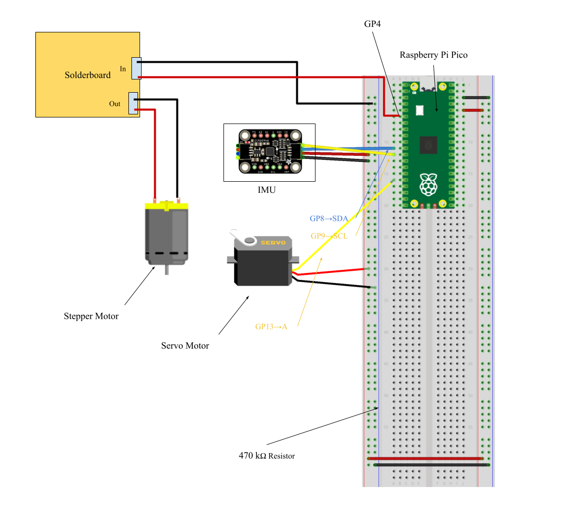
Figures 1 and 2: Hardware Setup Breadboard
Microcontroller
All system control is performed by the RP2040 microcontroller. It manages real-time angle estimation, motor control through a PID algorithm, and user interaction via a UART serial interface and push button. The RP2040 receives raw accelerometer and gyroscope data from the ICM-20948 IMU over I2C, and it processes this data through a complementary filter to estimate the helicopter arm’s angle.
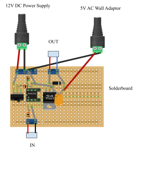
Motor Driver Circuit
A custom motor driver circuit was assembled on a solderboard to ensure reliable high-current handling. The circuit uses a 4N35 optoisolator to provide electrical isolation between the RP2040 and the power electronics. The circuit includes a logic-level N-channel MOSFET, a 1N4001 diode placed in parallel with the motor, and a 0.1µF capacitor. The motor is powered by a dedicated 5 V supply. A 12 V DC supply is used to drive the gate of the N-channel MOSFET. SPST kill switch is placed in series with the motor power to allow emergency shutdowns during testing.
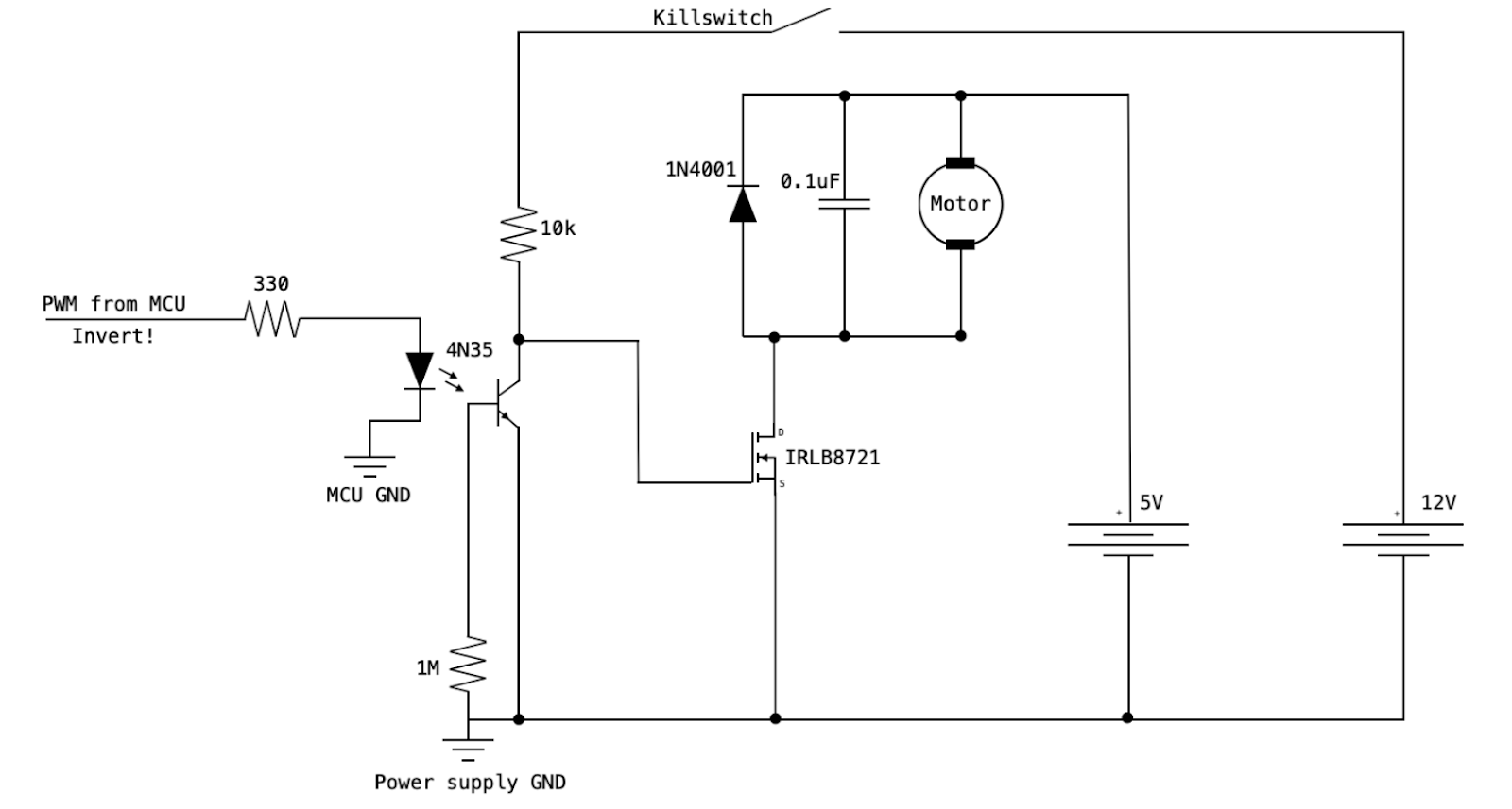
Figure 3: Motor Driver Circuit Schematic
IMU (Inertial Measurement Unit)
The ICM-20948 IMU provides 3-axis accelerometer and gyroscope data. It is connected to the RP2040 via the I2C interface and powered from the 3.3V rail. The IMU is mounted close to the rotating arm to accurately measure its angular displacement. The onboard gyroscope is used to track angular velocity, while the accelerometer provides a reference for angle, especially at rest. A complementary filter fuses the two signals to generate a stable and responsive angle estimate.
Stepper Motor
The stepper motor is employed in the system where high torque and precise incremental rotation are required. It is driven by the stepper motor driver circuit. The RP2040 outputs step pulses at a controlled frequency to dictate motor speed and position.
Servo Motor
A standard hobby servo motor is used for tasks requiring precise angular positioning over a limited range. The servo is controlled using a PWM signal generated by one of the RP2040’s GPIO pins.
Page Turning Mechanism
Original Design
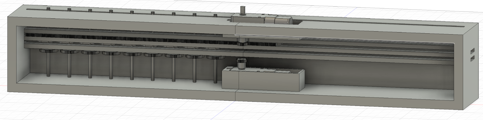
The original design for page turning operates as follows: Cut hex keys would be positioned vertically, each held within slots in a rack. Paper clips would be attached to the tops of each of the hex keys in order to hold the pages for turning. This rack would be driven by a top-mounted motor. Upon receiving a signal from the IMU, the motor would rotate the pinion, shifting the rack horizontally and aligning the next hex key into a central position. Once aligned, a bottom motor would rotate the selected hex key using a gear attached directly to it, initiating the page-turning motion. This setup supports forward and backward turning of up to 11 pages of sheet music and is compatible with sheet music in books, binders, or as loose pages.
Backup Design
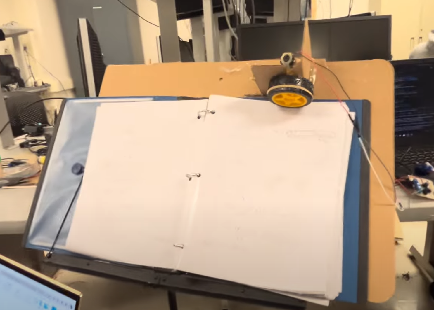
Due to time constraints, we were unable to 3D print our original design and instead implemented a backup mechanism. This alternative setup uses a cardboard sheet as the base, with another sheet setup in a right angle perpendicular to the base. Perpendicular sheet includes a slot to hold a motor with an attached wheel, positioned next to a servo motor with a popsicle stick arm. When the system is placed on a stand with sheet music, either in a book, binder, resting on the cardboard base, the wheel Moves through the slot due to gravity to the top most page of sheep music. Upon receiving a signal from the IMU, the wheel spins just long enough to lift the page, after which the servo motor completes the flipping of the page using the attached popsicle stick. This setup supports forward turning only and but could be used for far more pages.
Program Design
Our program adapts code from the ECE 4760 PID control lab to control two motors using PWM on the RP2040 microcontroller. Motion detection is implemented using an MPU6050 IMU, and when a quick movement is detected from the user, the motors are activated to simulate a page turn.The system uses an interrupt service routine on_pwm_wrap and a protothread protothread_motor to coordinate motor control and timing.
Two global boolean flags are used for synchronization as well: motion_detected is set to true when motion is detected, and wait_ended ensures that motion detection is only allowed again after a two-second cooldown period.
Interrupt Service Routine
The on_pwm_wrap function is called on every PWM cycle wrap, and it serves as the main interrupt service routine (ISR) for motion detection.
The ISR starts by clearing the interrupt flags for both motors using pwm_clear_irq, ensuring that the interrupt system is properly reset and ready for the next event. Then, it reads in raw accelerometer and gyroscope measurements from the MPU6050 IMU using mpu6050_read_raw, and these measurements are stored in the acceleration and gyro arrays respectively. The program then checks whether the detected y-axis acceleration is greater than 1.0g, indicating that the user has made a quick motion, and whether wait_ended is true, indicating that the wait period is over.
If the conditions above are met, then the program sets a PWM duty cycle to both motors using pwm_set_chan_level, and the onboard LED is turned on as a visual indicator. The motion_detected and wait_ended flags are set to true and false respectively to signal the motor thread and begin the cooldown period. While the PWM output to the DC motor works as intended, we were not able to successfully spin the servo motor using our current configuration.
Motor Control Thread
The protothread_motor thread manages motor timing behavior. It waits until the motion_detected flag is true, and once triggered it waits for 0.2 seconds, allowing the motors to run briefly and simulate a page turn. After this, the duty cycle for both motors is set to 0 to prevent the motors from spinning, the LED is reset, and motion_detected is set back to false. The thread then waits for an additional two more seconds to enforce a cooldown period on motion detection. After the wait, the wait_ended flag is set to true and the thread resumes waiting for the next motion event.
Main Function
In the main function, essential peripherals are initialized, including LED initialization, MPU6050 initialization, I2C configuration, and PWM configuration. The on_pwm_wrap ISR is also linked to the PWM interrupt and enabled. Then, the motor control thread is added to the scheduler on core 0.
Results of the Design
With our implementation, we were able to get the stand to roll up the next page when a motion was detected through the band. However, due to a last-minute switch into our backup design, we were unable to get the stand to fully turn the page automatically. Regarding safety, we ensured that the motors would be held in place during operation and utilized a motor driver circuit to safely manage high current.
Conclusions
Overall, our results did not fully meet our initial expectations, but we successfully implemented the mechanism for rolling up a page before it is turned. If we had more time, we would have looked into implementing the music stand with our original design rather than the backup design.
Appendix A
The group approves this report for inclusion on the course website. The group approves the video for inclusion on the course youtube channel.
Appendix B
For work distribution, Kotey worked on the hardware portions of the project, and Lina worked on the software portions of the project.
Code:
imu.c mpu6050.cAppendix C
References:
Hunter Adams's ECE 4760 Demo Code and LabsRP2040 Datasheet