ASL Interpreter
ECE 5730 Final Project
By Shi Gu (sg2562), Lulu Htutt (lh543), and Sana Chawla (sc2347).
Demonstration Video
Introduction
For our final project we designed and developed a glove based system that can detect the alphabets of the American Sign Language (ASL) using flex sensors and an IMU. We created this system to provide an affordable alternative to expensive commercial sign language translation systems, making communication more accessible for individuals who are non-verbal, hard of hearing, or deaf. The project uses a Raspberry Pi Pico to process sensor data from five flex sensors (one for each finger), contact sensors and an MPU6050 IMU to detect hand orientation, implementing threshold-based signal processing to detect the ASL alphabet.
High Level Design
Rationale and Sources
We chose a glove‐based ASL interpreter because wearable sensors offer a low‐cost alternative to camera-based vision systems - no special lighting, no privacy concerns, and no heavy image processing. Flex sensors directly measure finger bends and an IMU captures hand orientation, allowing real-time alphabet detection on a lightweight microcontroller. This approach makes translation accessible to users in any environment, including those with limited internet or compute resources.
We found a couple of projects in the past years of this class that were similar to our idea, and we referenced them when we ran into blocks.
Hardware Design
Our hardware includes a glove with 3 different kinds of sensors for detecting gestures of each letter in ASL alphabet. The following is the picture of our final project:
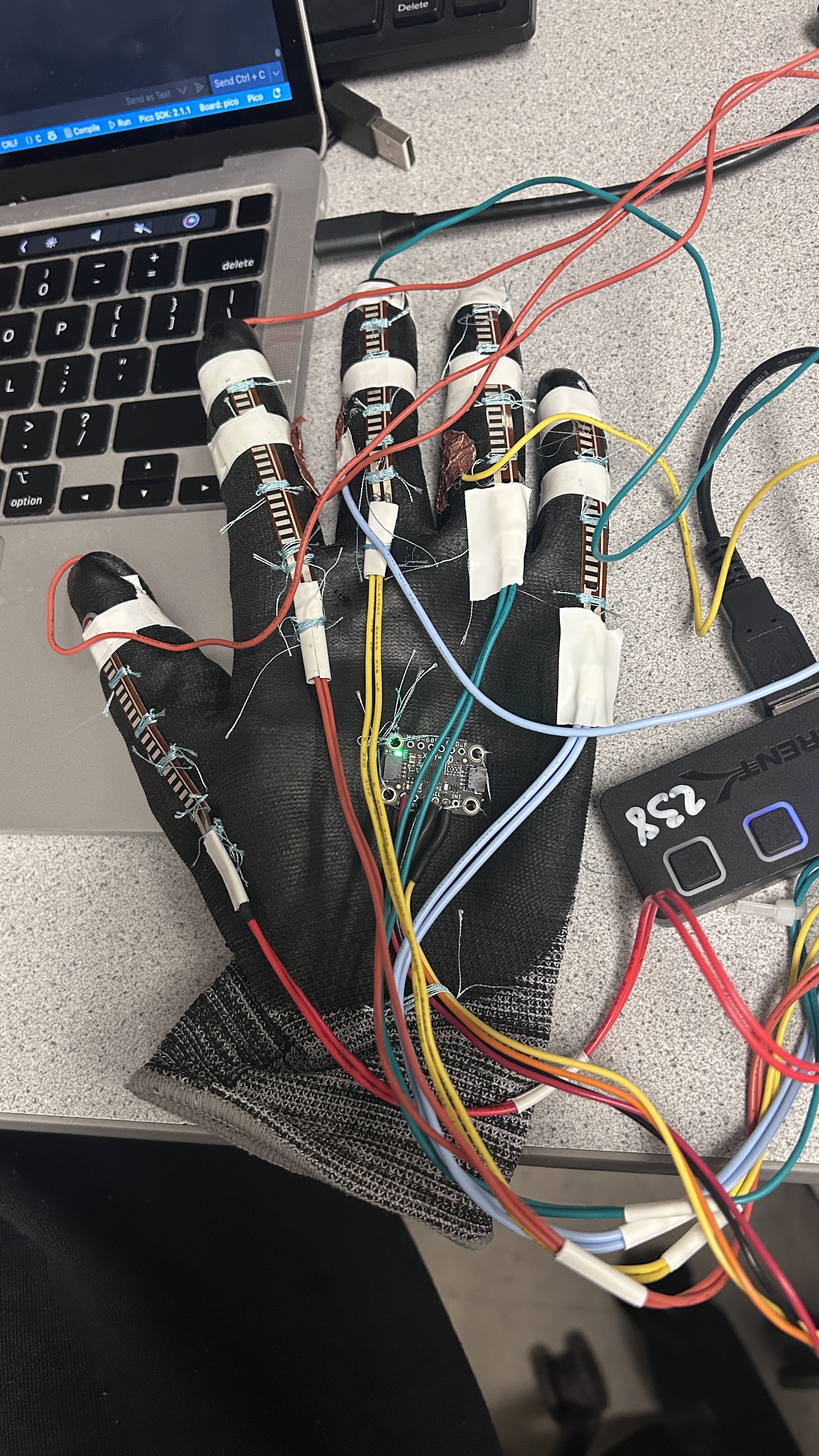
Picture of the final project
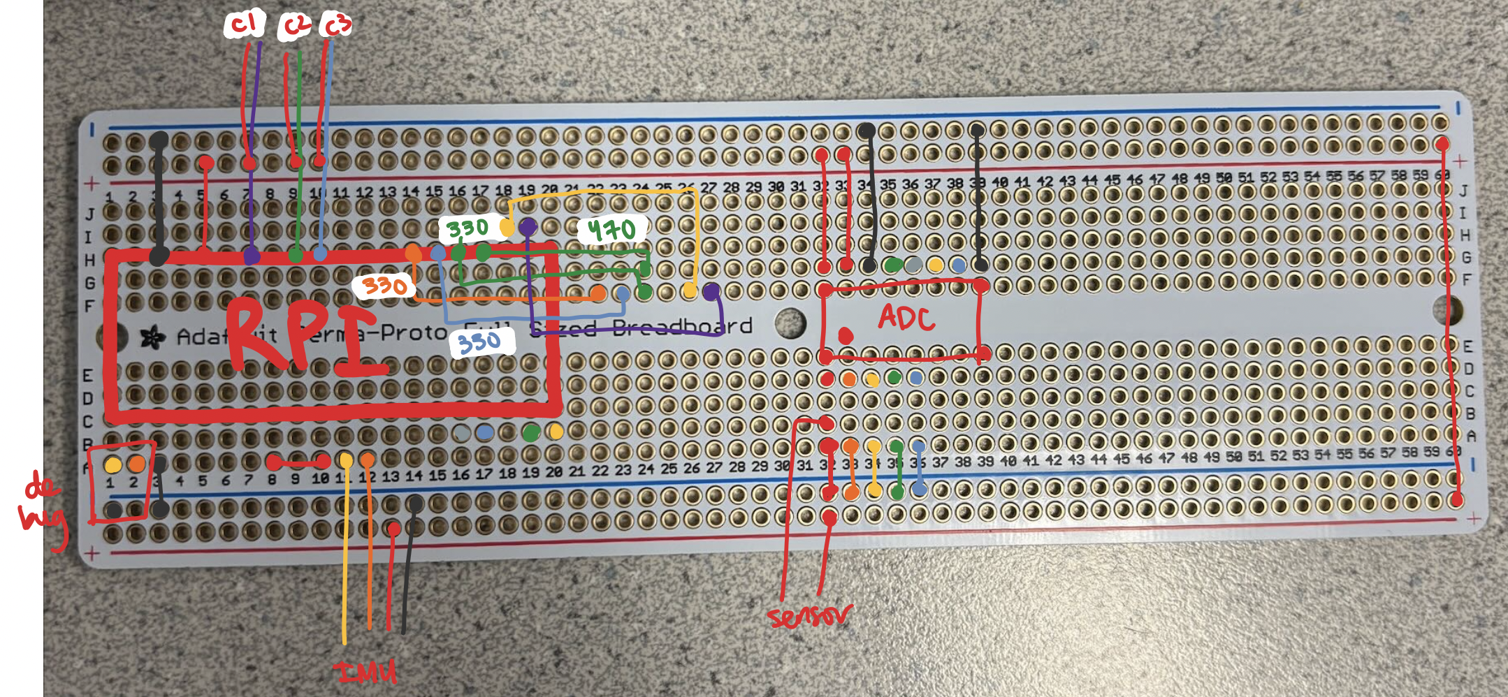
Circuit Diagram of ASL Interpreter
We placed five flex sensors on the top of each finger to detect individual finger bending. The resistance of a flex sensor increases when it is bent, allowing it to act as a variable resistor. By connecting each sensor in a voltage divider configuration with a pull-down resistor, we can convert the resistance change into a measurable voltage. The output voltage is then read by the microcontroller to determine the degree of bending. To maximize sensitivity, we selected the pull-down resistor values based on the unbent resistance of each flex sensor. One sensor had a much higher baseline resistance (~90 kΩ), while the others measured closer to ~60 kΩ. We chose resistor values that are comparable to these resistances to ensure a larger voltage swing in response to bending, which is helpful for our detection accuracy.
For reading all 5 values of each flex sensor, we used an external 10-bit 8-channel Analogue-to-Digital Converter (ADC) with SPI protocol. Raspberry Pi Pico with RP2040 has 3 ADC reading pins which is not enough for 5 readings. Since gesture detection does not need high-speed or real-time sampling, we used an 8-channel ADC which has an internal multiplexer to sequentially return readings of each ADC channel.
We used a Inertial Measurement Unit (IMU), specifically MPU6050, to detect the rotation and motion of the hand. It was placed at the center of the back of the glove and communicates with Raspberry Pi via I2C protocol. The IMU contains both an accelerometer and a gyroscope. The accelerometer provides acceleration readings along three axes, which can be used to estimate orientation, while the gyroscope measures angular velocity along the same axes to detect motion. Both types of data are essential for accurate gesture recognition because some letters have the same fingers bent but differ in hand orientations, such as P and K, and some letters are dynamic such as J and Z.
Contact sensors are employed to detect contacts. Below is the configuration of our contact sensors:
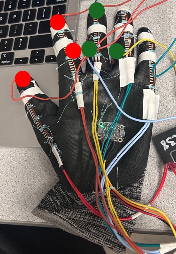
Contact Sensor Configuration - Each circle represents a copper foil (Red indicates 3.3 V, and Green are GPIO inputs)
The sensors are configured in a pull-up way. The red circles are copper foils wired to 3.3 V power pin, while the green circles are copper foils connected to GPIO inputs. As red and green contacts, the GPIO input should return a HIGH reading, indicating two fingers contact. This is useful to identify letters that differ only in fingers contact such as U and V.
Beside sensors for detecting gesture, VGA and a button is used to display the corresponding letters detected. We connected a Raspberry Pi debugger to print detected letters on the serial monitor. And the user can press the button to print the letter detected to the VGA screen. Below is an example of printed "HELLO WORLD".
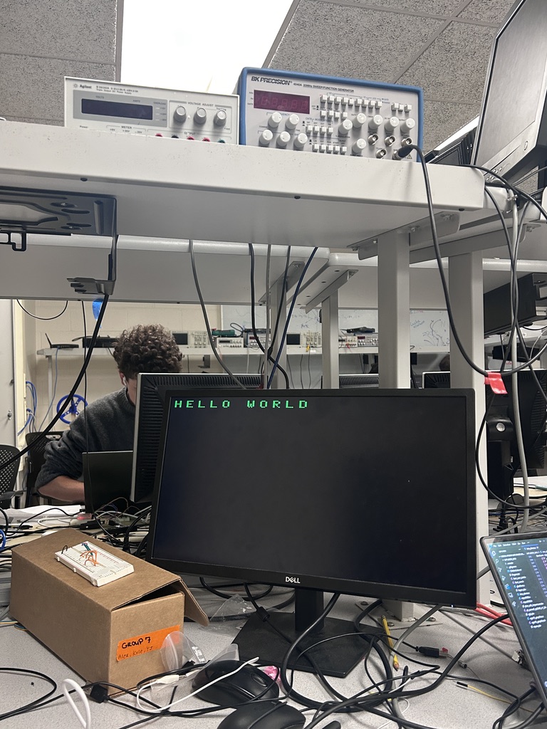
HELLO WORLD printed on VGA screen
Software Design
Gesture Recognition Framework
We implemented a structured approach to match hand positions to predefined signs using a comprehensive data structure. Each gesture is defined by a combination of finger positions (categorized as straight, half-bent, or fully bent for each finger), hand orientation data from the IMU (when applicable), and contact points between fingers (detected through contact sensors). This structured representation allows us to efficiently compare incoming sensor data against our library of recognized signs.
Mathematical Foundation
The system relies on several mathematical techniques to process sensor data accurately. We utilize 15.16 fixed-point representation for all our calculations, which allocates 15 bits for the integer part and 16 bits for the fractional part. This approach achieves high precision while avoiding the computational overhead of floating-point operations on the microcontroller.
To reduce noise in accelerometer readings, we implement a first-order IIR (Infinite Impulse Response) low-pass filter. This filter is described by the equation: y[n] = α·y[n-1] + (1-α)·x[n], where y[n] is the filtered output, y[n-1] is the previous filtered value, x[n] is the current input, and α is a smoothing factor (0.35 in our implementation). We optimize this calculation using bit-shifting operations to improve performance on the microcontroller.
For determining hand orientation, we use arctangent functions on the accelerometer data. Specifically, we calculate pitch (rotation around the y-axis) using atan2(-ax, az), roll (rotation around the x-axis) using atan2(az, -ay), and yaw (rotation around the z-axis) using atan2(ax, ay). These calculations convert the raw accelerometer readings into meaningful angular measurements in degrees, which are essential for distinguishing between gestures with similar finger positions but different hand orientations.
Additionally, we implemented a complementary filter that combines accelerometer and gyroscope data to achieve more stable orientation tracking. This filter is described by the equation: angle = 0.999 × (angle + gyro_data × dt) + 0.001 × accel_angle. The gyroscope provides accurate short-term measurements but suffers from drift over time, while the accelerometer provides absolute but noisy orientation references. The complementary filter leverages the strengths of both sensors to provide a more reliable orientation estimate.
Gesture Detection Pipeline
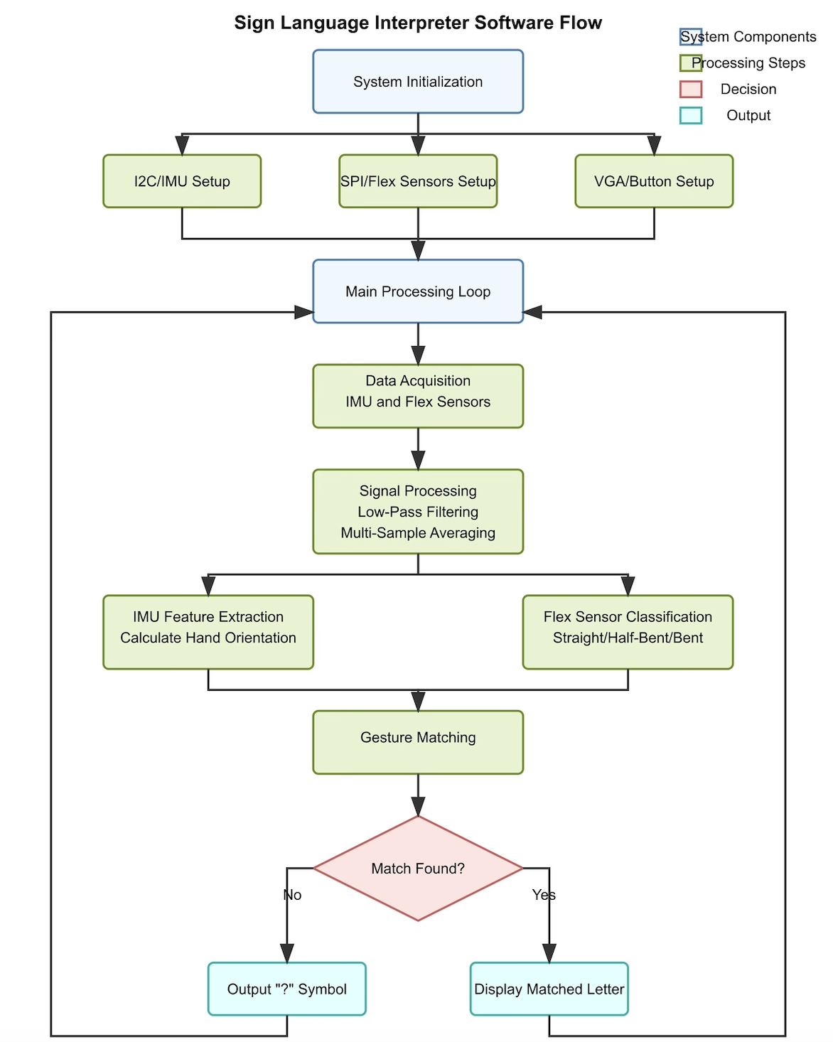
High-level diagram of the gesture detection process
Our gesture detection follows a sophisticated pipeline that begins with sensor data acquisition, where we read raw values from the flex sensors and IMU at a consistent sampling rate. The system then applies signal processing techniques, including the aforementioned filtering and averaging methods, to reduce noise and extract meaningful features from the raw data.
In the feature extraction stage, we convert these processed readings into meaningful descriptors. For flex sensors, we categorize finger positions into three states (straight, half-bent, or fully bent) based on carefully calibrated threshold values that were determined through experimental testing. For IMU data, we convert raw accelerometer and gyroscope readings into angular measurements that describe the hand's orientation in three-dimensional space.
The gesture classification stage is where the system matches these extracted features against our predefined gesture patterns. This matching process follows a hierarchical approach: first, it checks if the flex sensor patterns match; then, if contact sensors are used for a gesture, it verifies the contact points; finally, for gestures requiring specific hand orientations, it validates IMU readings within acceptable thresholds. This hierarchical approach improves efficiency by quickly eliminating non-matching gestures early in the process.
For distinguishing between similar gestures, such as 'I' and 'J' which have identical finger positions, we incorporated dynamic gesture recognition by analyzing gyroscope data to detect specific motion patterns. Once a complete match is found, the corresponding letter is identified and sent to the output generation stage, where it is displayed on the VGA screen.
Multi-threaded Architecture
We implemented our software using a multi-threaded design based on protothreads, a lightweight threading library that enables cooperative multitasking with minimal overhead. This approach allows for efficient concurrent execution of multiple tasks without the complexity of a full-fledged operating system.
Our system architecture consists of three main components: the main thread, which handles system initialization, sensor setup, and scheduling; the VGA thread, which manages the display, updates the screen with recognized gestures, and processes button inputs; and sensor processing, which is implemented within an interrupt service routine (ISR) to ensure consistent sampling rates and timely data processing.
We use semaphores for thread synchronization to ensure data consistency between the sensor processing and display components. When new sensor data is processed and a gesture is recognized, the sensor processing routine signals the VGA thread using a semaphore, which then updates the display with the recognized letter. This decoupled architecture improves responsiveness and allows the system to continue processing sensor data even while the display is being updated.
The system also incorporates a button debouncing mechanism implemented as a state machine with four states: not pressed, maybe pressed, pressed, and maybe not pressed. This approach ensures reliable button detection even with physical button bounces, enhancing the user experience when capturing gestures.
Hardware Communication
Our software interfaces with various hardware components through specialized communication protocols. We use I2C communication with the MPU6050 IMU sensor, configuring the sensor for optimal performance and regularly polling it for accelerometer and gyroscope data. For the flex sensors, we use SPI protocol to communicate with the MCP3008 analog-to-digital converter, which translates the analog resistance changes from the flex sensors into digital values that our software can process.
We also employ GPIO pins for button input and contact sensing, configuring them with appropriate pull-up or pull-down resistors to ensure reliable detection. For the VGA display, we implemented a custom driver that generates the necessary timing signals (Hsync and Vsync) and RGB color values to render text on a standard VGA monitor, providing immediate visual feedback to the user.
The software is written in C and runs on a Raspberry Pi Pico microcontroller, utilizing the RP2040 SDK. We designed the code to be modular, with distinct components handling sensor input, signal processing, gesture recognition, and display output, allowing for easy expansion to recognize more signs in the future.
Results
Our biggest struggle in this project was figuring out a consistent way to attach all of the sensors onto the glove. At first, we stitched in a circular spiral pattern, but quickly realized that the sensors would slip out of the dense stiches as we bent our fingers, and would not reinsert themselves back into the spiral. We also realized that the glove we had was meant for the left hand, which meant there were awkward air bubbles in the fingers and the top of the hand where the IMU was placed. This made it difficult to determine and maintain the "straight" thresholds.
For our demo, we had a little trouble getting detecting the letter R. Furthermore, we were not able to implement the half bent mode for the thumb because of inconsistent sensors, so we weren't able to detect 'S' vs 'O'.
Parts List
- Raspberry Pi Pico
- IMU
- Flex Sensors (5)
- Glove
- Copper contact sensors (6)
- 8 channel ADC
Total: $66.74
References
Flex SensorsIMU Datasheet
8 Channel ADC
Fall 2014: rdv28_mjl256
Fall 2018: aac94_kd333_rp426
Code Appendix
Code can be found on Github
Appendix A
The group approves this report for inclusion on the course website. The group approves the video for inclusion on the course youtube channel.
Appendix B: Work Distribution
A majority of the lab was done together in lab or somewhere on campus. Shi Gu set up and integrated the hardware, including calculations for the flex sensor circuits and setting up the ADC. Sana Chawla stitched the glove and wrote the software, including the character matching functionality and threading logic. Lulu Htutt soldered and wrote the software, including the gesture data structure and the sensor reading functionality. Overall, we worked very well as a team.