A Raspberry Pi Pico Based Rhythm Game

Project Introduction

Overview


Keyboard Hero is a rhythm game where players match on-screen notes to a five-button “keyboard” in time with a user-selected piano song.


Inspired by the popular rhythm game “Guitar Hero,” we chose to make our own rendition of it using a VGA Display and 5-button user interface resembling a keyboard. To add a layer of complexity and intrigue to the project, the song notes are not pre-programmed into the game (similar to how most rhythm games are designed) but rather they’re determined based on audio input coming from an external computer via an audio jack. We then use the RP2040 to process the audio and map the incoming audio note to the proper note color on the screen based on its fundamental frequency. To make this matter simpler, we restrict this project to playing only piano songs which use only one instrument therefore limiting audio frequency content. The audio input is also played back from a speaker in synchronization with the keyboard hits. This allows for a seamless user experience where the note colors that roll onto the screen clearly align with the note played by the song, and the music played by the speaker is in tune with the keyboard notes played by the user in real time.


Here is a Youtube video of us demoing the game!:
Rhythm Game Implemented On Raspberry Pi Pico


Design Inspiration and Rationale

Guitar Hero™ is a popular rhythm game first released in the 2000s where players use a guitar-shaped game controller to simulate guitar-playing for popular songs. The controller has five color keys (green, red, yellow, blue, and orange) on the guitar’s neck and a strum bar on the body. The idea is for the user to press down on a particular color key and hit the strum bar at the same time that a particular color key rolls down to the bottom of the screen. Music also plays in the background in tune with the notes being “played” by the guitar. Our hope for this project was to recreate a bare-bones version of this game using the tools and concepts that we learned in ECE 4760.

We chose to use a VGA graphics display to recreate a basic version of the on-screen visual with 5 note receptors on the bottom of the screen and notes rolling down from the top of the screen in sequence with the music.

Guitar Hero Notes Example
Figure 1: Guitar Hero Notes Example
VGA Display with not receptors and one note rolling down
Figure 2: VGA Display with not receptors and one note rolling down

To make things simpler, instead of using a guitar as our controller, we built a “keyboard” consisting of a small wooden pallet with 5 colored buttons - each corresponding to the five note receptors on the screen.

Guitar Hero Game controller for the Wii Console
Figure 3: Guitar Hero Game controller for the Wii Console
Keyboard with 5 colored buttons
Figure 4: Keyboard with 5 colored buttons

Audio was fed into the system via the audio jack of a computer playing a piano song, to then process the audio and play it back in synchronization with the game.

Computer transmitting audio from video via audio jack
Figure 5: Computer transmitting audio from video via audio jack

High Level Design

Background Math

Nyquist Frequency and sampling frequency for audio signals

In order to accurately sample the incoming audio signal we have to choose an apt sampling frequency. For reference, an audio signal has a frequency range between 20 Hz and 20 kHz. The Nyquist Frequency is the highest frequency that can be accurately captured for a sampled signal given a certain sampling frequency. It is considered to be equal to half of the sampling rate. Based on this we can say that if we were to consider 20 kHz to be our Nyquist frequency (since it’s the upper limit of the audio frequency range), then our sampling frequency should be 40 kHz since:


Sampling frequency = 2*(Nyquist Frequency)


The issue with a sampling frequency of 40 kHz is that it forces our system’s interrupt service routine (which handles sampling logic) to have an especially short run time which effectively limits its capabilities. Since the bulk of the audio content (particularly for piano songs) does not reside at higher frequencies, we can lower the sampling rate significantly in order to increase interrupt service routine and still maintain good quality audio sampling fidelity.

In this case, we opted for 10kHz as our Nyquist Frequency and hence our sampling frequency was 20 kHz.

Note Frequency Detection

To determine which of the five colored-notes to play on the screen, the frequency of the note being received by the system in real-time has to be measured with relative accuracy. This game is programmed for songs using notes based around middle C on Octave 4.

The frequency input is mapped to a particular color based on the frequency range “bin” it lands in. The frequency to note color mapping is explained in the table below:

In order to measure the fundamental frequency of a note being played we make use of a few features that our system affords. Because we are sampling the audio signal at a precise rate (10 ksps), and we know the exact number of audio samples that are stored in a buffer every time we detect a new note being played (2000 in this case), we effectively know the exact length of the sampling period for each note.


Sampling time period

= (sample buffer size) / (sampling rate)

= (2,000 samples) / (10,000 samples per second)

= 0.2 seconds


We then measure the number of “crossovers” that occur during the sampling period. Assuming we were to have a signal that monotonically increases and monotonically decreases each cycle, we can count the number of times that the signal samples jump from below the mean value of the signal to above the mean value. Understanding that every two crossovers correspond to a single signal cycle, we can measure the frequency of the signal as follows:


Frequency = [ (# of crossovers) / 2 ] / (Sampling time period)


It’s important to note that the fact that the system only requires each detected frequency be “binned” to a certain frequency range in order to coordinate a note frequency to a note color means that the system allows for a certain margin of error for the frequency measurement in the order of +/- 10s of Hz. This makes it so that the frequency measurement, although it needs to be relatively accurate, does not have to be perfect and can account for some degree of miscalculation.

Low Pass Filtering

As mentioned above, this frequency measurement technique assumes that the signal be monotonically increasing or monotonically decreasing each half-cycle to ensure an accurate measurement of the number of crossovers. When a piano note plays (although it is easy to detect its fundamental frequency upon inspection), it contains noticeable higher order harmonics that make it susceptible to a higher number of crossovers than what is needed to accurately measure the notes fundamental frequency. To mitigate this, this system uses a software-implemented digital low-pass filter which low-passes the audio adc input being fed into the system and outputs a signal that, although not exactly a pure tone, does monotonically increase and decrease with considerable consistency. This ensures a relatively accurate measurement of the number of crossovers.

The digital low pass filter is implemented by running each audio input sample through the following line of code:


filter_lp_output = filter_lp_output + ((filter_lp_input - filter_lp_output) >> 3);


filter_lp_input is the input sample and filter_lp_output is the output sample. As shown, the filter makes use of the previous output sample to process the upcoming input sample.

The number of bits by which the difference between the input and output sample is shifted is of similar functionality as the RC time constant in an RC low-pass filter circuit. The greater the number of bits, the lower the effective “cutoff frequency” of this filter is. Using an especially high number of bits can degrade the signal however. Three bits seemed like a good number given how the signal inputs are twelve bits in total. Three bits is enough to get rid of the higher order harmonics without degrading the signal too much.

A more in-depth technical discussion is given in this page:

Digital Lowpass Filters – Van Hunter Adams

Logical Structure

Hardware System Flowchart
Figure 6: Hardware System Flowchart

The system is structured into five components:

Computer with audio input: A computer is used to supply audio input into the Audio Processing Raspberry Pi Pico via an audio jack that feeds a signal into the ADC. For the purposes of this project, the audio being fed in is a piano song.

Audio Processing Raspberry Pi Pico Microcontroller: We use one RP Pico to take care of audio processing. This pico sends the audio input it receives from the computer into a speaker with slight time delay to allow for synchronization with the VGA graphics. It also takes care of detecting whenever a new note is played and the frequency of said note. Depending on the frequency, it sends a number between 0 and 4 to the VGA Graphics RP Pico via UART.

Each number corresponds to one of the five frequency “bins.” This bin number then gets mapped to one of the five notes that show up on the VGA display. Each time a new note is detected, a new note should show up on the VGA screen with the correct frequency to note color mapping.

VGA Graphics Raspberry Pi Pico Microcontroller: We use another RP Pico to handle the VGA Graphics processing. This includes generating the five note receptors, scroll-down notes, a score bar, and prompted instructions. As mentioned above, the scroll-down notes are generated based on the timing and contents of UART input.

VGA Display: The Video Graphics Array (VGA) Display is the physical machine used to display the game. It has 480 x 640 resolution and hooks up to the pico using a VGA connector.

Speaker: We use a speaker to play the input music in tune with the VGA Display.

Keyboard: The keyboard contains five colored buttons corresponding to each of the note receptors on the VGA screen. Each time a button is pressed, it pulls down a GPIO input on the VGA Graphics Pico. The VGA Graphics Pico reads the Keyboard note hit and determines whether it was timed well enough to hit the note rolling down the screen on time.

Hardware/Software Tradeoffs

One particular limitation we faced was a restriction on RAM memory. Given the sizeable amount of RAM we needed to both buffer 1.5 seconds worth of 12-bit audio samples at a 10 Khz sampling frequency, and run the VGA Graphics display, we opted for using two separate Picos. This allows for twice the RAM memory availability, at minimal increase in project complexity.

Patents, Copyrights, & Trademarks

This game is an original work inspired by Guitar Hero™; however, it is an independent project with no affiliation, endorsement, or association with Guitar Hero™ or its rights holders. All trademarks, copyrights, and other intellectual property related to Guitar Hero™ remain the sole property of their respective owners, and this game does not claim or imply any ownership of, or infringement upon, those rights.

Hardware Design

Hardware System Overview Diagram
Figure 7: Hardware System Overview Diagram

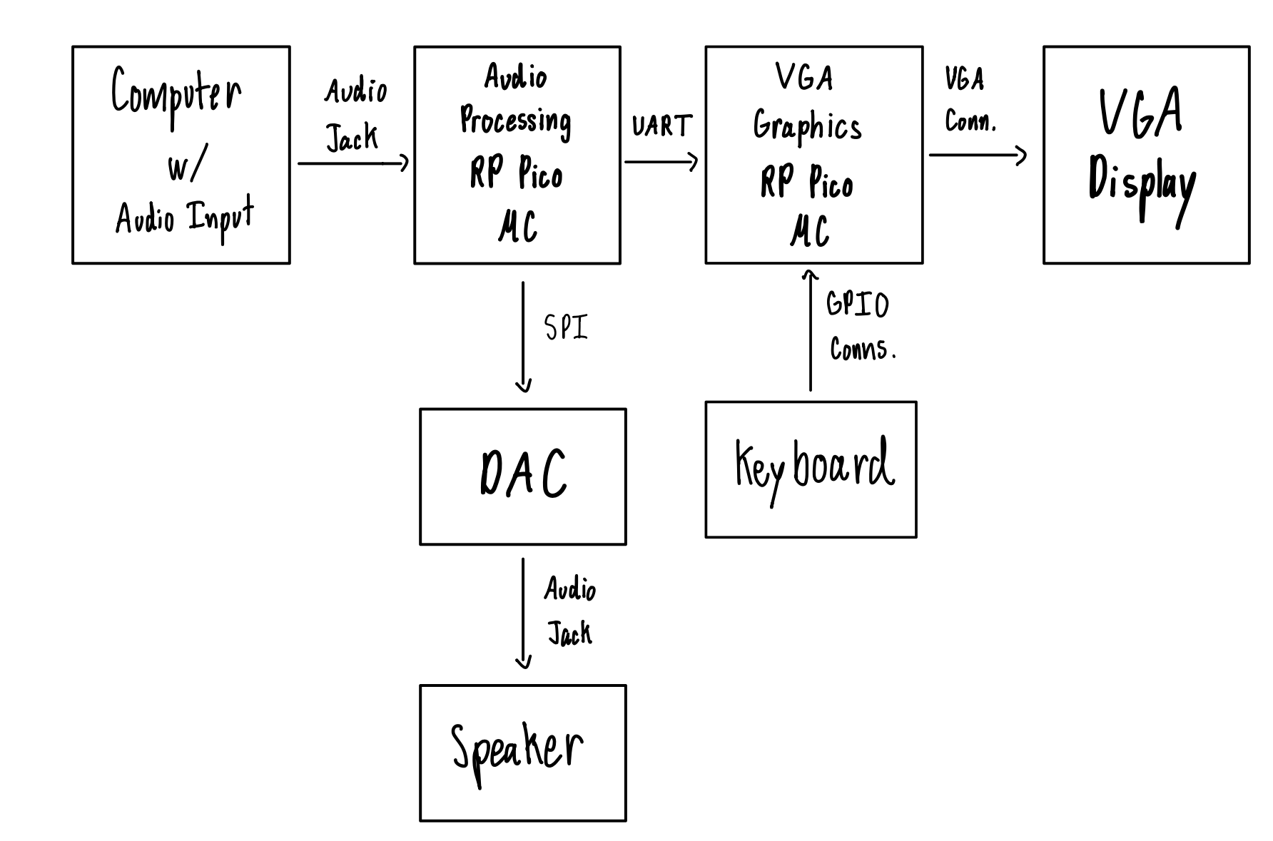
For this hardware description we will walk through each of the system subsections sequentially.

Computer audio input into Audio Processing Pico ADC

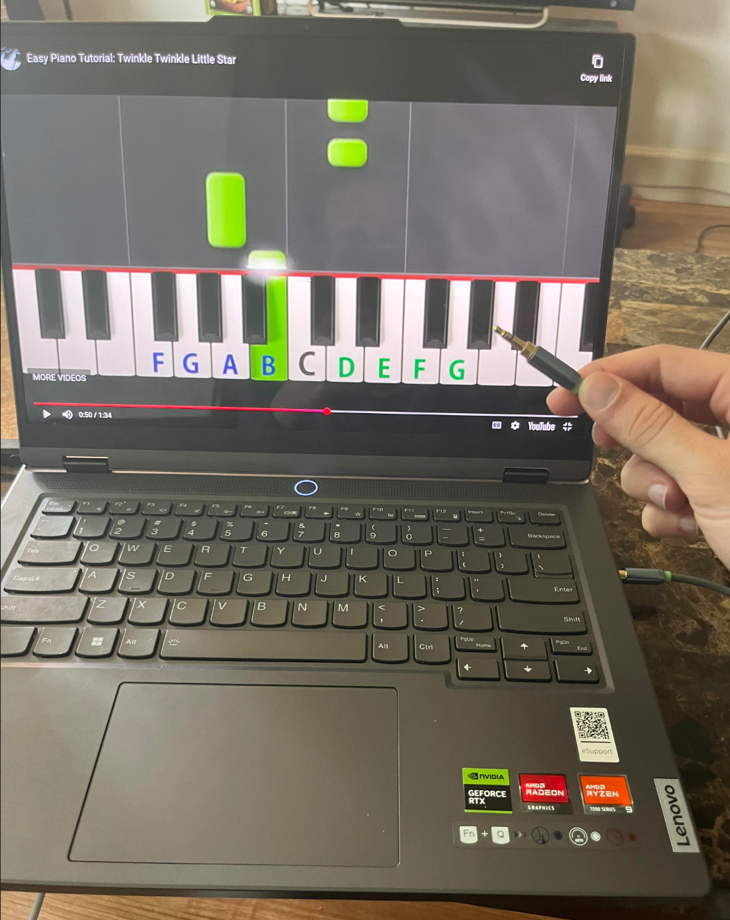
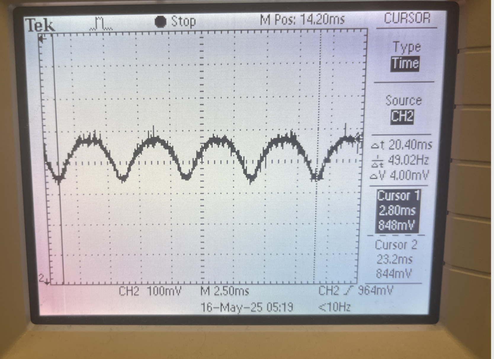
The song audio is initially sent out from the computer via an audio cable hooked up to an audio jack. The song audio initially has a mean value of zero volts with the signal oscillating between both positive and negative values.

Input Audio Signal with mean of 0V
Figure 8: Input Audio Signal with mean of 0V

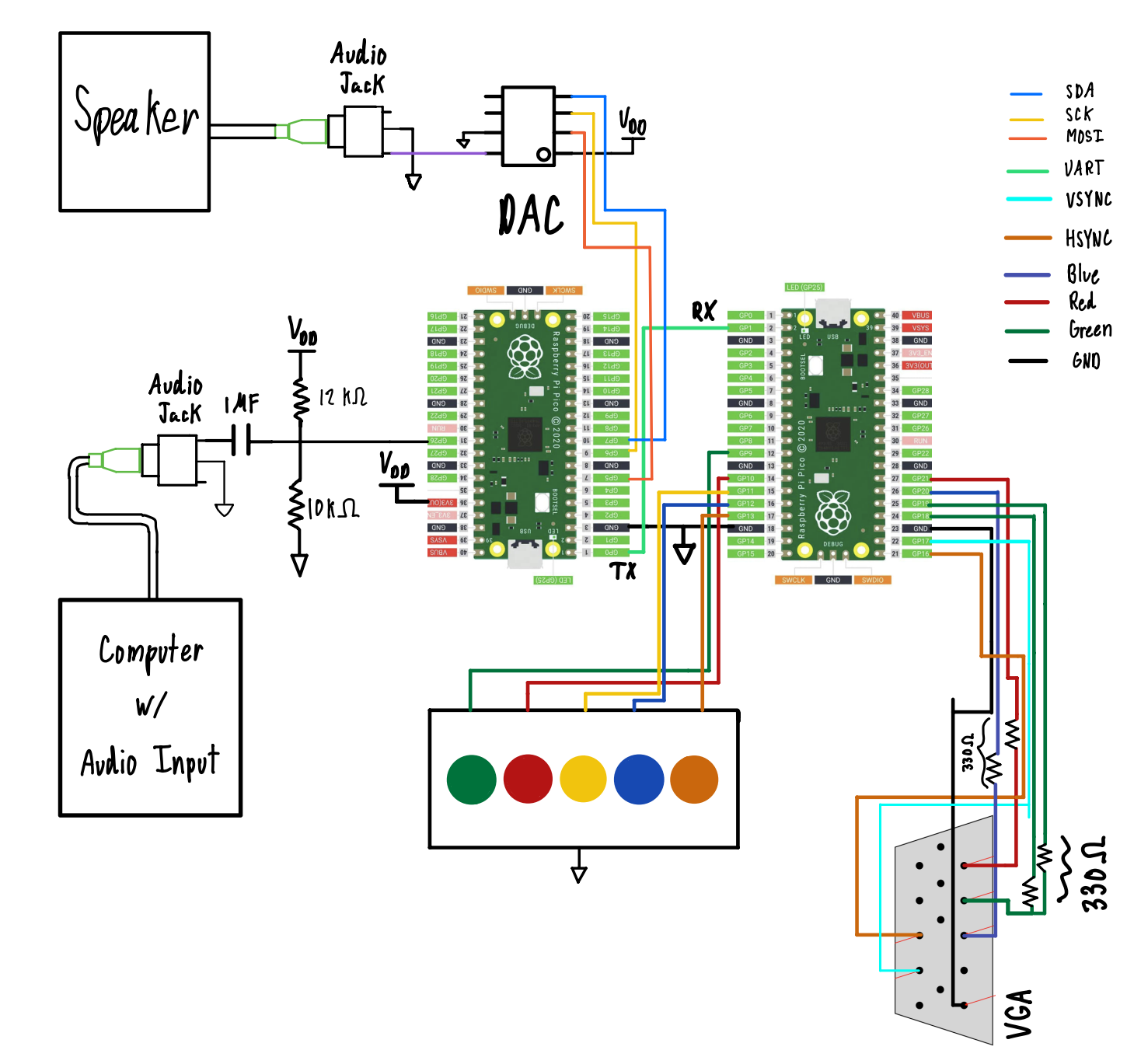
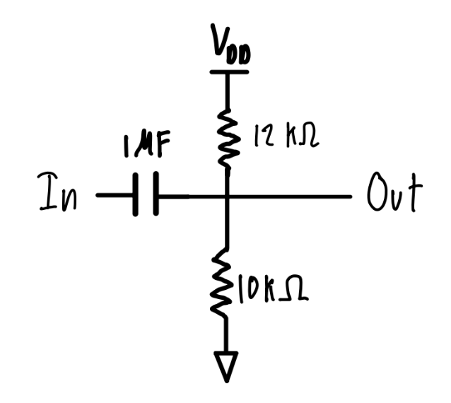
We then implement a sub-circuit containing a bypass capacitor along with a resistor divider to filter out the DC content of the signal and effectively take the AC content to then shift it up to a prescribed mean value determined by the voltage divider.

Voltage Bias Subcircuit
Figure 9: Voltage Bias Subcircuit

The mean value is calculated as follows based on the fact that VDD is 3.3V:


Mean value = (10 kOhms)/ (12 kOhms + 10 kOhms)*(3.3V) = 1.5V


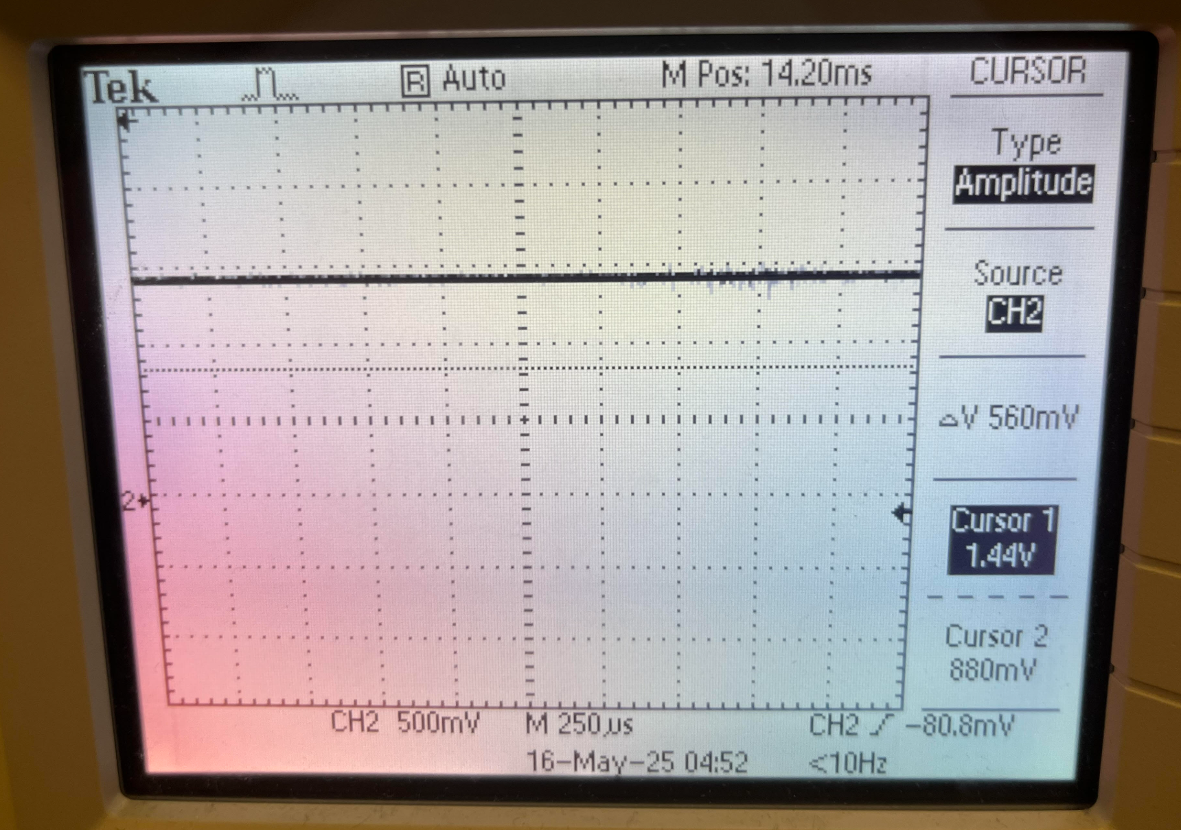
*In practice the mean value is 1.44V

Mean Voltage Bias measured at 1.44V
Figure 10: Mean Voltage Bias measured at 1.44V
Biased Audio Signal showing global maximum of 2.74V (within range)
Figure 11: Biased Audio Signal showing global maximum of 2.74V (within range)
Biased Audio Signal showing global minimum of 0.1V (within range)
Figure 12: Biased Audio Signal showing global minimum of 0.1V (within range)

By shifting up the mean value to this level we ensure that the audio signal is contained within the 0V to 3.3V range required for ADC input value reading without the fear of clipping.

Audio Processing Pico SPI to DAC

The Audio processing Pico hooks up to the DAC via SPI communication. Since communication only occurs from the pico to the DAC, and not vice versa, only MOSI is implemented. The connections also include the standard VDD, GND, SDA, and SCK connections. The DAC then outputs the time delayed signal to the speaker via an audio jack/cable connection.

Audio Processing Pico UART TX to VGA Graphics Pico UART RX

In order for the VGA Graphics Pico to determine when a new note should show up on the screen, and which note should show up on the screen, it has to receive this information from the Audio Processing Pico. The information flows between the two of them using a UART connection. Given the low frequency of the information flow (about 1 Hz) and the fact that UART is easy to implement for these purposes it seemed like a good choice for communication. In this case the UART connection only consists of a ground line and a single TX/RX line since the Audio Processing Pico sends information to the VGA Graphics Pico but not vice versa.

Keyboard to VGA Graphics Pico

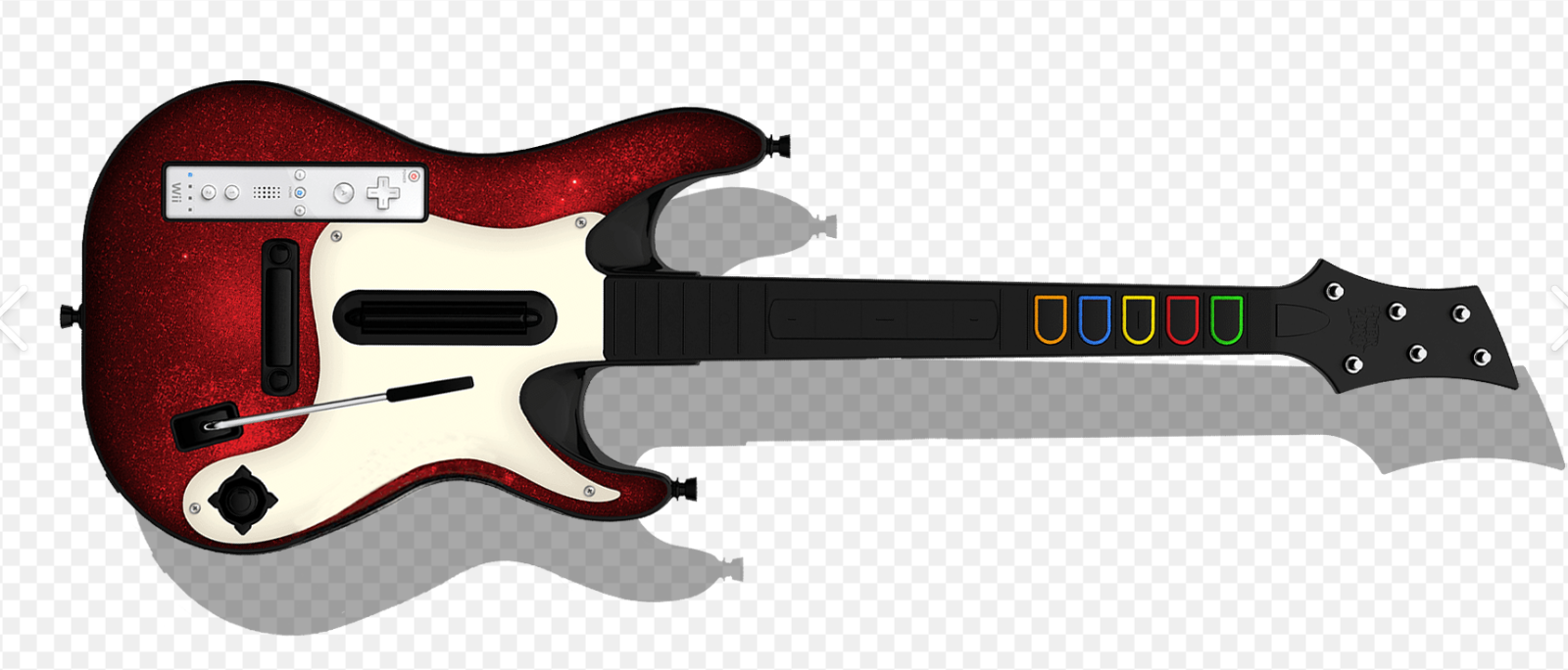
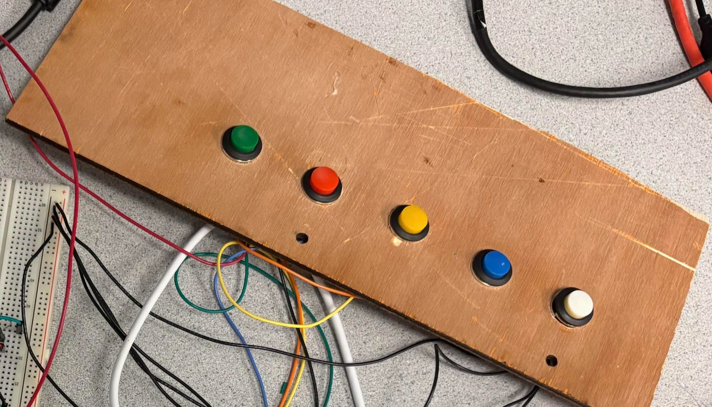
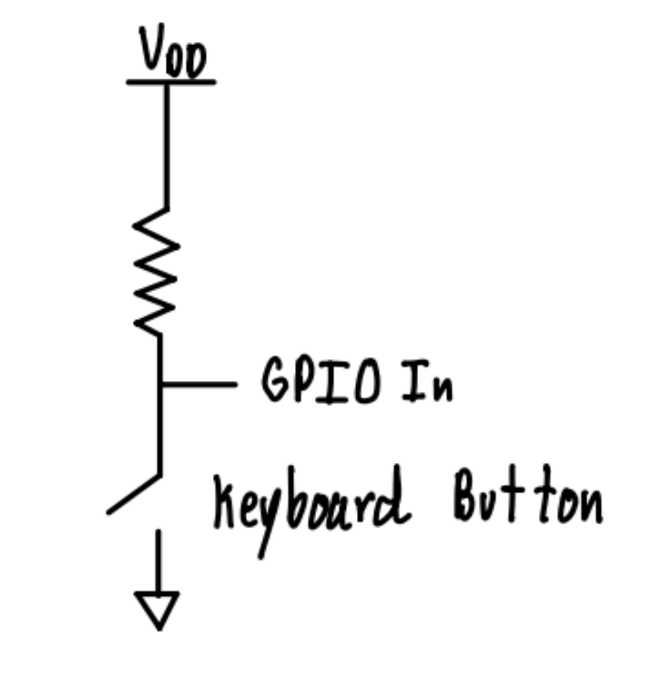
The VGA Graphics Pico is able to receive user input via the five buttons on the keyboard that act as pull down switches. The GPIOs in the Pico are pulled high by default, by means of an internal pull-up resistor. The GPIOs are also connected to the five buttons on the keyboard that are each connected to ground on their opposite pin connection. When the buttons are pressed they are pulled low. This allows the system to read when a particular button is pressed by the user.

GPIO to Keyboard pull-down switch sub-circuit
Figure 13: GPIO to Keyboard pull-down switch sub-circuit

Keyboard to VGA Graphics Pico

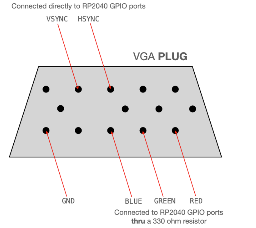
The VGA Graphics Pico hooks up to the VGA Display connector as per the following image:

VGA connections
Figure 14: VGA connections

More information can be found on this page:
VGA Driver for RP2040 – Van Hunter Adams

Software Design

Program Details for Audio Processing Pico

High-level software structure:

The code for this project is divided into four main sections:


1. Global setup section

2. main() function

3. alarm_irq()

4. Helper functions


At the start of the code, we have a section dedicated to including libraries, defining macros, and initializing global variables and arrays. We’re referring to this as the global setup section.

The main() function takes care of initializing the GPIO pins, UART connection, SPI, the ADC, LEDs, and the interrupt timer.

alarm_irq() is an interrupt service routine that handles audio sampling and processing. It is triggered by an alarm that operates at 10 Khz (our sampling frequency of choice) and, during each cycle, it takes an ADC sample, updates different buffers, outputs audio to the DAC, and handles logic used for frequency measurement.

This code makes use of a couple of helper functions: bandpass(), and crossover_LEDs().

bandpass() takes in a frequency value in the form of a float as its parameter and then determines which of the five “bins” a particular frequency corresponds to. It then outputs a number between 0 and 4 accordingly (This is what is sent over UART to the other pico).

crossover_LEDS() is a function that was implemented for debugging purposes during the prototyping phase. We needed a way to display the number of crossovers that the system was counting to understand the frequency that it was measuring. We could not use printf() since it was too computationally expensive to implement in an interrupt service routine so instead we opted to use some LEDs to output the crossover amount measurement in binary. This proved to be a simple effective solution to a tough stumbling block.


alarm_irq():

The global setup section and the main() function are both fairly straightforward as they consist primarily of variable instantiations and setup functions as mentioned in the section above.

The one section of the code worth elaborating on is the alarm_irq function. And its underlying logic. The interrupt service routine operates at 20 KHz to account for the necessary audio sampling rate of our system (refer to Background Math Section for more details). Each cycle it fulfills a couple of functionalities.

For one, a 22,000 element long audio sample buffer is updated by one value during each ISR cycle. This buffer allows for audio samples to be read from the ADC in real time, and then transmitted to the speaker with a 2.2 second delay ( (22,000 samples / 10,000 samples per second) = 2.2 s) through a clever use of indexing. There’s an index for placing a new input ADC sample and an index for the audio sample within the buffer that’s being output to the DAC. The input index is initialized to 0 and the output index is initialized to one. Each cycle, each index increases in size by one until wrapping around from 21,999 to 0. As such, the buffer has a FIFO functionality. Since the buffer array is initialized to all zeros at the start, this means that the system begins by outputting 0 values (silence) to the DAC for the duration of 2.2 seconds. It then starts outputting the audio data from 2.2 seconds prior continually hence creating a consistent fixed delay. This 2.2 second delay accounts for the delay between the note showing up at the top of the screen, and the note rolling down to the note receptor.

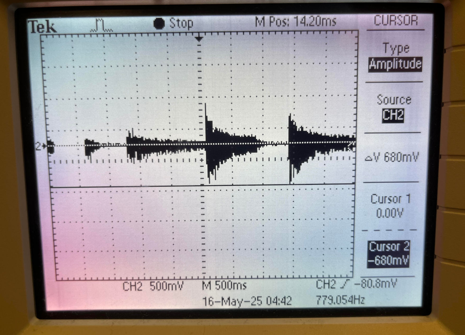
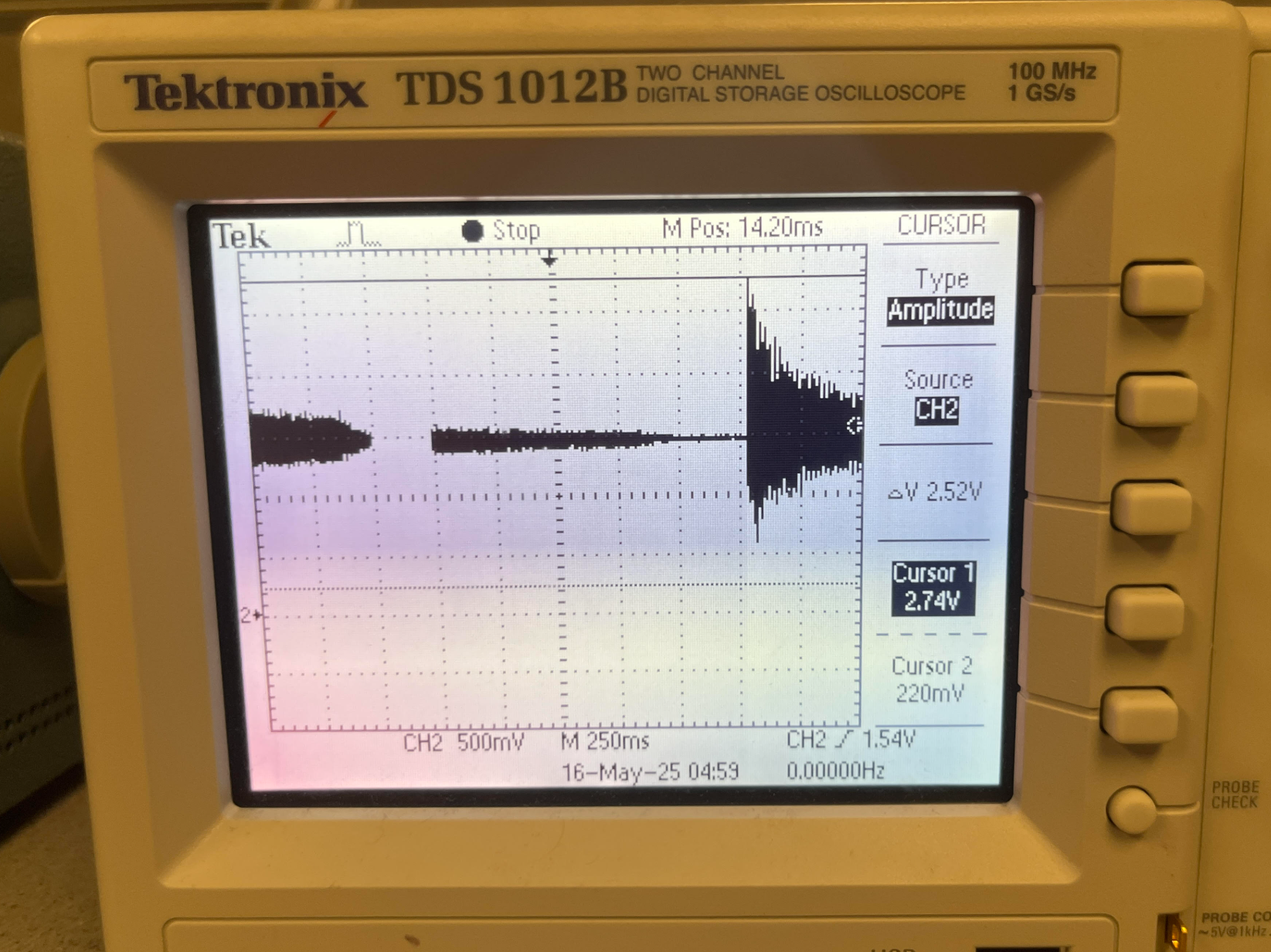
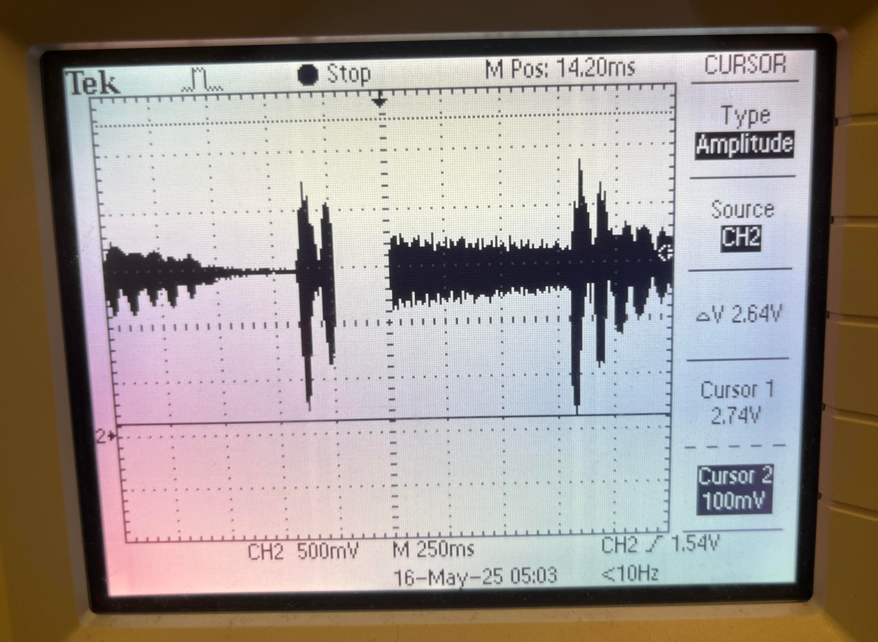
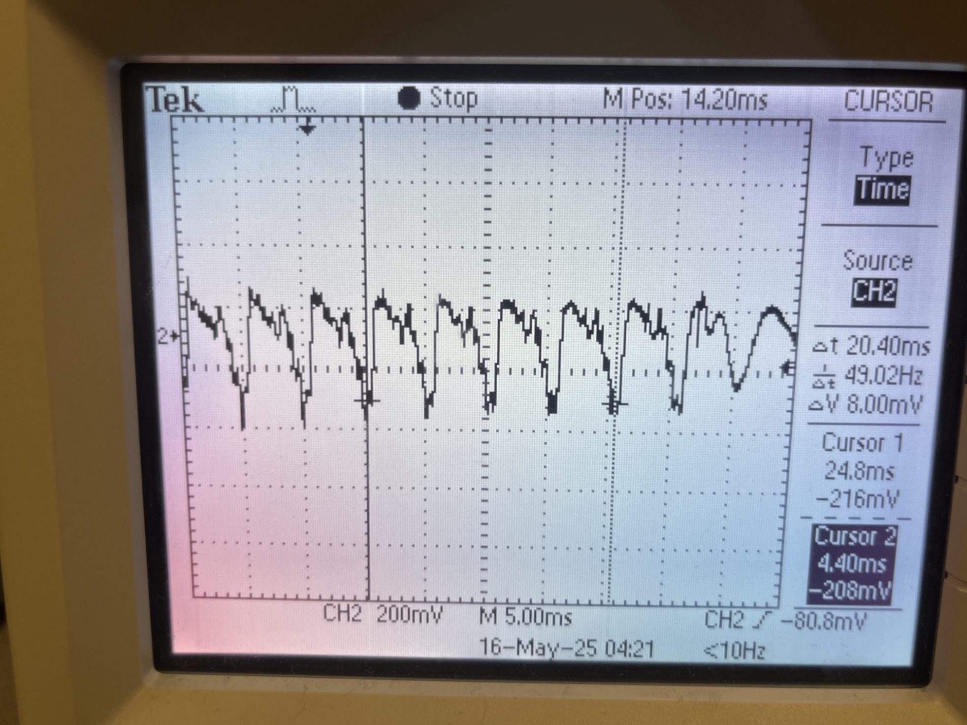
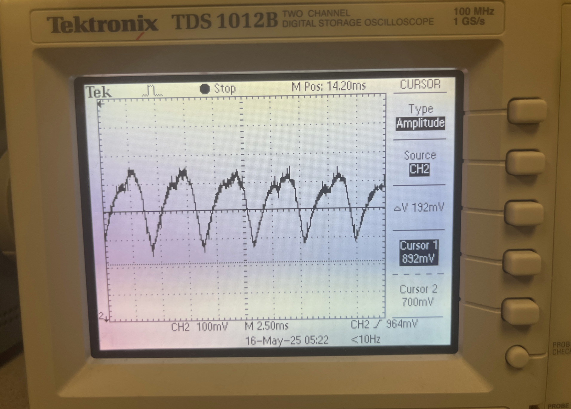
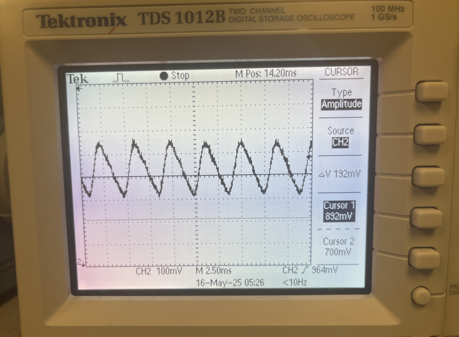
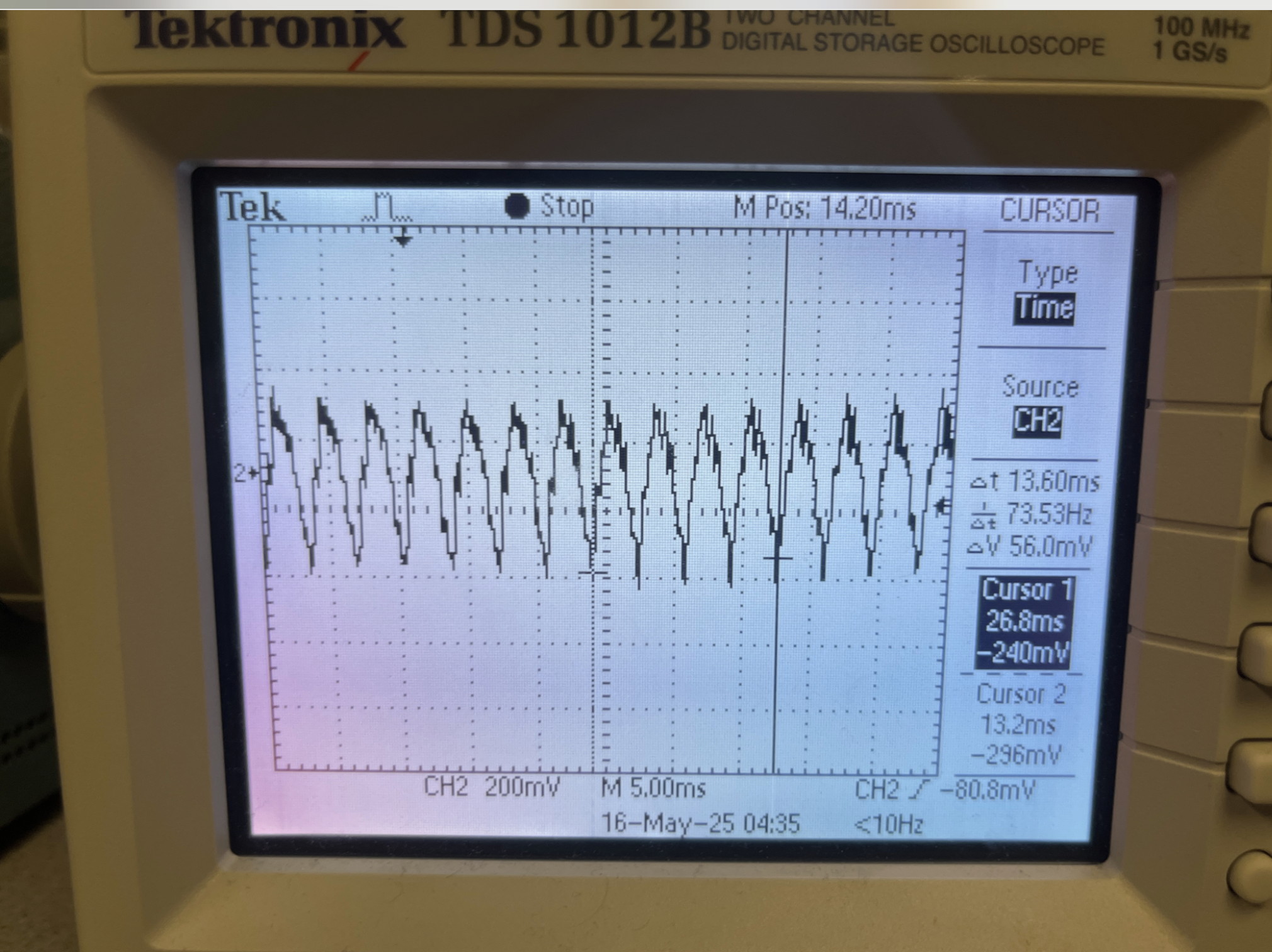
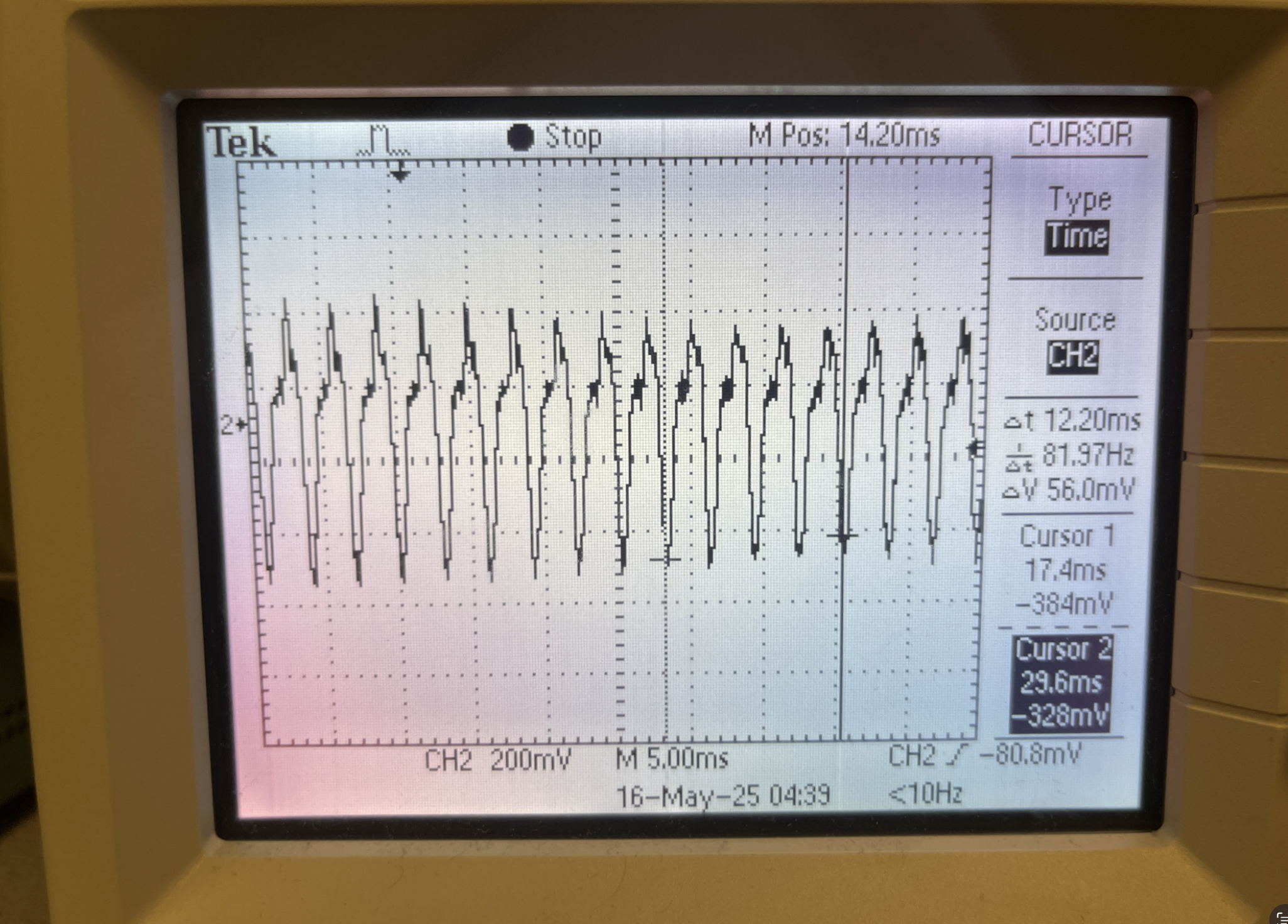
The service routine also note detection logic. Each cycle, the ISR detects whether a new note has been played by the piano audio (allowing for a minimum 50 ms delay in between detections) based on threshold voltage logic. Piano notes, upon first being played, reach their maximum amplitude and then taper off over time. Given this behavior we determined optimal voltage threshold values that are consistently reached at the start of each note, and are not reached again past the 50 ms mark. This ensures that a note is only detected once each time it’s played. We determined proper threshold values to be 1.65V and 1.23V based on experimental inspection. These are equidistant values above and below the mean value of 1.44V. If either of them are surpassed, and the 50ms condition is not of concern, a new note is detected.

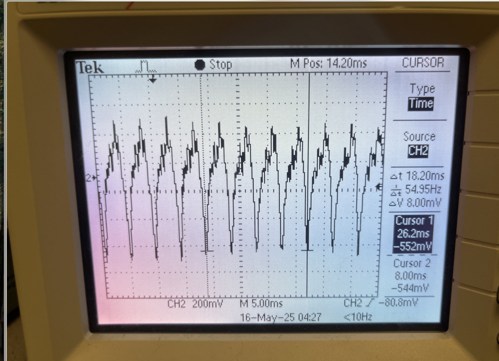
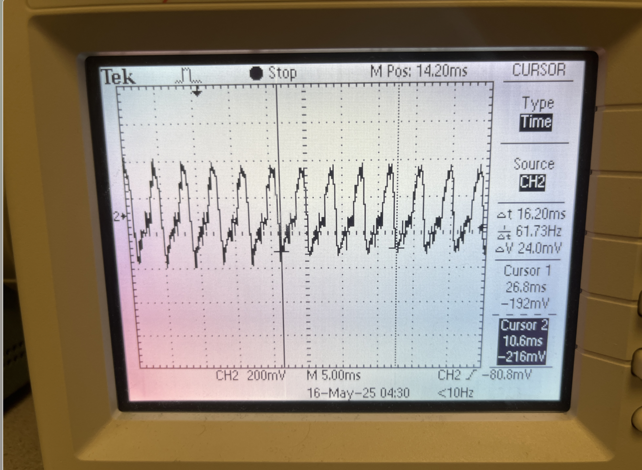
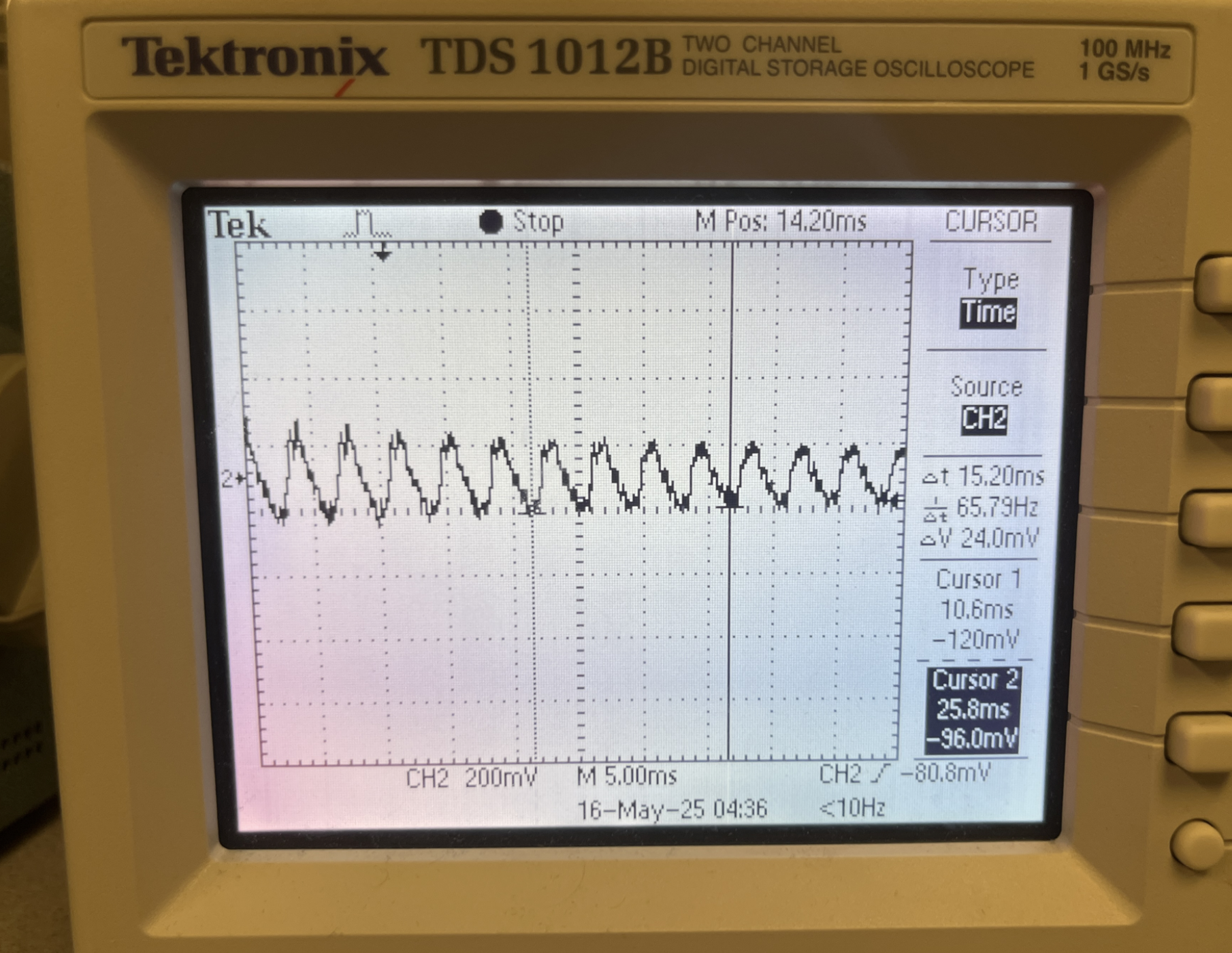
Lastly, the ISR handles frequency detection logic (check Background math section for more information). Each time a new note is played, 4000 sequential low-passed (refer to Background math section for more information) samples are placed in a sample buffer array. Once they are all acquired, the software uses a for-loop to iterate through the array and count the number of jumps that occur from below the mean value to above the mean value of the signal or vice versa. With this, we’re able to attain the number of crossovers that occur, and, based on this, along with the prescribed sampling rate and array length, are able to calculate the frequency of the signal to a good degree of accuracy.

It is worth mentioning that each time a frequency is measured using the technique above, the frequency measurement is sent through the bandpass() function and the 0-4 return value is sent via UART to the counterpart Pico.

Program Details for VGA Graphics Pico


Main System Functions for the Game


main(): The entry point of the program that can initialize all the components like the VGA, UART, and GPIO that can allow for the original game state to be set, animation and GPIO threads can then be added to the scheduler, and starts the program execution.

initUART(): Begins the initialization of the UART communication between our two Picos with it being at 115200 baud rate for the interrupt-driven type reception, which allows for us to have the VGA Pico obtain the note data from our Pico that is being used for the audio processing.

initGPIO(): Allows for our GPIO pins to be initialized for the five physical buttons with there being pull-up resistors, while also establishing the keyboard controller interface that allows for the players of our game to effectively hit the notes on screen.

initVGA(): Initializes our VGA display system for enabling the graphics to render for our 640x480 VGA display that is acting as our screen for the game.


Game Physics Functions


spawnNote(): Creates a new falling note at the top of the screen from either using the UART connection from the audio Pico or randomly generated notes that was done during our testing process, which allowed it to have its position and color based on the frequency determined band from the audio Pico.

updateNotes(): The major animation function that allows us to handle the movement of all the active notes down the screen, while handling the collision physics when buttons are being pushed down, updates the score for when the notes are hit, and allows for the gam over screen to show on the screen once the song is finished.

checkButtonPressed(): Button debouncing logic becomes implemented to make sure that quick or noisy button presses are designed as single and clean inputs.

checkNoteHit(): Sees if the press of the button is aligned with our designed collision area, which is 20 pixels above to 10 pixels below the button line, while registering successful hits and causing the score to update for us as well.

recordHit(): Increments the player's score when a note is successfully hit, while it also updates the percentage display, while also describes there being a confirmation of hit.


Interface Functions


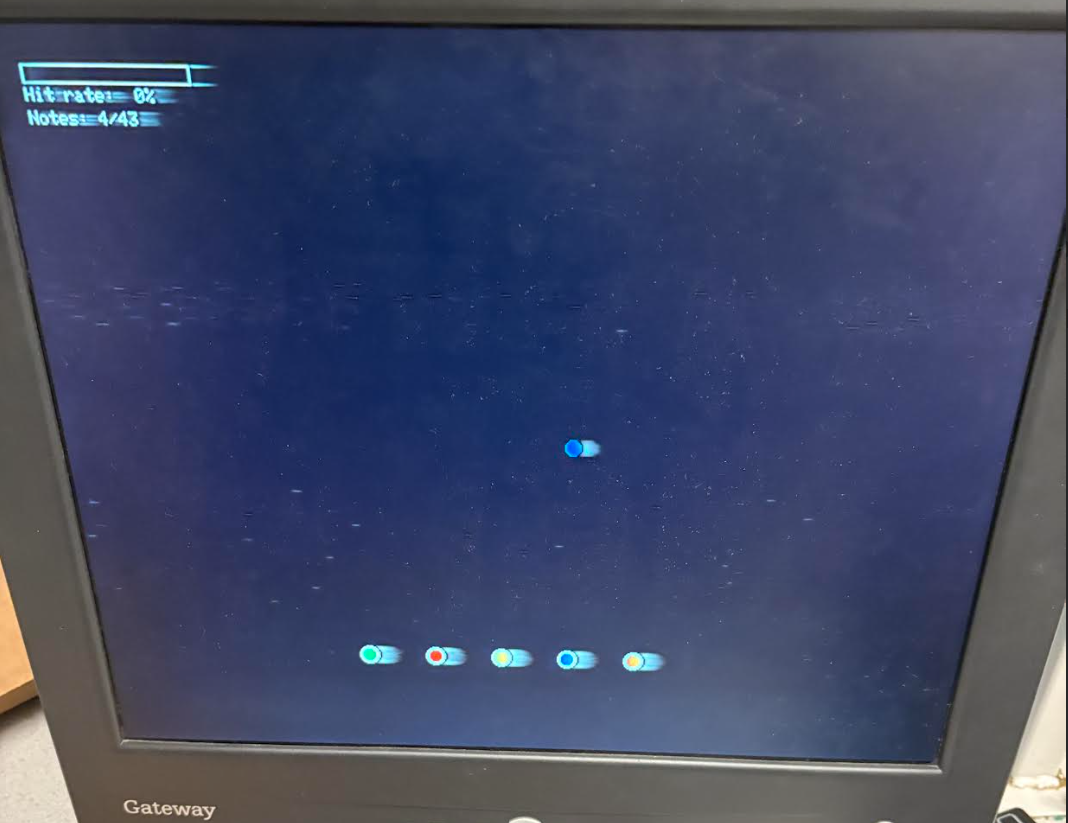
drawButtons(): Draws the five colored buttons at the bottom of the screen that go with the five note frequencies areas for us where the falling notes will move down toward.

highlightButton(): Provides visual success when a button is hit at the moment a note reaches the button at the bottom while also outlining the button with a green outline 300ms for allowing ther player to be provided with immediate feedback.

restoreButton(): Resets a button's appearance back to being back to the original appearance once the button is finished outlining in green.

updateScore(): Keeps the updating of the score display when a note is hit or missed, including a visual progress bar that fills based on player performance.

drawGameOverScreen(): Shows the player the final score and hit percentage when all notes have beee finished for a song, while showing "GAME OVER!" and showing that any of the colored buttons can be pressed to restart the game.

resetGame(): All the game variables become reinitialized, with the screen clearing, and new game becomes prepared.


Thread Management Functions


protothread_gpio(): A thread that keeps monitoring the physical button states, handles the button presses for game mechanics, and accounts for the game state transitions like restart and the start of the game.

protothread_anim(): The main animation thread that keeps the frame rate timing, updates our note positions, manages button highlighting for us as well, and makes sure that there keeps being the necessary visual performance while being operated at 30fps.


UART Communication Functions


on_uart_rx():The interrupt handler that is able to take in the incoming UART data from the audio Pico, while taking in the note frequency information from the button index of 0-4 when a new note ends up becoming detected.


*For reference - our code can be referred to in Appendix B

Results of the Design

System Architecture Performance Reflection

Our implementation of our game called Keyboard Hero, which was our version of implementing concepts learned from ECE 4760 as well as previously taken ECE classes for simulating Guitar Hero. Overall, we were able to successfully link one Raspberry Pi Pico dedicated to audio processing and another Raspberry Pi Pico that would be for handling the visual display and game play physics. From being able to distribute the computations across two microcontrollers, we were able to successfully achieve the parallel processing capabilities that would not have been feasible whe having a single Pico approach. The audio processing Pico was able to function at a 250MHz clock speed after overclocking from the default 125MHz to make the proper sampling rates for reliable frequency detection, while the VGA display Pico stayed at 125MHz standard clock speeds for sufficient graphic rendering. From the UART connection linking the two picos, this allowed us to achieve successful communication and timing between the two picos to max the rhythm of our input song.

Audio Detection Algorithm Results

The audio detection algorithm implemented on one of the picos showed to us precision across the target frequency range. This system for this was able to provide for the complex overall frequency detection where there were the components of the initial analog signal acquisition through the ADC at pin 27, next would be the preliminary low-pass filtering stage to reduce noise that was existing, and then zero-crossing detection for being able to figure ourt the fundamental frequency. For "Twinkle Twinkle Little Star" in the third and fourth octaves based on the song we used, we made sure to encompass the notes of G3 (196Hz), A3 (220Hz), B3 (247Hz), C4 (261.63 HZ), D4 (294Hz), and E4 (329.63Hz). We determined our cutoff frequencies for the notes from our chart below:

Music Note to Frequency Chart Used for Piano songs
Figure 15: Music Note to Frequency Chart Used for Piano songs

For our testing to see about the notes that were being played, the video we used that we were planning to show for the demo displayed the actual piano note that was being played to allow for us to have a check the note being shown to be played on the piano with the frequency for our filtering process

Piano note D4 being played for the Twinkle Twinkle Little Star piano version
Figure 16: Piano note "D4" being played for the "Twinkle Twinkle Little Star" piano version to allow for us to check the frequency corresponding to each note

For our frequency analysis, we were able to see that each of the not low passed versions depict that the fundamental frequency for them align with each of the frequencies of notes from the chart. Then, we were able to take the low passed version of these audio signals to be able to show the way that the higher order harmonics were able to be eliminated to be able to measure an accurate amount of crossovers.

Circuit Setup for being able to low pass the output frequency
Figure 17: Circuit Setup for reading audio signal on Pico ADC
Oscilloscope reading for the not low passed version of the G3 audio sigal for the note
Figure 18: Oscillopscore reading for the not low passed version of the G3 audio signal for the note

From, this we can calculate the frequency as 49Hz x 4 = 196 HZ, which correlates with the G3 frequency value of 196 Hz. The four comes from the four complete cycles we are measuring for here.

Low passed version of the G3 note
Figure 19: Low passed version for the same note G3 to be able to mitigate the higher harmonics and make sure we are able to allow for the fundamental frequency to be detected
Non-low passed version of the A3 note
Figure 20: Non-low passed version for the note A3
Low passed version of the note A3
Figure 21: Low passed version of the note A3

One aspect to note here is that the 892 mV iis the equivalenti of 1.44V for the ADC output.

We were able to determine that this was the piano note A in the third octave from:

55Hz x 4 = 220Hz, which can be referred back to the chart as A3.

B3 note signal shown here without low pass filtering that would be used later for filtering out the higher order harmonics
Figure 22: B3 note signal shown here without low pass filtering occurring that would be used later for filtering out the higher order harmonics
Piano note B3 low passed
Figure 23: Piano note B3 now low passed to filter out the higher order harmonics

To show again here, we were able to determine that this was the note B in the third octave from performing 61.7Hz x 4 = 246.8 Hz where B3 = 246.94Hz showing how close this was again to corresponding to note B i the third octave. We performed the low pass filter on all of the input notes, but these were examples that we were looking to highlight in how the low pass filtering can be visually seen to eliminate the higher order harmoics

C4 note signal not low passed
Figure 24: Not low passed signal for the note C4

We can again see the frequency correlating with the note C4 from the relation 65.8Hz x 4 beig 261.6, which correlates to the piano note C in the fourth octave as referenced from the chart.

D4 piano note sigal not low passed
Figure 25: D4 piano note sigal not low passed

This was able to be shown to be the piano note D in the fourth octave based o the relation of 73.5Hz x 4 = 294Hz, which would again correlate based on our chart from adove that is the note D in the fourth octave's fundamental frequency.

E4 audio signal when not low passed
Figure 26: E4 audio signal when not low passed

Furthermore, the highest frequency of note for our "Twinkle Twinkle Little Star" input song was the note E in the fourth octave, which can be seen from the relation 82Hz x 4. This is 328Hz, which is very close to the 329.63Hz referenced by our chart.

UART Communication and Visual Results

The UART communication was able to stay reliable throughout the testing process. We were able to configure it at 115200 baud with there being 8 data bits, 1 stop bit, and no parity where the serial link was able to give to us more than enough bandwidth for the requirements of our game. We were able to detect a note that was transmitted as a single byte (values 0-4 corresponding to our five target frequency areas) where there were also lightbulbs showcasing the value of the not being transmitted as well.

The simple protocol that was done of transmitting a single byte per note detection was able to be shown to be both robust and efficient while avoiding the more complicated nature of other communication methods that were not needed for the requirements of our project.

The display Pico maintained consistent frame rate as our game was playing where we were abler to keep the rendering at a steady 30 frames per second without having there be dropped frames. Through working through the optimization of the drawing routines, like the fillCircle and drawCircle functions, we were able to have there being a smooth animation while allowing for memory for specific game mechanics and physics.

Safety in the Design

Our Keyboard Hero implementation incorporated specific safety measures when establishing our hardware and software components to make sure that they were enforced. At the hardware level, we were able to design the proper GPIO configurations with there being pull-up resistors for the button inputs for preventing there being floating states and the current-limiting resistors to allow for the microcontroller pins to not become damaged. For the keyboard itself for the button presses, we made sure to sufficiently sand the edges of the wood for the keyboard to ensure that players would not become hurt after using the keyboard. The software architecture had for us various protection mechanisms, like the boundary checking for all the array accesses to make sure that there were no overflows occurring and circular buffer implementations for making sure that we were using our memory as optimally as possible. Using a two pico system for us allowed for us to have useability for the miuch distant future through makig sure that issues in the audio input system would not hinder the gameplay experience. Additionally, the input handling system incorporated robust debouncing with there also being a 100ms window for limiting any erratic behavior from mechanical switch bounces. These various safety measures that we took made sure that the safety of the player was prioritized along with enjoyment during extended gameplay sessions, which allowed for the hardware components of the game to be protected as well as the safety of each player.

Note Spawning and Gameplay Physics and Mechanics

The note spawning system allowed us to see accurate timing control where the new notes were able to be spawned in at 500ms intervals to match the rhythm of our "Twinkle Twinkle Little Star" that would be used for the demo. An upper limit of 10 simultaneous on-screen notes were definitely more than enough to handle the song's note pattern as well as for future songs where the game would much too difficult for player enjoyment. The circular buffer implementation for the note management made sure that we were having efficient memory utilization while also limiting areas for memory links to occur.

Notes were able to successfully move from the top of the screen at the y-position 100 to the button position towards the on-screen buttons at the bottom at the y-position 400 over approximately 1.5 seconds, which provided a reasonable amount of time based on others playing the game but also to account for the delay in time for when the audio output is heard on the speaker. This was how we found the speed of 6 pixels per frame would be sufficient to acocmpluish this. The hit detection window, extending from 20 pixels above to 10 pixels below the button line, corresponded to a timing window of approximately ±100ms, which aligns with established rhythm game conventions for "normal" difficulty levels.

Scoring System Results

The scoring mechanism was able to depict the correct accountability from it beig able to accurately tracking both the successful hits of notes and the misses through a progress bar. For the complete piano version of the "Twinkle Twinkle Little Star" with its 42 notes, the system was able to preserve the precise counters for total notes existing, the notes hit, and the calculated hit percentage for the successfully notes that were timed correct to the note played for the melody. The progress bar would either increment up or down based on the percentage stated below. The players we had playing the game found that seeing the progress bar was an important feature to visual see how much they are improving as well in their scores.

User Experience and Accessibility Results

We were able to allow others to play the game as well besides ourselves to test our gameplay overall. An important aspect for easier play of the game is from making our keyboard of buttons be very light for players to easily move the keyboard in the position that they would like. Players would easily be able to play the game from our keyboard and would specifically note that the timing of the piano notes hitting the bottom on-screen buttons for the "Twinkle Twinkle Little Star" song lined up extremely well with the sound output from the speaker. The visual feedback, like the button highlighting green for the successful hits of notes at the right time and the scoring system's real-time updating caused many players to consistently want to keep playing the game. It was also noted that if users would want to play a different song, the frequency detection of the notes were able to still be accurate for other piano songs as well.

Conclusions

Our original thought for our proposal was simulating a Guitar Hero game where we would perform our sound synchronization, where when there was a successful hit of the notes, this would cause a sound to be generated. This was a method we thought we were first going to implement, revolving around concepts similar to Lab 1. However, after utilizing the advice provided to us in our final project proposal of trying to implement the notes based on input audio, this project allowed us to take an overall step into trying an implementation that was unknown to us at the time. Nevertheless, we thought this was a part of the idea that we were not even thinking about at the time, but definitely saw how interesting a project this could be for us and pursued it with an open mind. Because of this, we were able to provide our own successful version of Guitar Hero that we called Keyboard Hero, which was able to be a project that was able to culminate our content from ECE classes along with ECE 4760 into one project.

Expectation Reflection

This project was able to meet our expectations from the start. We did not need to deviate from our complete final project proposal with the feedback of being able to establish the notes on the VGA display from the input audio of "Twinkle Twinkle Little Star." We were able to successfully allow for a specific song to have each of the colored buttons below be able to correlate with certain fundamental frequencies, which allows for a specific song to have a specific pattern of notes falling down the screen. We were also able to design our own keyboard-style controller that we wanted from the start, as well as implement the "Game Over" screen to allow for a player's song to eventually be displayed to them. One major concept that we were thinking in our initial thought for the project was whether to use a three live system or the system we currently have, with a percentage of notes successfully. However, we found that this percentage system best met expectations since it allowed for the full song to be played no matter how a person was performing at the time.

I think the areas where we could have improved and performed differently was designing a more arcade like game where we could have tried to include a method for keeping track of the high score of the game as well as trying to make a bluetooth capability from the bluetooth module for a controller type that can allow for it to be even more portable. One more aspect that would be interesting to pursue would be to have songs embedded in the background based on the difficulty of "easy", "medium", or "hard" that the player can select. For our idea of the project, we were really focusing on establishing an input song and proper gameplay mechanics that worked extremely well for an audio input. In the end, our frequency detection system ended up being robust enough to expand to other songs in real-time, like the Interstellar theme song in the piano version.

Design Conforming to Applicable Standards

We tried to make this compliant with the Guitar Hero game that is popular, where we designed similar colored on-screen buttons corresponding to the colored note coming down the screen. We also kept similar gameplay mechanics as the game by providing an animation for successfully hit notes. However, we provided our own ideas for our game like using a keyboard instead of a guitar as the controller for the gameplay, and we also included our own green highlighting animation to show the successful hits. For our frequency analysis, we provided our own method for being able to divide the frequencies of the song into the five bins as well, while also establishing our own scoring system with a progress bar. We ensured to conduct our own changes here to prevent any intellectual property considerations that may result.

We also made sure our development of this VGA game complied with the engineering development standards for establishing a game where made sure to have a systematic testing process where we were able to document the changes we made while making sure we tested the necessary edge cases that can occur where one was that the game over screen would only appear after there was a one press of the button during the gameplay state. This allowed us to ensure that we were able to design a game that met our expectations from the beginning. We made use of two Picos, where one handled the audio input and the other handled the VGA graphics, to make sure that we were able to handle these different parts of the game separately while also not worrying about adding features to one Pico or the other.

Intellectual Property

The main reusing and reverse-engineering that was done was from the use of our Lab 2 animation code for the Galton board. We used this code to be able to have our notes be boids. Besides this, our animations were done by us to match how we wanted the notes to fall down the screen and for successful note hits to be registered on the screen. Our Lab 2 code provided to us a basic understanding to make use of for animating. Also, we made use of Bruce's demo code documentation for understanding a method for how we can allow for the frequency of notes to be recognized to be sent to the VGA display pico.

However, we were able to design our own implementation for our filtering process after studying the documentation, as we found that completely bandpass filtering was too much for how we were trying to divide our piano note frequencies into five areas. There are also no non-disclosure agreements for this. There should also not be any patent issues due to the way that even though our game Keyboard Hero was inspired by Guitar Hero, we did not directly copy the gameplay. We designed our own keyboard rather than a guitar, and we provided our own gameplay effects, like green animation around the on-screen button for a successful hit, and our own audio filtering system. For us, we believe that there would be no opportunities for patenting our work.

Appendix A

The group approves this report for inclusion on the course website.

The group approves the video for inclusion on the course youtube channel.

Appendix B

Here is a link to the MCP4822 Datasheet: MCP4822.pdf

Here is a zip containing all of our project code: Keyboard_Hero_Code.zip

Appendix C

Work Distribution

Luckily, from our setup of having two Picos, we were able to easily divide the project between the audio input Pico and the VGA display Pico. Joseph's main role was designing the VGA screen for the gameplay, including all the gameplay physics, the scoring system, the drawing, and the UART receiving code to be able to allow for notes to be received by the VGA display. For the website, Joseph worked on Results and Conclusion Sections as well as the Software Description for the VGA display code that he worked on.

Daniel primarily focused on designing the audio processing portion of this project. This includes designing the ciruitry and software for measuring audio via the ADC, outputting audio to a speaker with a fixed delay, detecting note hits, and measuring the frequency of an incoming note. For the website, Daniel wrote up the introduction, hardware design section, and the Audio Processing Software section.

Both Joseph and Daniel worked together in lab And outside of lab, assisting each other as needed in all areas of the project.

Created by Joseph Valenti (jrv67) and Daniel Rodriguez (der242) © 2025 - ECE 4760 Final Project