Objective
To design and develop an immersive, gesture-controlled two-player table tennis game on VGA with real-time sound feedback and intuitive glove-based play using the Raspberry Pi Pico and MPU6050 IMUs to make it challenging as well as fun.
Project Video
Introduction
This project aims to create a classic Pong game similar to Table Tennis on a VGA display using the Raspberry Pi Pico. The game involves two paddles and a ball that bounces around the screen, requiring players to hit the ball back and forth. The system should generate a stable VGA signal directly from the Pico, detect paddle movements using the imu setup attached to the players glove, handle ball physics, and update the score dynamically. The project will leverage Pico's programmable I/O (PIO) for generating VGA signals efficiently while managing game logic in real-time. This project involved developing a two-player interactive table tennis game displayed on a VGA screen, with motion controls using gloves embedded with IMUs (Inertial Measurement Units).
The system is powered by a single Raspberry Pi Pico (RP2040) microcontroller. Players control their paddles by moving their hands, and gameplay is enhanced with audio feedback triggered via DMA whenever the ball hits the paddle or the screen boundaries. The game includes a start screen, a win condition of first to win three rounds, and real-time responsiveness. The primary objective was to explore creative human-computer interaction methods and optimize real-time game rendering and audio processing on constrained hardware.
High- Level Design
The idea originated from the classic game Ping Pong, enhanced with modern human interaction specifically, wearable motion control. Inspired by virtual reality glove inputs and retro VGA games, we aimed to combine graphics with intuitive modern controls. Our primary source of design influence was lab-based microcontrollers projects involving the Raspberry Pi Pico, VGA signal generation, IMU integration and sound generation.
IMU data (accelerometer and gyroscope values) were converted into relative paddle positions using vector arithmetic and simple filtering to smooth out jitter. Collision detection between the ball and paddles and boundaries was implemented. Ball trajectory involved calculating basic linear kinematics with reflection logic for paddle and wall interactions.
Spin Physics and Background Math
In both real-world table tennis and this digital simulation, the Magnus effect is essential for producing realistic ball dynamics. This physical phenomenon occurs when a spinning object moves through a fluid, such as air, generating a pressure differential that results in a force perpendicular to the object’s direction of motion and its spin axis. As a result, the ball follows a curved trajectory rather than a straight line. In the game, this effect is simulated by applying spin whenever the ball strikes the paddle with an offset from its center or while the paddle is in motion. This spin induces the Magnus force during the ball's flight, causing it to curve and thereby adding depth, challenge, and physical authenticity to the gameplay experience. [1][2]
The spin is initiated by paddle impact with vertical displacement or movement. The Magnus effect modifies the ball’s vertical velocity, simulating lift or dip. Spin decays naturally to emulate real-world aerodynamic damping.
This implementation effectively simulates curved motion using lightweight math operations suitable for an embedded system without floating-point hardware, relying on efficient fixed-point arithmetic.
When a ball spins while moving through air, it drags air faster on one side than the other. According to Bernoulli’s principle, faster-moving air exerts less pressure. This creates a pressure imbalance, generating a sideways force perpendicular to the ball’s velocity vector and its spin axis. This force is the Magnus force.
The Magnus force Fm acting on a spinning ball is given by:
Where:
- S is a coefficient that depends on the air density, ball surface, radius, and spin rate.
- is the angular velocity (spin vector).
- is the translational velocity vector of the ball.
- × is the cross product, implying the force is perpendicular to both spin and velocity.
In a simplified 2D context, assuming spin occurs around the z-axis (out of the screen), and the ball moves in the x-y plane, the Magnus force adds a component to the y-velocity of the ball (i.e., curves the ball up or down).
To realistically simulate this behavior in an embedded system like the RP2040, we use fixed-point math for efficiency. The Magnus effect is approximated by adjusting the ball’s vertical velocity each frame based on its spin:
Where:
- Vy is the vertical velocity of the ball.
- spin is the current spin magnitude (signed).
- Km is the Magnus coefficient.
Magnus Effect Spin Simulation Code
This is implemented in code as:
vy += multfix15(ballSpin, magnusK)This effectively emulates the Magnus effect in a discrete stepwise simulation, without solving fluid dynamics equations in real-time. The spin is not constant; it is introduced when the ball collides with a paddle. The amount of spin is a function of the ball's contact position relative to the paddle center and the horizontal velocity of the paddle at the moment of impact.
Mathematically:
Where:
- Δy is the vertical offset from the paddle center to the point of contact.
- Vpaddle is the horizontal paddle speed.
- α, β are scaling constants.
A fixed-point variable ballSpin (in Q15 format) is used to represent the current spin of the ball.
When the ball hits a paddle, spin is induced using the vertical offset between the ball and paddle
center and the paddle's horizontal velocity.[5]
This is computed using:
ballSpin = int2fix15(offset / 8) + int2fix15(paddleVX / 4)Where:
- offset is the vertical distance from the paddle center to the point of contact.
- paddleVX is the horizontal velocity of the paddle.
- int2fix15() converts integer to fixed-point format.
This ensures that a hit near the edge of the paddle or with a moving paddle imparts greater spin.
To simulate aerodynamic damping, a decay factor is applied to the spin each frame:
Where γ < 1 gradually reduces the spin toward zero, emulating air resistance.
The spin decays over time to simulate air resistance using:
ballSpin = multfix15(ballSpin, spinDecay);
Here, spinDecay is a constant slightly less than 1, ensuring the spin gradually reduces with each frame.
During each frame update, the vertical velocity (vy) of the ball is modified based on its current spin value using:
vy += multfix15(ballSpin, magnusK);Where:
- magnusK is a small constant (e.g., 0.03 in Q15) that controls the strength of the Magnus effect
-
multfix15()performs fixed-point multiplication.
This calculation results in the ball curving upwards or downwards depending on the direction and magnitude of spin, creating a lifelike trajectory. By using simplified vector math and fixed-point arithmetic, the system achieves visually convincing curved ball motion that mirrors real-world spin dynamics, while maintaining real-time responsiveness on resource-constrained hardware.[6]
Logical Structure
1. Initialization
Upon power-up, the program initializes the system by configuring VGA output, setting up I2C communication with the two MPU6050 IMUs, and preparing the GPIO pin for the start button.
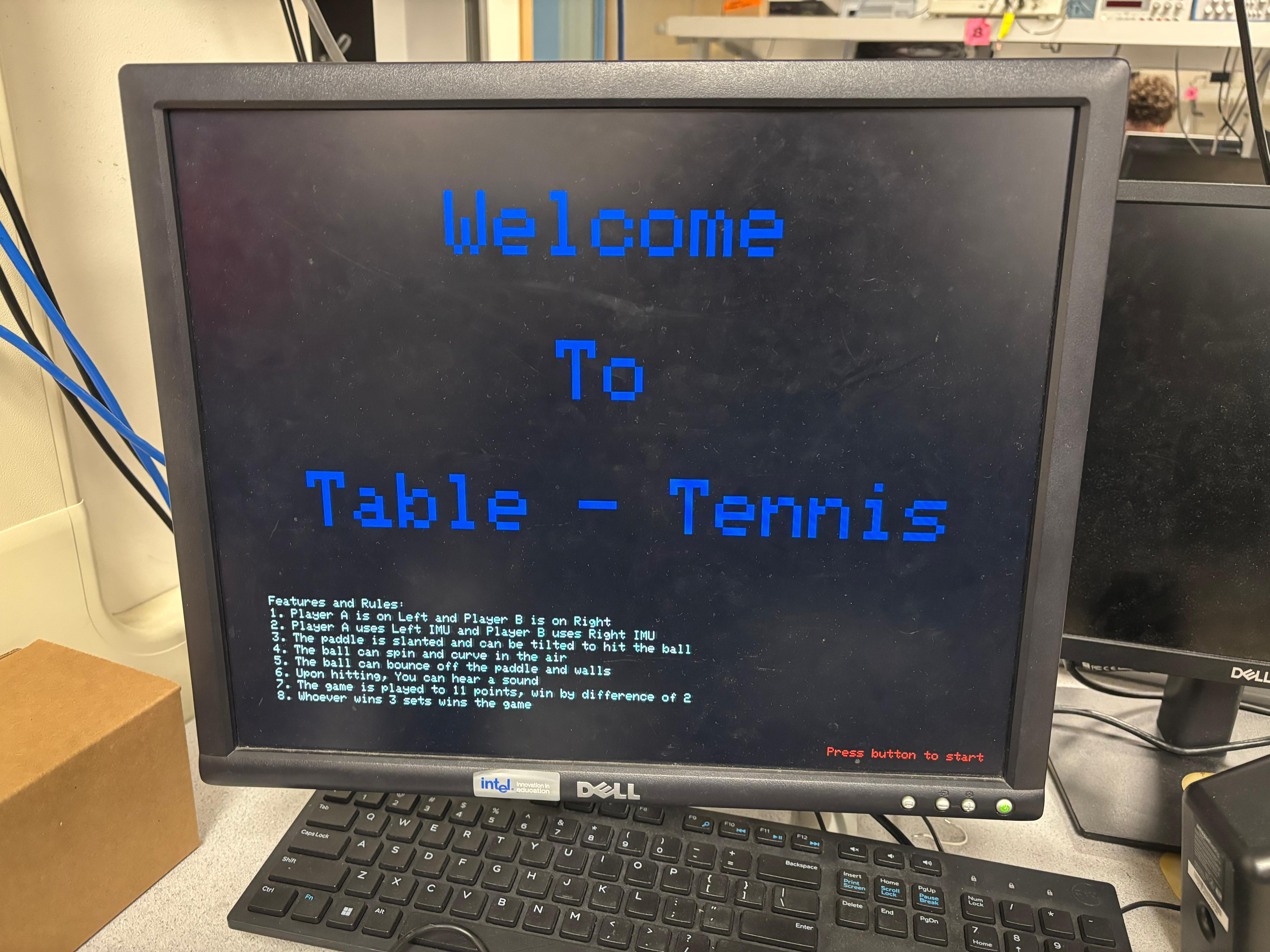
Fig [1]: Start screen with introductory text - Waits for a button press to start.
The display is cleared using fillRect, and a welcoming introduction screen is rendered via the writeString, setCursor, and setTextSize functions from the VGA graphics library. As shown in the first image, the screen prominently displays "Welcome to Table Tennis" in large blue letters centered on the screen. Below it, in small white text, are detailed game rules and features clearly instructing the players on control mechanisms, spin, audio feedback, and scoring.
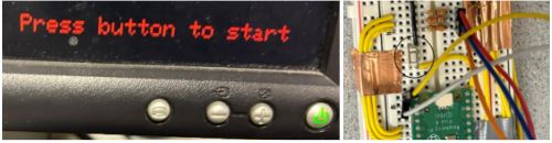
Fig [2]: Button to be pressed at the start of the game
At the bottom right, in red, the phrase "Press button to start" is displayed, indicating to the user how to initiate the game. The system enters a polling loop using gpio_get to wait for this button press. On detection of a press, the screen is cleared again, the IMUs are re-initialized with init_two_mpus(), and the game logic begins.
2. Game Loop
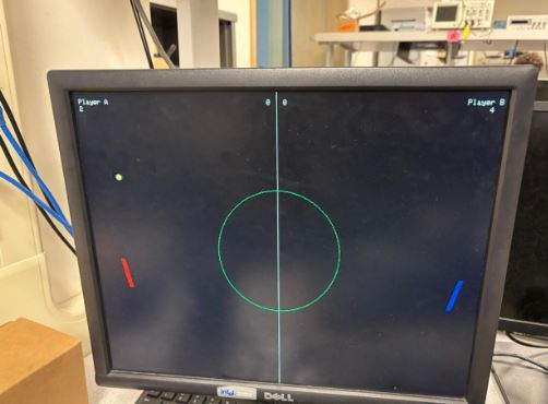
Fig [3]: Reads IMU data, updates paddle positions, checks ball collisions, updates display, triggers sound.
The game loop operates continuously after initialization and is managed within a Protothread running on core 0, which handles animation and gameplay. The main responsibilities of the game loop are to update ball and paddle positions, check for collisions, render graphics, manage scoring, and trigger sound feedback. Paddle positions are updated based on real-time IMU readings from core 1, which runs protothread_imus in parallel. This core separation ensures that heavy sensor polling does not interfere with time-sensitive VGA rendering. In each iteration of the loop, the ball is first erased using fillCircle in black, and its motion is calculated using wallsAndEdges(), which includes not only boundary collision detection but also Magnus force calculations from spin. After updating the ball’s position, it is redrawn, and the drawArena() function refreshes the game field, including the center line, circular field marking, and real-time scores. Paddle graphics are rendered using draw_paddles_core0(), which uses vector math to depict slanted paddles and draw_thick_line() for visual clarity.
3. Win Detection
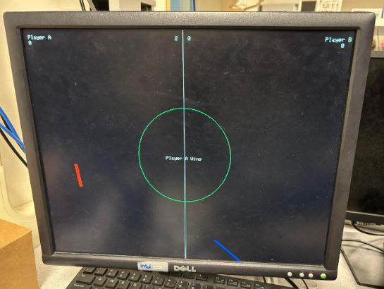
Fig [4]: Tracks score per round, checks if a player has won three rounds.
Scoring and win detection are managed in the calculateScore() function, which tracks each player’s point score (Score_A and Score_B) and round wins (WinningScore_A and WinningScore_B). A player must reach 11 points and lead by at least 2 points to win a set. This is validated through conditional checks on the score difference (diff1, diff2) and values. Upon winning a set, scores are reset, and the round counter for the winning player is incremented. If a player wins 3 sets, the game declares that player as the final winner by displaying either "Player A Wins" or "Player B Wins" using writeString at the center of the screen. The game is then paused briefly and reset using reset_board() and by spawning a new ball with spawnBoid().
4. Audio
Sound in the game is generated using DMA to offload audio playback from the main CPU. When the ball hits a paddle or a wall, the game logic in reflectBallFromPaddle() and wallsAndEdges() aborts and restarts DMA channels (dma_channel_abort, dma_start_channel_mask) to initiate sound playback from a pre-calculated sine wave table stored in DAC_data. The use of DMA ensures that sound is produced with minimal CPU intervention, allowing smooth and uninterrupted graphics and game logic processing. The audio adds immersive feedback, enhancing the physicality of the game.[4]
5. Game Reset
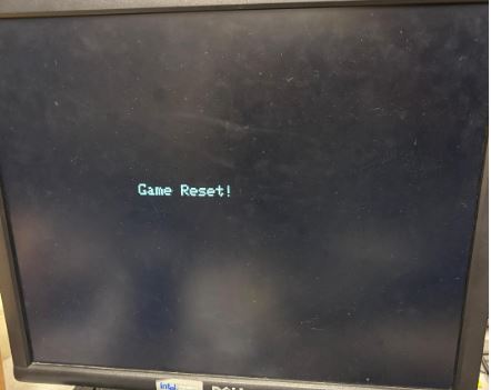
Fig [5]: Game resets on pressing the button during an ongoing game
After the first press of the start button, subsequent presses serve as a global reset trigger. This reset logic is handled with highest priority within the game loop in protothread_anim. If the button is detected as pressed (!gpio_get(15)), the entire game state is cleared: scores and round wins are reset to zero, the paddles are redrawn at initial positions, and a new ball is spawned. If this isn’t the very first start, a message "Game Reset!" is shown using writeString. This feature is critical for recovering from abnormal paddle behavior.
Program Design
The core of the software is built around four main components that work together to deliver a responsive and interactive gameplay experience. First, VGA graphics routines are used to render the entire display output, including the game field, paddles, ball, and user interface elements such as scores and messages. Second, audio feedback is implemented using DMA-driven playback routines, which allow sound to be triggered asynchronously whenever the ball hits a paddle or boundary, without burdening the CPU. Third, a custom game state manager oversees the overall game flow handling initialization, detecting button input to start or reset the game, managing the scoring system, and determining the win conditions. Lastly, the system incorporates real-time polling and data interpretation to control paddle movement, translating physical glove motions into smooth on-screen paddle responses through filtering and position mapping logic.
The VGA display is initialized using initVGA() and then used throughout the game to render graphics directly to the screen’s framebuffer. Drawing functions like fillRect, fillCircle, drawLine, and draw_thick_line are used to create static elements (arena lines, center circle) and dynamic elements (ball and paddle positions). Paddle rendering uses a thick line segment to represent a slanted paddle and is updated only when a change in position or tilt is detected to avoid flickering. Text rendering is managed using setCursor, setTextColor, and writeString, and numeric values are updated in place using fillRect to overwrite the old score values.
A key architectural decision was the division of labor between the two cores of the RP2040. Core 0 handles all graphics rendering and animation (ball physics, collisions, drawing, score updates). While Core 1 is exclusively responsible for reading and filtering IMU data, updating paddle positions, and calculating tilt.
This split allows for parallel execution and ensures that time-critical VGA drawing is not delayed by I2C communication or filtering computations. Shared state is managed carefully using a double-buffered paddleState[] structure and an activeBuffer variable to avoid concurrency issues. This design significantly improved performance and responsiveness.
An adaptive difficulty system is introduced where the ball speed, paddle size, or number of balls change based on the player's performance. This could help maintain balanced gameplay for users of varying skill levels.
Software Design
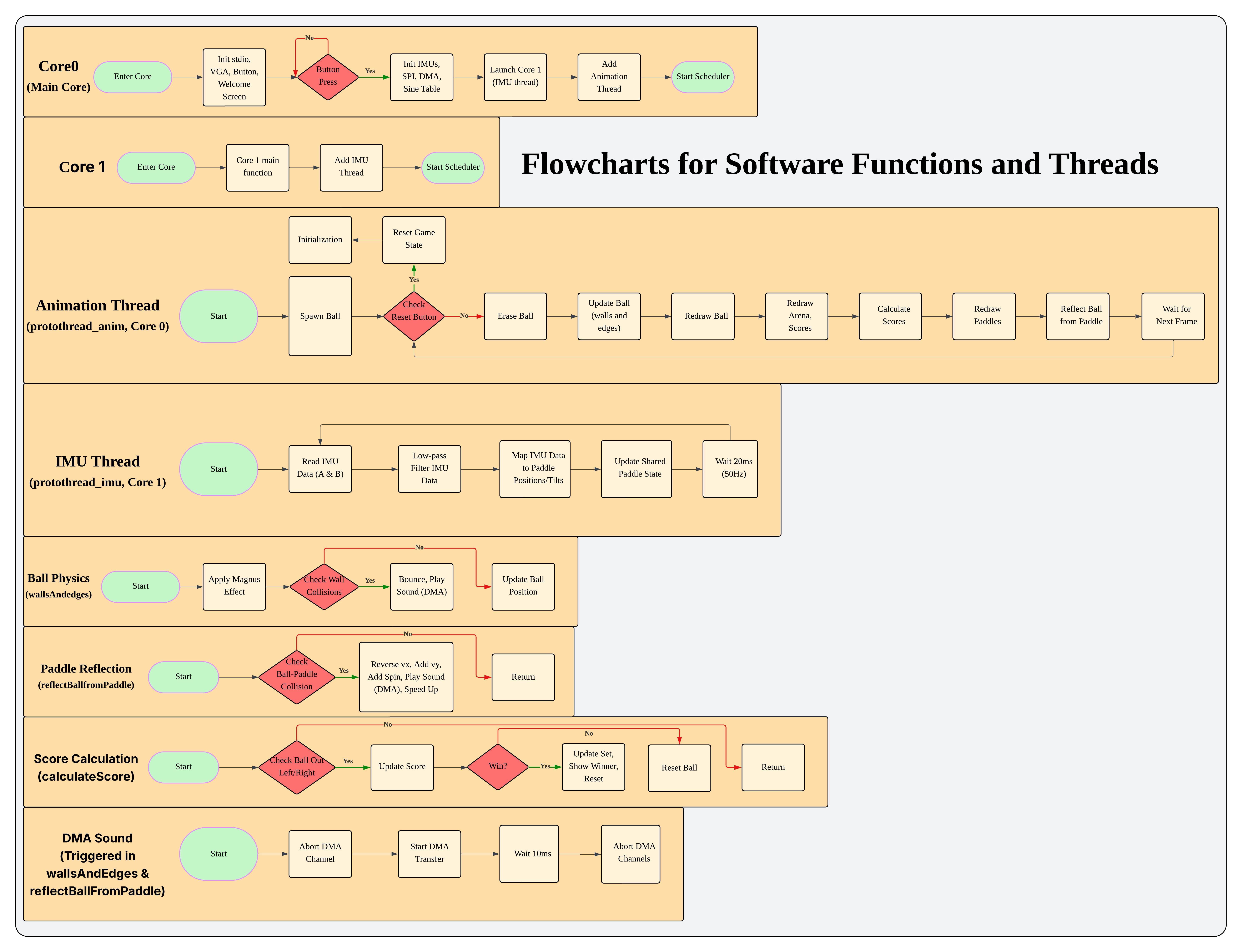
Fig [6]: Flowchart for Software Function and Threads
This flowchart provides a comprehensive breakdown of the multithreaded architecture used in the embedded ping-pong game system, running on dual cores. Core0 handles system initialization, peripheral setup, and launches Core1 and the animation thread. Core1 subsequently manages IMU data processing through a dedicated thread. The animation thread running on Core 0 governs the main game loop handling ball spawning, redrawing elements, collision detection, score calculation, and paddle reflection. Additional functions like Ball Physics, Paddle Reflection, Score Calculation, and DMA Sound operate asynchronously to manage game mechanics like Magnus effect, sound triggering, and score updates, ensuring modular, real-time execution.
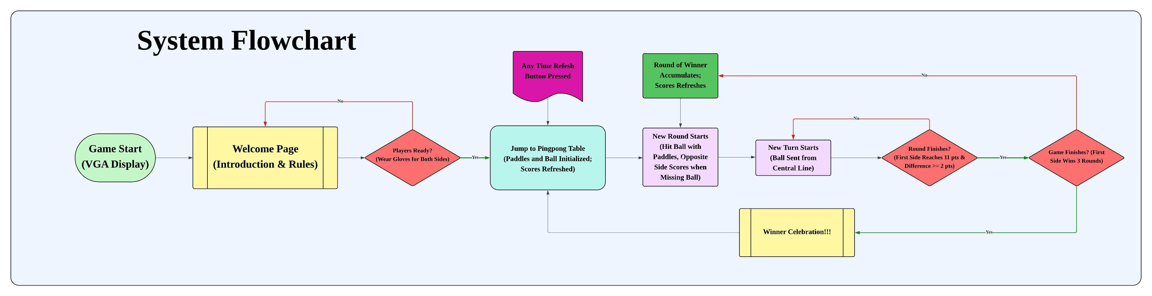
Fig [7]: System Flowchart
This high-level system flowchart outlines the user interaction and game progression logic on the VGA display. The flow begins with a welcome screen, prompting players to get ready (with gloves), followed by initiating the game table with paddles and ball setup. The game proceeds with successive rounds, updating scores when a player misses. A round concludes when a player scores 11 points with a 2-point lead, and the game ends when a side wins 3 rounds. The system also includes an interrupt mechanism to refresh the game at any point and culminates in a celebratory display upon determining the final winner.
Hardware Design
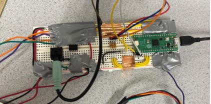
Fig [8]: Protoboard Connectivity
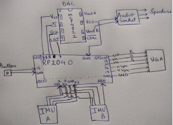
Fig [9]: Hardware Block Diagram
This hardware architecture balances performance, simplicity, and modularity, allowing the game to read both IMUs, render VGA graphics, and produce sound all from a single RP2040 chip. The hardware setup for the project involved careful synchronization of VGA signal timing with real-time game logic, along with stable interpretation of IMU data for smooth paddle control. Achieving jitter-free ball-paddle collisions required fine-tuning of low-pass filtering and precise bounding box calculations. The system is powered by a Raspberry Pi Pico (RP2040) microcontroller, with two 6-DOF IMU sensors mounted on gloves for motion-based input. A piezo speaker driven via DMA provides audio feedback, while a VGA screen at 640x480 resolution displays the game. A single push button serves as the game’s start and reset input.
| Component | RP2040 GPIO Pin(s) | Notes |
|---|---|---|
| IMU A | GPIO 2 (SDA), GPIO 3 (SCL), 3.3V, GND | I2C address 0x68 |
| IMU B | GPIO 2 (SDA), GPIO 3 (SCL), 3.3V, GND, AD0 = HIGH | I2C address 0x69 |
| Button | GPIO 15 | Pulled up internally, active LOW |
| DAC (Audio) | GPIO 5 (CS), GPIO 6 (SCK), GPIO 7 (MOSI), 3.3V, GND | SPI0-based DAC |
| VGA Output | GPIOs 16–21, GND | RGB + Sync signals, uses resistors |
| Shared 3.3V | VCC to DAC and both IMUs | Power supply |
| Shared GND | Common ground for all components |
Table [1]: Hardware Connections
The project uses a single Raspberry Pi Pico (RP2040) microcontroller to control the game logic, VGA rendering, IMU data acquisition, and sound generation. Two MPU6050 IMUs are connected to the same I2C bus, leveraging the I2C1 channel of the RP2040. Each MPU6050 has a configurable I2C address via the AD0 pin when this pin is tied LOW, the device address is 0x68, and when HIGH, the address is 0x69.
In our hardware setup, IMU A (Player A): AD0 is tied LOW, giving it the address 0x68, and IMU B (Player B): AD0 is tied HIGH, giving it the address 0x69. Both IMUs share the SDA and SCL lines, GPIO 2 (SDA) and GPIO 3 (SCL) of the Pico are used for I2C1 communication, 3.3V from the Pico powers both IMUs, and GND from the Pico is connected to both IMUs.
This means the first IMU (at 0x68) has 4 wires (VCC, GND, SDA, SCL), and the second (at 0x69) has 5 wires VCC, GND, SDA, SCL, and AD0 connected to 3.3V to set its address high. These connections allow both IMUs to operate on the same I2C channel while being independently addressable. [7]
A single push-button is used for two purposes: starting the game after the introduction screen and resetting the game at any point after the first start. The button is connected to GPIO 15 and configured as an active-low input. One side of the button connects to GND and the other side connects to GPIO 15. The internal pull-up resistor is enabled in software using gpio_pull_up(), which ensures the input is HIGH when not pressed and LOW when pressed. This simple configuration allows the firmware to continuously poll the button state using gpio_get() and respond to presses reliably.
Audio output is generated using a DAC (Digital-to-Analog Converter) connected via the SPI0 interface. This setup allows audio playback (sine wave tones) to be streamed efficiently using DMA, minimizing CPU load during sound output. The connections to the DAC are as follows:| RP2040 GPIO / Pin | Function | DAC Connection |
|---|---|---|
| GPIO 5 (Pin 7) | SPI0 CS (Chip Select) | CS |
| GPIO 6 (Pin 9) | SPI0 SCK (Clock) | SCK |
| GPIO 7 (Pin 10) | SPI0 MOSI (Data Out) | SDI |
| 3.3V (Pin 36) | Power Supply | VCC |
| GND (Pin 3) | Ground | GND |
Table [2]: DAC Connections with RP2040
This DAC is used to generate the sound effect played when the ball hits a paddle or the wall, using a precomputed sine wave table and streamed through SPI using DMA (dma_channel_configure, dma_start_channel_mask).
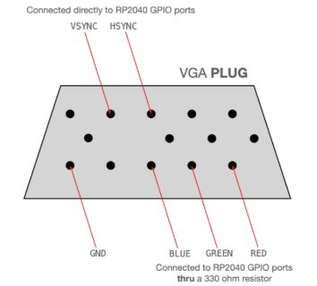
Fig [10]: VGA Connection to RP2040 [3]
Video output is driven directly from the Raspberry Pi Pico using bit-banged VGA signals on dedicated GPIO pins, only 6 connections are required to create a working VGA signal:
These connections are used to generate a 640x480 60Hz analog VGA signal, which is rendered with game graphics using custom drawing routines (fillCircle, draw_thick_line, writeString, etc.). The dual green resistors help with brightness modulation for that channel.
| RP2040 GPIO | Function | VGA Connection |
|---|---|---|
| GPIO 16 | Horizontal Sync | HSync |
| GPIO 17 | Vertical Sync | VSync |
| GPIO 19 | Video Signal (via 330Ω) | Green |
| GPIO 20 | Video Signal (via 330Ω) | Blue |
| GPIO 21 | Video Signal (via 330Ω) | Red |
| GND | Ground | VGA Ground |
Table [3]: VGA COnnection with RP2040
These connections are used to generate a 640x480 60Hz analog VGA signal, which is rendered with game graphics using custom drawing routines (fillCircle, draw_thick_line, writeString, etc.). The dual green resistors help with brightness modulation for that channel.
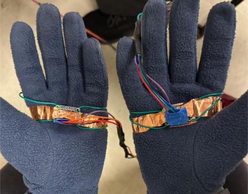
Fig [11]: IMU mounted on the glove for the player
To enable intuitive, gesture-based control of the paddles, each MPU6050 IMU was securely mounted onto a glove, one for each player. The IMUs were positioned on the back side of the hand near the wrist, which allowed them to capture tilt and motion data effectively without being obstructed by finger movements. To ensure a firm attachment, each IMU module was wrapped in copper tape to maintain a stable surface against the glove fabric. The modules were then firmly taped onto the gloves using insulating electrical tape, ensuring that the sensors did not shift during gameplay. To route the electrical connections back to the microcontroller, color-coded jumper wires were soldered to the IMU breakout boards. These wires were carefully secured along the wrist and arm area of the glove using heat shrink tubing and additional tape. This reinforcement minimized mechanical stress on the solder joints and prevented wire movement from interfering with sensor readings. The careful mounting and wiring ensured stable data reading, comfortable wearability, and consistent paddle control throughout the game.
The VGA signal generation code was based on open-source VGA libraries tailored for RP2040 microcontrollers. The audio output method using DMA was adapted from public RP2040 sound examples. We modified them significantly to support real-time game triggering and frequency customization.
Problems Faced and Resolutions
- Low Pass Filtering IMU data was initially too jittery, causing erratic paddle motion. We applied low-pass filtering with a small alpha coefficient to smooth the values. This ensured that recent values were weighted less heavily, resulting in fluid motion.
- Paddle Clamping: At first, paddles could move beyond the screen or into the opponent’s territory. We resolved this using clamp() functions to constrain x and y positions within their respective allowable regions (XA_RANGE, XB_MIN, Y_RANGE).
- Color Confusion:Initially, both paddles were rendered in the same color, leading to player confusion. To enhance clarity, Player A’s paddle was rendered in red, and Player B’s paddle in blue.
- IMU Interference: The physical movement of wires between the two IMUs was causing interference, where moving one glove could affect the other paddle. We solved this by using heat-shrink tubing to isolate wiring and reduce unwanted mechanical coupling.
- Loose Connections: Solder joints on IMUs were occasionally loose, leading to frozen paddle inputs while the ball continues moving. To quickly recover from such cases, we emphasized the reset button functionality, which completely initialized the IMUs and game state.
- Paddle Graphics: Initial attempts to use fillRect didn't resolved our issue if we want some tilt motion. Ultimately, we used draw_thick_line() which contains drawline() which rendered clear and dynamic slanted paddles with a given thickness declared in Paddle_Thickness Variable.
Results
The final implementation of the glove-controlled table tennis game produced successful results in terms of functionality, responsiveness, and user experience. The VGA display output was stable, and the graphical elements such as the paddles, ball, score, and arena were rendered without visual flicker or tearing. The system maintained a steady frame rate of approximately 30 frames per second, with minimal latency in paddle movement, ensuring a smooth and interactive gameplay experience. The use of DMA for audio playback significantly improved concurrency, allowing the system to handle audio triggers without blocking or delaying video rendering and IMU updates. This ensured that the game remained responsive even during high-action scenarios with frequent paddle-ball interactions.
| Constant | Purpose | Value (approx.) |
|---|---|---|
| magnusK | Magnus force coefficient | 0.03 (Q15) |
| spinDecay | Spin decay factor per frame | 0.995 (Q15) |
| alpha | Paddle motion to spin scaling | 0.125 (1/8) |
| beta | Paddle velocity to spin scaling | 0.25 (1/4) |
Table [4]: Final Values used for the Code
In terms of accuracy, the paddle collision detection was reliable and precise, with a positional tolerance of about 2 pixels, making gameplay fair and consistent. At times the paddle would freeze and the animation would continue, this would be due to loose contact, when this happens on pressing the reset button, the game resumes from the start. The audio waveform generated via DMA and SPI closely matched the intended sine wave, with test measurements confirming frequency accuracy within ±3 Hz around the 500 Hz target. Video signal timing was carefully managed through the VGA libraries, and oscilloscope verification confirmed the correct synchronization of horizontal and vertical sync pulses, ensuring compatibility with standard VGA monitors.
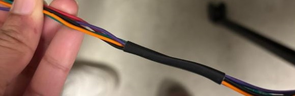
Fig [12]: Heat Shrink used as Safety measure
Safety considerations were also addressed in the hardware design. All components were powered through the RP2040’s regulated 3.3V rail to prevent overvoltage. The IMUs were mounted securely on gloves, and all wiring was insulated and reinforced using heat shrink tubing to prevent accidental disconnections or shorts during gameplay. The pushbutton reset functionality allowed quick recovery in the rare event of a sensor freeze or signal loss, maintaining a safe and recoverable environment.
In terms of usability, the system was intuitive and enjoyable to use. Players could control paddles naturally with glove motion, and the visual and audio feedback helped them quickly adapt to the control scheme. The instructions displayed on the start screen made the game accessible to new users without prior explanation. Multiple individuals tested the game and found it responsive, engaging, and easy to operate, validating the system’s robustness and design reliability across a variety of users. Overall, the design met and exceeded performance expectations in all key functional areas.
Conclusion
The project successfully achieved its intended goals of developing an immersive, real-time table tennis game that integrates gesture-based control, VGA graphics, and DMA-driven audio feedback, all running on a resource-constrained Raspberry Pi Pico microcontroller. By leveraging IMUs mounted on gloves, the design allowed players to control paddles through natural hand motions, bringing a physical and intuitive element to what is traditionally a keyboard-based or joystick-based interface. The game ran at a consistent 30 frames per second, with smooth paddle tracking, low latency, and accurate collision physics including spin dynamics using the Magnus effect.
From a standards perspective, the design adhered to established protocols and electrical signaling formats. The VGA output was generated following RS170-compatible video timing, ensuring compatibility with standard displays, while I2C and SPI protocols were used to interface with IMUs and the DAC, respectively. Throughout the project, we made use of publicly available and open-source code, including VGA timing libraries and SPI/DMA audio playback routines. The design was entirely built on documented, open technologies, making it reproducible and extensible for others.
While the current implementation is relatively simple, the use of IMU-driven glove controls in a VGA game setting opens the door to future innovations. There may be opportunities to patent more advanced gesture-based gaming interfaces or adapt the system for educational applications. If we were to revisit the project, potential improvements could include wireless IMUs for untethered play, expanded gameplay modes, or machine learning-based motion interpretation. Overall, the project serves as a strong proof of concept and an exciting demonstration of what is possible with microcontrollers and creative human-computer interaction design.
Future Work
While the current implementation of the glove-controlled table tennis game provides an engaging and responsive two-player experience, there are several promising directions for future enhancement and development:
- Multiple Ball Gameplay: Introducing multiple balls in play could significantly increase the challenge and excitement of the game. This would require adjustments in collision detection logic, rendering multiple ball objects, and managing independent ball velocities and spin. Such a feature could be implemented using additional structures for ball states and integrated into the existing core 0 animation thread.
- Single-Player Mode with AI: Implementing a computer-controlled paddle would allow solo gameplay. A basic AI could follow the ball’s trajectory using predictive movement, while a more advanced version could incorporate machine learning models to simulate human-like behavior.
- Wireless IMU Gloves: Currently, the gloves are wired to the system, which may restrict player mobility. Future iterations could integrate wireless microcontrollers like ESP32s on each glove, transmitting IMU data via Bluetooth or Wi-Fi to the RP2040.
- More Detailed Paddle Control: Incorporating additional gesture recognition, such as twisting the wrist to apply more spin or angle, could give players more nuanced control of the paddle, simulating advanced table tennis techniques.
- Networked Multiplayer: Expanding the system to allow online multiplayer over Wi-Fi could make the game more accessible and competitive. This would involve synchronizing game states between multiple devices over a network connection.
- Touchscreen or Keyboard Menu Interface: Adding a small touchscreen or keyboard interface could allow players to select game modes, difficulty, or colors before starting, creating a more user-friendly experience.
Team Members and Work Distribution
The development of this glove-controlled table tennis game was a collaborative effort by a team of three members, each contributing unique skills while also working collectively on core aspects of the project. All team members were jointly involved in conceptualizing the original game idea, outlining the project proposal, and formulating the logical flow of the game, including how gesture control, VGA graphics, and sound integration would work together cohesively.
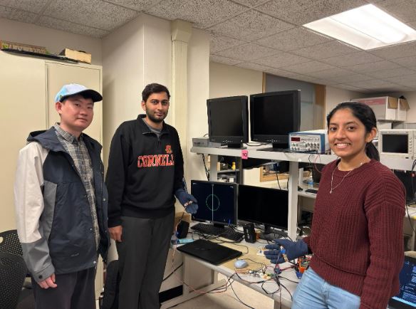
Fig [13]: Picture of the Team with the Working Setup
The software development was primarily handled by hp475, who took lead on writing the core game logic, implementing the animation threads, integrating the paddle control algorithms, and managing the scoring and win conditions. The audio system, including DMA-based sound triggering and SPI communication with the DAC, was designed and implemented by zf248, who ensured smooth real-time audio playback without interrupting gameplay. asm367 was responsible for the hardware implementation, including breadboarding, soldering all connections between the Pico, DAC, VGA, and IMUs, and adding heat shrink tubing to stabilize the IMU wires and reduce interference between player inputs. All three team members were actively engaged in documentation, testing, and debugging throughout the development process. They collaborated closely to refine the paddle responsiveness, eliminate cross-interference between IMUs, and tune the system for smooth gameplay.