Introduction
Audio capture using laser-reflected surface vibrations - no contact, no mic, just light.
Abstract
This project demonstrates the feasibility of an optical microphone system that captures sound through vibrations detected by a reflected laser beam. By aiming a laser diode at a vibrating reflective surface and measuring fluctuations in the reflected light intensity using a photodiode, we convert mechanical vibrations caused by sound into electrical signals. These signals are filtered, digitized, processed, and ultimately played back through a speaker. Our implementation includes both analog and digital signal processing on a Raspberry Pi Pico microcontroller. The final system reliably reproduces audio and demonstrates how light can be used to perceive sound, with performance evaluated across varying distances using signal-to-noise ratio (SNR) measurements.
We chose to pursue this project because we were intrigued by the idea of non-contact sound detection using light, a technology that has been used in espionage and surveillance for decades. The concept of "hearing through walls" using only a laser beam and a sensor was both technically challenging and intellectually stimulating. By building an optical microphone, we hoped to gain a deeper understanding of analog and digital signal processing, optics, and real-world system integration. This project also presented an opportunity to explore the intersection of electronics, acoustics, and photonics in a novel application.
High Level Design
The design of our optical microphone system is rooted in the fundamental physics of wave propagation, photodetection, and analog signal processing. The core idea, to detect sound remotely via laser reflection, draws inspiration from historical espionage techniques and more recent DIY laser microphone builds, such as those popularized in the video “I Built a CIA Spy Device (Laser Mic)” (2025).1
At a high level, the system operates by converting sound-induced surface vibrations into light intensity modulations, which are then transduced by a photodiode into voltage signals. These signals undergo analog conditioning (amplification, filtering, biasing) before being digitized by the Raspberry Pi Pico, processed, and converted back to analog audio for playback.
Using off-the-shelf components kept the design cost-effective while ensuring performance. While we did not find active patents blocking educational prototyping of optical microphones, commercial systems exist,2 and copyright protections may apply to proprietary implementations. However, our system remains open-source and educational in nature, with all components, code, and designs based on publicly available principles and datasheets.
Concepts
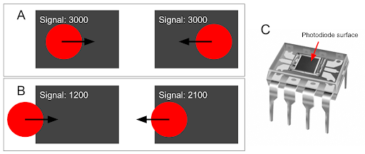
This project focuses on building a low-cost, portable optical microphone system. Unlike traditional microphones that directly detect sound pressure, an optical microphone leverages the principle that sound waves cause small but detectable vibrations in objects. When a laser beam reflects off such a vibrating surface, the intensity and direction of the reflected beam change subtly. A photodiode detects these changes, which can be translated back into sound via signal processing. The alignment of the beam to the photodiode is extremely important for this change to be detected. The focus of the beam should only be on half of the photodiode’s surface for effective detection of change as illustrated in Figure 1. Specifically, we used the OPT101 that has a flat rectangular surface as its receiver.
A vibrating surface modulates the phase and angle of the reflected laser light. This modulation alters the intensity captured by the photodiode due to the beam's displacement over its active area. These fluctuations are converted to voltage, passed through analog filters to remove noise, digitized, processed with filtering and then converted back to analog audio signals for playback.
Design and Testing
Hardware Description
The following table lists all components used in this project including a short description, source, and cost of materials.
| Component | Description | Source | Cost ($) |
|---|---|---|---|
| OPT101 | Monolithic photodiode and transimpedance amplifier | Amazon | 22.72 |
| Laser Diode | Class II laser for safe optical transmission | Amazon | 13.97 |
| LM358P | Operational amplifiers for analog filtering | Lab supply | 0.00 |
| Resistors & Capacitors | For analog circuitry | Lab supply | 0.00 |
| MCP4822 | Digital-to-Analog Converter | Lab supply | 0.00 |
| TLE2426CP | Rail splitter to create virtual ground | DigiKey | 2.67 |
| Speaker & Audio Jack | Output for sound | Lab supply | 0.00 |
| Pi Pico | Microcontroller handling signal acquisition and processing | Provided | 0.00 |
| Reflective Surface | Thin plastic window mounted on a box | UPS Store/Custom | 3.50 |
| Helping Hands | Small metal stand with clips to mount laser diode and OPT101 | Amazon | 9.99 |
| TOTAL | 52.85 | ||
Mechanical Setup
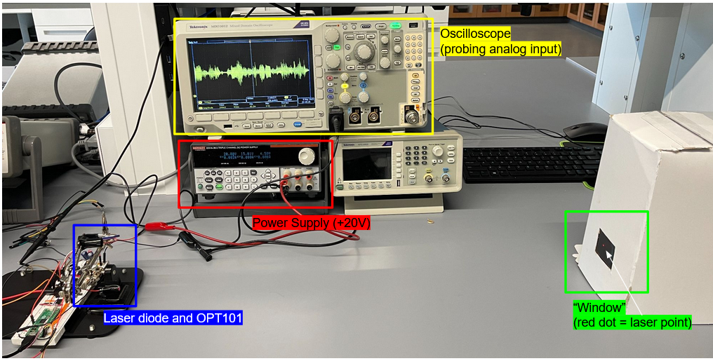
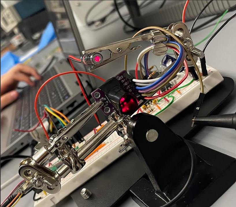
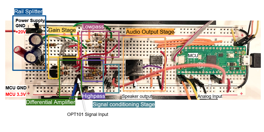
Figure 2 illustrates the optical alignment setup, designed to maximize signal fidelity and reduce interference during operation. In our configuration, the laser diode was positioned to direct a coherent beam toward a reflective surface mounted within a thin cardboard enclosure. The reflected beam was then directed onto the active region of the OPT101 photodiode. To ensure optimal alignment, both the laser and photodiode were mounted on adjustable stands, allowing for fine-tuned angular and positional control. The breadboard containing the analog circuitry was also stationed on top of the black mounting surface to prevent unintended movements from all the jumper wires.
Alignment
The cardboard enclosure was custom made and consists of an envelope and cut out plastic piece from a plastic container. Chosen based on experimentation, the integrity of the plastic cut out offered better signal fidelity than other materials like aluminum foil due to consistent reflectivity and minimal distortion. It also replicated reflecting off an actual window. Foil, while shiny, introduced unpredictable refraction and was prone to crinkling, which distorted the laser reflection. In contrast, the thin plastic sheet provided a stable, smooth surface that yielded significantly clearer and more consistent audio signals due to its surface uniformity and rigidity. This choice allowed for facilitated alignment.
To further improve signal quality and minimize noise, the photodiode was encased in a custom-made black tube constructed from matte black tape. This improvised light shield served a crucial function: it blocked ambient light from surrounding sources, such as overhead fluorescent lights or sunlight from windows, which could otherwise saturate or distort the photodiode’s output. Without this shielding, the OPT101 would often saturate when exposed to strong ambient light, rendering it unable to detect subtle fluctuations in laser intensity caused by surface vibrations.
By narrowing the photodiode’s field of view to accept only the focused reflection from the laser, the black tube helped isolate the desired signal and significantly improved the signal-to-noise ratio (SNR) of our measurements. This setup ensured that the variations in photodiode output were due to the modulated reflected laser light alone, preserving the integrity of the vibration-induced signal and enabling reliable downstream audio reconstruction.
Electrical Setup
The Raspberry Pi Pico was used as the central microcontroller for its fast processing capabilities, built-in 12-bit ADC, and precise timing control using hardware interrupts. It enabled real-time sampling of the photodiode signal, performed digital signal processing, and interfaced seamlessly with the DAC for audio playback, all while maintaining a low-cost and compact footprint.
Laser DiodeWe used a laser diode because it provides a coherent, narrow beam ideal for accurately reflecting off vibrating surfaces. A consistent, high-intensity beam ensures that small changes in angle or surface displacement result in measurable variations in the detected signal. The cathode is connected to ground and anode is connected to 3.3V of the Pi Pico.
OPT101 PhotodiodePhotodiodes convert light fluctuations to voltage. The OPT101 was selected for its simplicity and precision. It combines a photodiode and a high-gain amplifier in one 8-pin package, minimizing the need for external components. Its analog output responds proportionally to incident light, which is essential for detecting subtle intensity changes due to vibration-modulated reflection
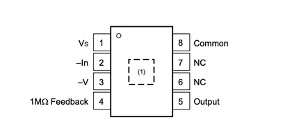
For proper operation, the power (pin 1, Vs) is set to 3.3 V from the Pi Pico relative to the most negative supply (pin 3, -V), which is connected to the ground of the Pico. The output voltage corresponding to the photodiode signal is available at pin 5 (Output) with pin 4 (1 MΩ Feedback). Pin 2 (-In) and pin 8 (Common) are connected to ground. This pin configuration supports straightforward integration into analog circuits, allowing precise detection of light intensity with minimal external components.
Rail SplitterThe TLE2426CP chip is used to create a virtual ground that is in the midpoint of a voltage supply to be used by all op amps.
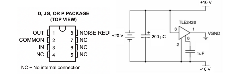
VGND, or virtual ground, is a midpoint voltage reference used in single-supply analog circuits to enable full-range AC signal processing. Since our system operates on a single positive voltage supply (0 to +20V), traditional op-amp circuits that expect both positive and negative rails would not function correctly without a reference halfway between. The TLE2426CP rail splitter generates this mid-supply voltage (+10V from a 0-20V supply), which we define as VGND. This allows the analog signal to swing both above and below this reference point while staying within the supply range. VGND is critical for correctly biasing op-amps in the signal chain and maintaining symmetrical signal processing without the need for dual power supplies.
Analog filteringWe weighed hardware/software trade offs carefully. While signal filtering could be done digitally, analog pre-filtering is essential to prevent aliasing and saturation in the microcontroller’s ADC. Note that all operational amplifiers used are LM358P, powered at +10V and -10V from the split rails.
Differential Amplifier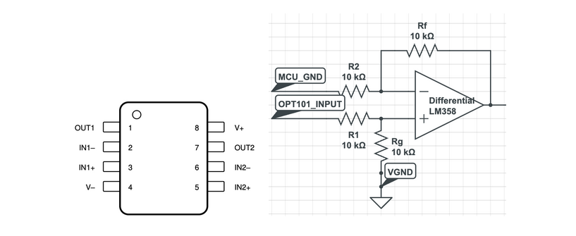
To ensure consistent signal referencing and compatibility between the OPT101 photodiode output and the analog filter stages, we employed a differential amplifier circuit using the LM358P operational amplifier. This configuration is critical because the OPT101 and the analog signal chain operate with different ground references, specifically, the OPT101 is referenced to the microcontroller's ground (MCU_GND), while the analog filters are referenced to a virtual ground (VGND) created by the TLE2426 rail splitter. The differential amplifier subtracts V2 from V1 and realigns the OPT101 output voltage to the analog domain’s VGND reference. All resistor values (R1, R2, Rf, and Rg) are chosen as 10 kΩ, ensuring a unity gain configuration where the output voltage equals the difference between V1 and V2 (OPT101 signal and MCU_GND) but now referenced to VGND.
Bandpass Filter (100 Hz – 1 kHz)This stage acts to attenuate frequencies outside of speech range, below 100 Hz and above 1 kHz. This frequency range was selected to isolate the most informative and energy-dense components of typical audio content, especially human speech and lower musical tones. Frequencies below 100 Hz are often dominated by environmental noise (building vibrations, air conditioning rumble) and 60 Hz power line hum. Frequencies above 1 kHz include sibilants and high harmonics, but are more susceptible to distortion, ambient noise, and laser beam alignment imperfections. Our laser setup prioritized reliable low-frequency capture over full-spectrum fidelity.
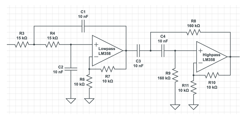
The gain from the active low pass filter is Amax = 1 + R₆ / R₇. We desired a gain of 2, so we chose resistor values R₆ = R₇ = 10kΩ.
We can calculate the low pass cut-off frequency with:
fc = 1 / (2π √(C₁ · C₂ · R₃ · R₄))
For a cut-off frequency of 1061 Hz, we choose resistor values R₃ = R₄ = 15kΩ and capacitor values C₁ = C₂ = 10nF.
The gain for a second order active high pass filter is Amax = 1 + R₁₁ / R₁₀. For a gain of 2, we choose the resistor values R₁₁ = R₁₀ = 10kΩ.
The cutoff frequency for the high pass circuit is:
fc = 1 / (2π √(R₃ · R₄ · C₁ · C₂))
For a cutoff frequency of 99 Hz, we choose resistor values R₃ = R₄ = 160kΩ and capacitor values C₁ = C₂ = 10nF.
Adjustable Gain Stage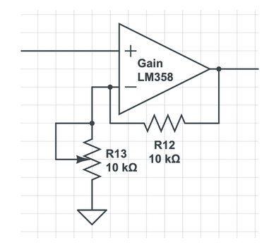
The gain for the non-inverting amplifier circuit is Amax = R₁₃ / R₁₂, where R₁₂ = 10kΩ.
The gain from the circuit is controlled via a potentiometer for signal amplification, as R₁₃ is a 10kΩ thumb potentiometer that can be rotated to a higher value.
This is useful for tuning the signal so that the final output signal is of good integrity.
Signal ConditioningSince the Raspberry Pi Pico’s analog-to-digital converter (ADC) can only accept voltages in the 0 to 3.3V range, the input signal must be properly biased and protected to ensure safe and accurate sampling.
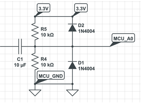
After analog filtering and amplification, the audio signal still contains both positive and negative components relative to the analog ground (VGND). However, the Pi Pico’s ADC cannot interpret negative voltages and could be damaged if such signals are applied. To address this, a DC biasing circuit is used to shift the entire signal upward, centering it at 1.65V.
In addition to biasing, it is essential to protect the Pi Pico’s ADC input from unexpected voltage spikes that may result from noise, misalignment, or signal overshoot. To accomplish this, we implemented a voltage clamp diode circuit at the input pin. If the signal exceeds 3.3V, the upper diode becomes forward-biased and safely diverts excess current to the 3.3V rail; if the signal drops below 0V, the lower diode activates and routes current to ground. This mechanism prevents damaging voltages from reaching the sensitive ADC input, ensuring long-term reliability of the microcontroller.
Audio OutputThe MCP4822 Digital-to-Analog Converter (DAC) was used to convert the digitally processed audio signal from the Pi Pico back into an analog voltage waveform suitable for audio playback. This setup follows the same configuration used in Lab 1, where the DAC is connected and communicates with the Pi Pico via SPI (Serial Peripheral Interface).6 After the signal is sampled from the OPT101, processed through digital filtering and optional gain/shift adjustments, the Pi Pico transmits the resulting digital values to the MCP4822. The DAC then reconstructs the analog waveform, which is fed into a standard 3.5 mm audio jack connected to a speaker. This stage completes the end-to-end audio pipeline, allowing users to hear sound originally transmitted through optical vibrations. The MCP4822’s high resolution (12-bit) ensures smooth and continuous signal reconstruction, minimizing distortion and noise in the final audio output.
Software Description
Our software architecture is nearly entirely interrupt-driven with a serial thread that allows for acoustic adjustments.
Digital Signal Conditioning
Depending on the laser alignment, we typically need an additional linear transformation to make the analog sample readings interpretable. For example, typical readings from the Pi-Pico after signal condition would be 1987, 1995, 2001, … .
Passing these values directly to the 12-bit digital-analog-converter results in a low-varying high pitched sound. We observe that this is because the relative difference between values is small.
We adjust for this by taking the running minimum/average of some number of samples and applying a vertical shift on incoming values by this minimum/average.
Afterwards, we can optionally exaggerate the differences between values by scaling by some fixed value as well. We find that although a large gain value can increase the sound of the acoustics we want to capture, it also increases the effect of hissing and white noise. Surprisingly, we found that although a smaller gain value decreased the sound of the acoustics we wanted to capture, it improved the fidelity of it. We find in general a shift value of -1980 and a gain value of 0.8 worked well in most situations.
Finite-Impulse-Response Filter
Interrupt SamplingWe initialize an alarm interrupt service routine at 50 kHz. This implies that we have a timing constraint of 20 microseconds.
In addition to shifting and gaining, we also employed a finite-impulse-response filter to low-pass the signal before feeding it into the DAC. To meet the timing constraints of our interrupt response filter, we use a five tap FIR filter (0.2, 0.2, 0.2, 0.2).
Intuitively, this filter acts as a low-pass filter because low frequency components “show up” more often in the FIR filter than high frequency components. Since we take the average of the last five samples, low frequency components have more weight and contribute more to the output signal.
Other MethodsWe briefly explain other potential methods for digital signal processing and their disadvantages. First, recall that our timing constraint is 20 microseconds. We briefly experimented with fast-fourier-transforms and inverse-fourier-transforms, but these approaches were too slow, even with fixed-point optimizations and overclocking. We also briefly experimented with 2-pole infinite-impulse-response filters, but they gave little qualitative improvement over the FIR filter that we settled with.
Results
Qualitative Analysis
Listener Identification Testing
To qualitatively assess the perceptual clarity and recognizability of the audio captured through our optical microphone, we conducted a user-based evaluation. Our goal was to determine whether human listeners could discern audio content reliably and distinguish between periods of signal and silence based solely on laser beam reflection. This helped validate not just signal acquisition, but meaningful audio reconstruction.
Participants were provided with over-ear headphones connected to the output of our optical microphone system. Inside the envelope enclosure, music was played using a speaker. The laser beam was directed at the reflective surface about 2 ft away, and the reflected light was captured by the OPT101 photodiode. To isolate the effect of the laser-based signal transmission, we performed controlled "on/off" trials by manually blocking and unblocking the laser beam with a hand. When blocked, the system captured no signal and when unblocked, the system reconstructed the reflected vibrations into audible audio. This clear binary modulation served to highlight the laser’s role in transmitting the audio data.
Each listener was asked to:
- Indicate when they heard music and when the signal dropped out.
- Guess which song was playing based on the audio reconstructed through the system.
The laser beam was intermittently blocked (typically 5 - 10 seconds at a time) without notifying the listener when the change would occur. Each participant experienced multiple cycles of "music" and "no music" phases. All participants (n=9) correctly identified transitions between "music" and "no music" in real time. This confirmed that signal integrity was sufficiently high for listeners to distinguish between active and inactive transmission states. This increased confidence in transmission of signal and detection accuracy. The hand-blocking test reinforced the fact that the system was not passively picking up sound through air or structure-borne vibrations. Listeners could clearly detect the moment when the laser was interrupted, affirming that the audio output was driven exclusively by the reflected optical signal.
A range of music from pop music (BIRDS OF A FEATHER by Billie Eilish, Mirrors by Justin Timberlake) to classical pieces (The Swan by Saint-Saens, Violin Concerto No.1 by Tchaikovsky) was played for each participant. Approximately 88% of participants (8 out of 9) were able to correctly guess the song playing. This suggests that the fidelity of the reconstructed signal was high enough to preserve musical features such as rhythm, melody, and vocal tone. The person who was not able to recognize a clear song claimed they heard a lot of echo and loud sharp noises. This may have been due to the experiment being held during a lab time when many groups were talking and laughing during the experiment. The clutter of outside noise surrounding the reflective surface may have contributed to disruptive noise in the audio output.
Overall, participants described the audio as "muffled but recognizable," "slight static noise but clearly musical." Some participants described the bass sound as “super super clear” and were “very impressed by how the blocking of the laser really differentiated the on or off.” These subjective comments supported our measurements of signal clarity at close range.
This user-centered testing provided critical evidence that the system does not function as a traditional microphone and relies on the uninterrupted optical path. The output was intelligible and sufficiently clear for song recognition.
Quantitative Analysis
SNR
To quantify the effectiveness of our optical microphone system, we closely analyzed the signal-to-noise ratio (SNR) across different conditions using an oscilloscope. SNR served as a key metric in differentiating clean, usable signals from noise-dominated outputs. Oscilloscope measurements were taken at the analog input to the Pi Pico.
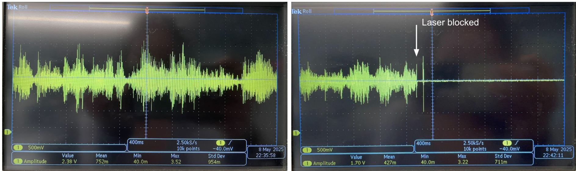
In well-aligned setups with proper shielding, SNR consistently exceeded 20 dB. Figure 11 displays representative oscilloscope traces taken during audio transmission with a clear signal and during a period of silence when the laser was intentionally blocked. In this case, the amplitude of the noise (when music was turned off or laser blocked) was consistently below 80 mV and the amplitude of the signal ranges around 2 V, depending on the part of the song. This calculates to a SNR of about 28 dB.
SNR (dB) = 20 log10(Signal / Noise) = 20 log10(2 / 0.08) = 28 dB
The speaker in the cardboard encasement was playing music at volume around 30 dB (whispering level). Notably, while the enclosure was thin and made of cardboard, it effectively attenuated audible sound to the outside. This meant that while the sound could not be heard by ear from outside the box, the laser still reliably picked up micro-vibrations on the reflective plastic sheet inside, confirming the high sensitivity of our optical pathway.
Note for demos: This is a video recording of the speaker output. The actual audio quality is significantly clearer when listened to directly through headphones, as the recording process introduces additional noise and distortion not present in the original signal.
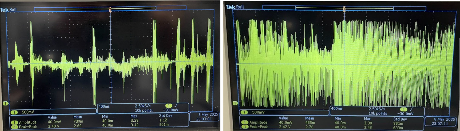
Notably, saturation frequently occurred during sections of music with strong bass. This is likely due to the fact that low-frequency sounds such as bass notes produce larger physical displacements in the vibrating surface. These displacements cause greater modulation in the reflected laser beam's angle and intensity, which in turn results in larger voltage fluctuations at the photodiode output.
We also observed that increasing the audio volume beyond the “whispering” level led to larger signal excursions. While this generally improved SNR and signal clarity, it also introduced the risk of voltage saturation. Since the analog front-end and the Raspberry Pi Pico ADC are constrained to a 0 - 3.3V range, excessive signal amplitude clipped at the rails, especially after amplification stages. Clipping was particularly noticeable during peaks in musical passages or speech when volume exceeded ~60 dB. Saturated signals resulted in distorted, static output and diminished audio integrity.
To mitigate this, gain stages were carefully tuned using a potentiometer, ensuring that signals stayed within an optimal amplitude window, large enough to rise above the noise floor, but small enough to avoid clipping. This gain-tuning, combined with SNR-based thresholding, was critical for establishing operating conditions that preserved signal fidelity.
Distance Testing
To further quantitatively evaluate the performance of our optical microphone system, we conducted a series of tests at varying distances between the reflective surface and the photodiode. Our goal was to determine how distance, environmental conditions, and material properties affect audio clarity and signal reliability.
The laser diode and OPT101 was kept fixed and re-aligned with the reflective surface, while the cardboard box was positioned to receive the beam at various distances: 1 ft, 2 ft, 3 ft, and 4 ft. For each configuration, the same piece of music at the same volume was played inside the enclosure. Signal quality was measured via signal-to-noise ratio (SNR) calculations using oscilloscope readings (Table 2). We also qualitatively assessed the clarity of the reconstructed audio to ensure the best possible alignment for each distance.
| Distance (ft) | SNR (dB) | Audio Quality | Comments |
|---|---|---|---|
| 1 | 32 | Mostly clear | High fidelity, minimal noise |
| 2 | 27 | Mostly clear | High fidelity, minimal noise |
| 3 | 18 | Mostly clear, some muffle | Some beam spread, requires precise alignment |
| 4+ | <14 | Wind-like noise present | Difficult to align, ambient noise |
At greater distances (4 ft), the reflected laser beam spread out more before reaching the photodiode. This increased beam divergence made precise alignment more difficult. Due to the longer beam pathway, the vibrational arm from the reflected beam was greater in physical distance, causing the change in light intensity to also be greater. This further made alignment harder as the beam may vibrate out of field with the photodiode surface.
Also, at longer distances, the system became increasingly sensitive to environmental disturbances. In particular, the presence of an air conditioning unit introduced low-frequency vibrations into the reflective surface. These were captured as wind-like noise in the audio output, reducing intelligibility and SNR. Also, echo effects became more pronounced in the audio, muddying the clarity of speech or music. Quiet environments were found to be crucial for consistent results.
The best performance was achieved at close range (1-2 ft) in acoustically dampened rooms with low ambient light and minimal air movement. Under these conditions, the system produced a clear and recognizable audio output with high SNR and minimal distortion.
Conclusion
Our listener-based evaluations revealed that the system could produce intelligible and musically recognizable output, while distance testing confirmed that performance was robust up to approximately 3 feet with proper alignment. The system’s reliance on optical signal paths, as opposed to direct acoustic detection, was further validated through controlled laser-blocking experiments, reinforcing the system’s underlying physical mechanism.
Our design conformed to relevant safety and operational standards for low-power optical devices. The laser diode used was a Class II laser, compliant with IEC 60825-1 safety guidelines, meaning it posed minimal risk during normal operation and required no special safety precautions beyond standard eye-avoidance. All analog and digital components operated within manufacturer-specified voltage and current ranges, as detailed in their datasheets. Signal levels were carefully clamped to prevent damage to the microcontroller’s ADC, in line with microcontroller interfacing best practices. Additionally, our use of SPI communication between the Pi Pico and DAC followed protocol specifications for reliable digital-to-analog conversion. Overall, the system adhered to electrical and optical safety norms and reflected sound engineering practices appropriate for academic and prototype development contexts.
Further Improvements
While the core functionality of the optical microphone was validated, several areas for refinement and enhancement remain. Our current bandpass design (100 Hz – 1000 Hz) was chosen to isolate speech and lower musical fundamentals while minimizing low-frequency noise and high-frequency interference. However, during testing, we observed that high vocal notes and higher-pitched instruments often sounded distorted or were lost entirely. This is likely because their frequency content exceeded the 1 kHz cutoff, causing attenuation or distortion due to filter roll-off. Future iterations could use a wider bandpass range (up to 5 kHz) or implement digitally adjustable filters to better preserve the full spectrum of musical content. This would improve audio fidelity and intelligibility, especially for complex or high-frequency-rich inputs such as violins, flutes, or female vocals.
Another promising direction is the development of an automated laser alignment system, which, while complex, would greatly improve usability. Precise alignment is critical to maintaining signal fidelity, especially at longer distances where beam divergence and surface vibrations are more pronounced. A motorized or servo-based control system with feedback could dynamically adjust the laser and photodiode positioning to maintain optimal alignment over time. In parallel, the system’s resilience to environmental noise could be improved through advanced digital signal processing techniques. Background disturbances from AC units or nearby conversations often degraded audio clarity. Incorporating adaptive filtering algorithms, such as Least Mean Squares (LMS) or adaptive FIR filters, would allow the system to continuously learn and suppress ambient noise, ensuring the desired audio signal remains prominent.
These improvements would not only enhance performance and usability but also open new application areas for optical sound detection, from structural monitoring to biomedical diagnostics. With further development, this system could serve as a foundation for real-world tools in surveillance, non-invasive sensing, or even creative musical applications.
Final Thoughts
This project successfully demonstrated the feasibility of using laser reflection to construct an optical microphone capable of detecting sound through surface vibrations. By carefully aligning a coherent laser beam with a reflective surface and capturing its modulated reflection using the OPT101 photodiode, we were able to reconstruct audio signals with sufficient fidelity for human listeners to recognize music and detect changes in playback states. The combination of analog filtering, virtual ground generation, differential amplification, and digital signal processing on the Raspberry Pi Pico enabled a compact and low-cost solution to a classically complex surveillance technique.
Beyond its technical performance, this project provided valuable hands-on experience in analog electronics, signal processing, embedded systems, and optoelectronics, merging theoretical principles with real-world implementation.
Appendix A (Permissions)
The group approves this report for inclusion on the course website. The group does not approve the video for inclusion on the course youtube channel.
Appendix B (code)
        /**
        * V. Hunter Adams
        * DDS of sine wave on MCP4822 DAC w/ ISR
        *
        * Modified example code from Raspberry Pi
        * Copyright (c) 2020 Raspberry Pi (Trading) Ltd.
        *
        * SPDX-License-Identifier: BSD-3-Clause
        *
          GPIO 5 (pin 7) Chip select
          GPIO 6 (pin 9) SCK/spi0_sclk
          GPIO 7 (pin 10) MOSI/spi0_tx
          GPIO 2 (pin 4) GPIO output for timing ISR
          3.3v (pin 36) -> VCC on DAC
          GND (pin 3)  -> GND on DAC
        */

       #include
       #include
       #include
       #include "pico/stdlib.h"
       #include "hardware/timer.h"
       #include "hardware/irq.h"
       #include "hardware/spi.h"
       #include "hardware/adc.h"

       #include "vga16_graphics.h"

       #include "hardware/sync.h"
       #include "hardware/timer.h"
       #include "pico/multicore.h"
       #include "hardware/clocks.h"
       #include "string.h"
       #include "pt_cornell_rp2040_v1_3.h"

       // === the fixed point macros (16.15) ========================================
       typedef signed int fix15 ;
       #define multfix15(a,b) ((fix15)((((signed long long)(a))*((signed long long)(b)))>>15))
       #define float2fix15(a) ((fix15)((a)*32768.0)) // 2^15
       #define fix2float15(a) ((float)(a)/32768.0)
       #define absfix15(a) abs(a)
       #define int2fix15(a) ((fix15)(a << 15))
       #define fix2int15(a) ((int)(a >> 15))
       #define char2fix15(a) (fix15)(((fix15)(a)) << 15)


       // Low-level alarm infrastructure we'll be using
       #define ALARM_NUM 0
       #define ALARM_IRQ TIMER_IRQ_0

       //DDS parameters
       #define DELAY 20 // 1/Fs (in microseconds)


       // SPI data
       uint16_t DAC_data ; // output value

       //DAC parameters
       // A-channel, 1x, active
       #define DAC_config_chan_A 0b0011000000000000
       // B-channel, 1x, active
       #define DAC_config_chan_B 0b1011000000000000

       //SPI configurations
       #define PIN_MISO 4
       #define PIN_CS   5
       #define PIN_SCK  6
       #define PIN_MOSI 7
       #define SPI_PORT spi0

       //GPIO for timing the ISR
       #define ISR_GPIO 2


       // Max and min macros
       #define max(a,b) ((a>b)?a:b)
       #define min(a,b) ((a max || value < min) {
               outside_of_bounds++;
           }
           return max(min(value, max), min);
       }

       #define FIR_TAPS 5

       fix15 fir_weights[FIR_TAPS] = {
           float2fix15(0.2),   // 0.2 = 1/5
           float2fix15(0.2),
           float2fix15(0.2),
           float2fix15(0.2),
           float2fix15(0.2)
       };


       fix15 fir_buffer[FIR_TAPS] = {0};
       int fir_buffer_index = 0;

       int fir_step(int current_sample)
       {
           fir_buffer[fir_buffer_index] = int2fix15(current_sample);

           fix15 weight_sum = 0;
           int idx = fir_buffer_index;
           for (int k = 0; k < FIR_TAPS; k++) {
               weight_sum += multfix15(fir_weights[k], fir_buffer[idx]);
               if (idx == 0) {
                   idx = FIR_TAPS - 1;
               } else {
                   idx--;
               }
           }

           fir_buffer_index = (fir_buffer_index + 1) % FIR_TAPS;

           return fix2int15(weight_sum);
       }

       int calibrate_adc_reading(int adc_value) {
           int calibrated_value = (int) (audio_gain * (adc_value + audio_shift));
           return clamp(calibrated_value, 4096, 0);
       }

       void update_vga_audio_signal() {
           int current_calibrated_adc_value = calibrate_adc_reading(sample_buffer[sample_buffer_index]);
           int vertical_pixel = scale(current_calibrated_adc_value, CALIBRATED_ADC_MIN_VALUE, CALIBRATED_ADC_MAX_VAULE, AUDIO_GRAPH_VERTICAL_OFFSET, VGA_GRAPH_RANGE);
           drawPixel(horizontal_pixel, vertical_pixel, WHITE);

           int previous_horizontal_pixel;
           int previous_sample_buffer_index;
           if (horizontal_pixel - 600 >= 0) {
               previous_horizontal_pixel = horizontal_pixel - 600;
               previous_sample_buffer_index = sample_buffer_index - 600;
           } else {
               previous_horizontal_pixel = VGA_WIDTH - 1 - (600 - horizontal_pixel);
               previous_sample_buffer_index = BUFFER_SIZE - 1 - (600 - sample_buffer_index);
           }

           int previous_calibrated_adc_value = calibrate_adc_reading(sample_buffer[previous_sample_buffer_index]);
           int previous_vertical_pixel = scale(previous_sample_buffer_index, CALIBRATED_ADC_MIN_VALUE, CALIBRATED_ADC_MAX_VAULE, AUDIO_GRAPH_VERTICAL_OFFSET, VGA_GRAPH_RANGE);
           drawPixel(previous_horizontal_pixel, previous_vertical_pixel, BLACK);
       }

       int update_sample_buffer() {
           int calibrated_adc_value = calibrate_adc_reading(adc_read());
           sample_buffer[sample_buffer_index] = calibrated_adc_value;

           update_vga_audio_signal();

           sample_buffer_index = (sample_buffer_index + 1) % BUFFER_SIZE;
           return calibrated_adc_value;
       }


       void increment_horizontal_timestep() {
           horizontal_timestep++;
           if (horizontal_timestep == HORIZONTAL_TIME_INTERVAL) {
               horizontal_timestep = 0;
               horizontal_pixel = (horizontal_pixel + 1) % VGA_WIDTH;
           }
       }

       // Alarm ISR
       static void alarm_irq(void) {
           // Assert a GPIO when we enter the interrupt
           gpio_put(ISR_GPIO, 1) ;

           // Clear the alarm irq
           hw_clear_bits(&timer_hw->intr, 1u << ALARM_NUM);

           // Reset the alarm register
           timer_hw->alarm[ALARM_NUM] = timer_hw->timerawl + DELAY ;

           int raw_adc = adc_read();
           int calibrated_adc = calibrate_adc_reading(raw_adc);
           int filtered_adc = fir_step(calibrated_adc);

           DAC_data = (DAC_config_chan_A | ((filtered_adc) & 0xffff));

           // Perform an SPI transaction
           spi_write16_blocking(SPI_PORT, &DAC_data, 1) ;

           /**
            * Update VGA Graph
            */
           update_sample_buffer();
           // increment_horizontal_timestep();
           // update_vga_audio_signal();

           // De-assert the GPIO when we leave the interrupt
           gpio_put(ISR_GPIO, 0) ;

       }


       void get_statistics() {
           int min = sample_buffer[0];
           int max = sample_buffer[0];
           int acc = 0;
           for (int i = 1; i < BUFFER_SIZE; ++i) {
               if (sample_buffer[i] < min) min = sample_buffer[i];
               if (sample_buffer[i] > max) max = sample_buffer[i];
               acc += sample_buffer[i];
           }
           acc /= BUFFER_SIZE;
           printf("Sample Buffer: ");
           int start = sample_buffer_index;
           for (int i = 0; i < 30; i++) {
               printf("%d ", sample_buffer[start]);
               if (start - 1 < 0) {
                   start = BUFFER_SIZE - 1;
               } else {
                   start--;
               }
           }
           printf("\n");

           printf("PROPOSED SHIFT %d - Min: %d - Max: %d - Average: %f\n", audio_shift - min, min, max, acc);
       }

       // User input thread
       static PT_THREAD (protothread_serial(struct pt *pt))
       {
           PT_BEGIN(pt) ;
           static int audio_shift_in;
           static float audio_gain_in;
           while(1) {
               sprintf(pt_serial_out_buffer, "Input Audio Shift (Integer Type Between -10000 & 10000): ");
               serial_write ;
               // spawn a thread to do the non-blocking serial read
               serial_read ;
               // convert input string to number
               sscanf(pt_serial_in_buffer,"%d", &audio_shift_in);
               if (audio_shift_in> 10000) continue ;
               else if (audio_shift_in< -10000) continue ;
               else audio_shift = audio_shift_in;
               get_statistics();
               outside_of_bounds = 0;

               sprintf(pt_serial_out_buffer, "Input Audio Gain (Float Type Between 0 & 100): ");

               serial_write ;
               // spawn a thread to do the non-blocking serial read
               serial_read ;
               // convert input string to number
               sscanf(pt_serial_in_buffer,"%f", &audio_gain_in) ;
               if (audio_gain_in > 100) continue ;
               else if (audio_gain_in < 0) continue ;
               else audio_gain = audio_gain_in ;
               outside_of_bounds = 0;
               get_statistics();
           }
           PT_END(pt) ;
       }


       int main() {
           set_sys_clock_khz(OVERCLOCK_RATE, true) ;
           // Initialize stdio
           stdio_init_all();


           // Initialize SPI channel (channel, baud rate set to 20MHz)
           spi_init(SPI_PORT, 20000000) ;
           // Format (channel, data bits per transfer, polarity, phase, order)
           spi_set_format(SPI_PORT, 16, 0, 0, 0);

           // Setup the ISR-timing GPIO
           gpio_init(ISR_GPIO) ;
           gpio_set_dir(ISR_GPIO, GPIO_OUT);
           gpio_put(ISR_GPIO, 0) ;

           // Map SPI signals to GPIO ports
           gpio_set_function(PIN_MISO, GPIO_FUNC_SPI);
           gpio_set_function(PIN_SCK, GPIO_FUNC_SPI);
           gpio_set_function(PIN_MOSI, GPIO_FUNC_SPI);
           gpio_set_function(PIN_CS, GPIO_FUNC_SPI) ;

           /**
            * Analog-Digital-Converter Initialization
            */
           adc_init();
           adc_gpio_init(26);
           adc_select_input(0);


           /**
            * Initialize LED
            */
           gpio_init(LED);
           gpio_set_dir(LED, GPIO_OUT);
           gpio_put(LED, 0);

           // === build the sine lookup table =======
              // scaled to produce values between 0 and 4096

           // Enable the interrupt for the alarm (we're using Alarm 0)
           hw_set_bits(&timer_hw->inte, 1u << ALARM_NUM) ;
           // Associate an interrupt handler with the ALARM_IRQ
           irq_set_exclusive_handler(ALARM_IRQ, alarm_irq) ;
           // Enable the alarm interrupt
           irq_set_enabled(ALARM_IRQ, true) ;
           // Write the lower 32 bits of the target time to the alarm register, arming it.
           timer_hw->alarm[ALARM_NUM] = timer_hw->timerawl + DELAY ;

           /**
            * Initialize VGA
            */
           initVGA();

           pt_add_thread(protothread_serial) ;
           pt_schedule_start ;
           return 0;
       }
Appendix C (Author Contributions)
Andrew Choi (asc269) led the software development aspects of the project. On the software side, he developed the Raspberry Pi Pico firmware to handle ADC acquisition, implemented and tested digital signal processing methods, managed SPI communication with the DAC, and created a USB-based user interface. Andrew also tuned digital filtering parameters and conducted user testing, audio playback experiments, and listener surveys to assess the system’s performance and gather feedback.
Nuri Hong (nh325) was responsible for the analog circuitry. She designed and implemented the differential amplifier, bandpass filter, gain stage, and conditioning circuit. She carefully selected resistor and capacitor values to achieve the desired filter cutoffs and amplification gains. Nuri built and tested the analog signal chain on a breadboard, configured the virtual ground, and managed the analog power supply setup. She also constructed the physical setup, including the speaker enclosure and alignment. She used an oscilloscope extensively to analyze signal quality and verify the performance of the analog stages.
Appendix D (References)
Media
- M. Reeves, I Built a CIA Spy Device (Laser Mic), YouTube, Apr. 15, 2025. [Online Video]. Available: https://www.youtube.com/watch?v=EiVi8AjG4OY
- 4Intelligence, INT-LM001 Laser Microphone. [Online]. Available: https://4intelligence.com/product/int-lm001-laser-microphone/ [Accessed: May 8, 2025].
Datasheets
- Texas Instruments, OPT101 Monolithic Photodiode and Single-Supply Transimpedance Amplifier. [Online]. Available: https://www.ti.com/lit/ds/symlink/opt101.pdf
- Texas Instruments, TLE2426 Precision Virtual Ground Reference. [Online]. Available: https://www.ti.com/lit/ds/symlink/tle2426.pdf
- Texas Instruments, LM358 Low Power Dual Operational Amplifiers. [Online]. Available: https://www.ti.com/lit/ds/symlink/lm358.pdf
- Microchip Technology Inc., MCP4802/MCP4812/MCP4822 Dual Channel 8-bit/10-bit/12-bit DAC with SPI Interface. [Online]. Available: https://ww1.microchip.com/downloads/aemDocuments/documents/OTH/ProductDocuments/DataSheets/20002249B.pdf
Designs
- Head-Fi Forums, Place cap before or after TLE2464?. [Online]. Available: https://www.head-fi.org/threads/place-cap-before-or-after-tle2464.179906/
- Electronics Tutorials, Second-Order Filters – Band Pass Filter. [Online]. Available: https://www.electronics-tutorials.ws/filter/second-order-filters.html