Sisyphus-inspired sand drawing table
Infinite loops? We call that a feature
A Project By Aidan Derocher, Jorge Corpa Chung, Henry Calderon
Demonstration Video
Introduction
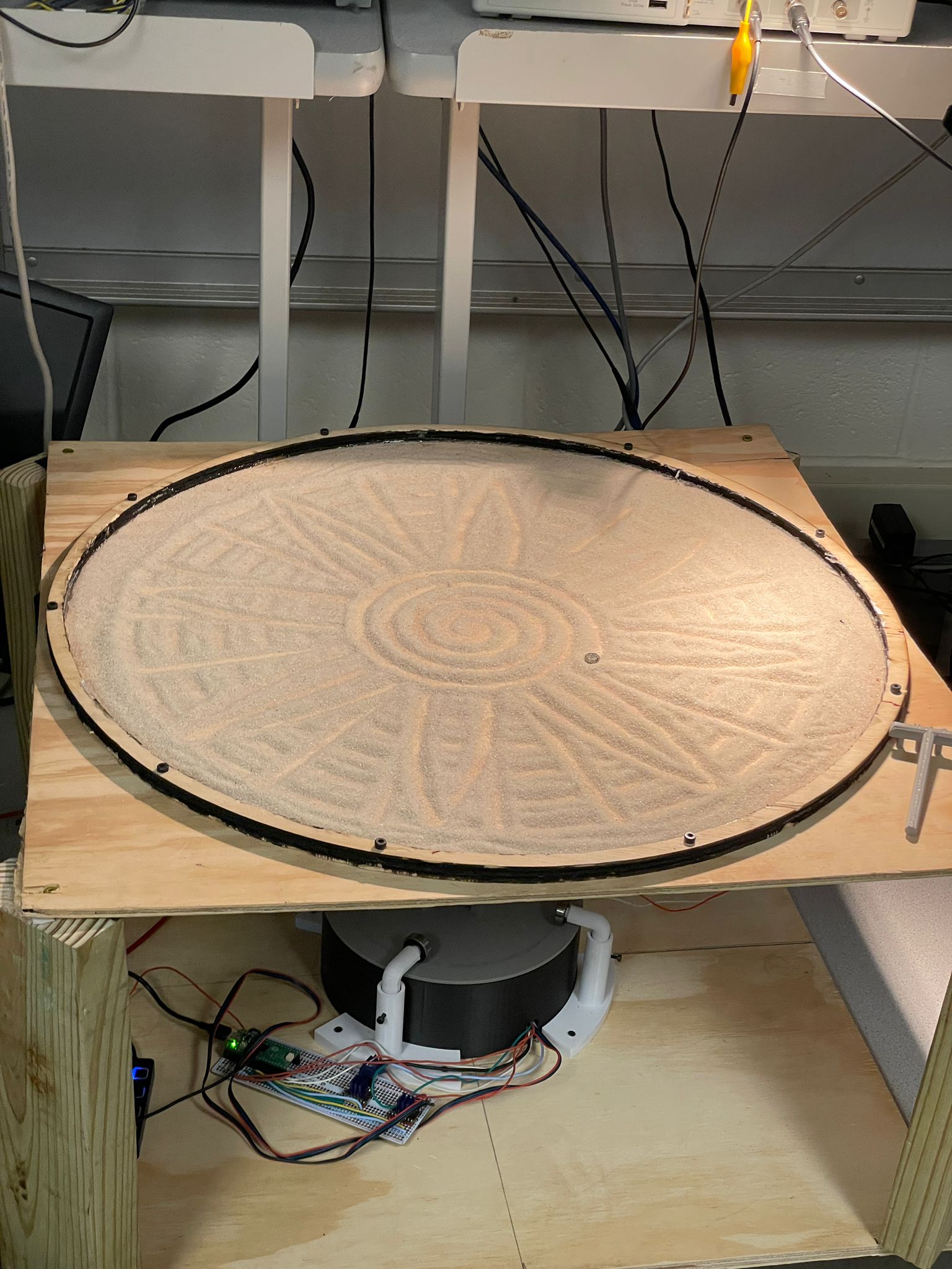
This project explores the design and fabrication of a Sisyphus-inspired sand drawing table, a kinetic sculpture that creates intricate patterns by dragging a steel ball through sand using a magnetic system beneath the surface. The table operates on a polar coordinate gantry system, a rototating arm beneath the table with a motorized gantry that slides along its length. This system is powered by two stepper motors and controlled through a Raspberry Pi Pico, enabling the steel ball to draw complex geometric patterns in fine sand.
Project Objective:
- Design and build a functional Sisyphus sand drawing table using a polar coordinate gantry system
- Implement precise motor control using stepper motors and TMC2209 drivers
- Design and fabricate custom components via 3D printing and laser cutting.
- Explore pattern generation algorithms, including circular, spiral, and heart shaped patterns
Design
Hardware Design
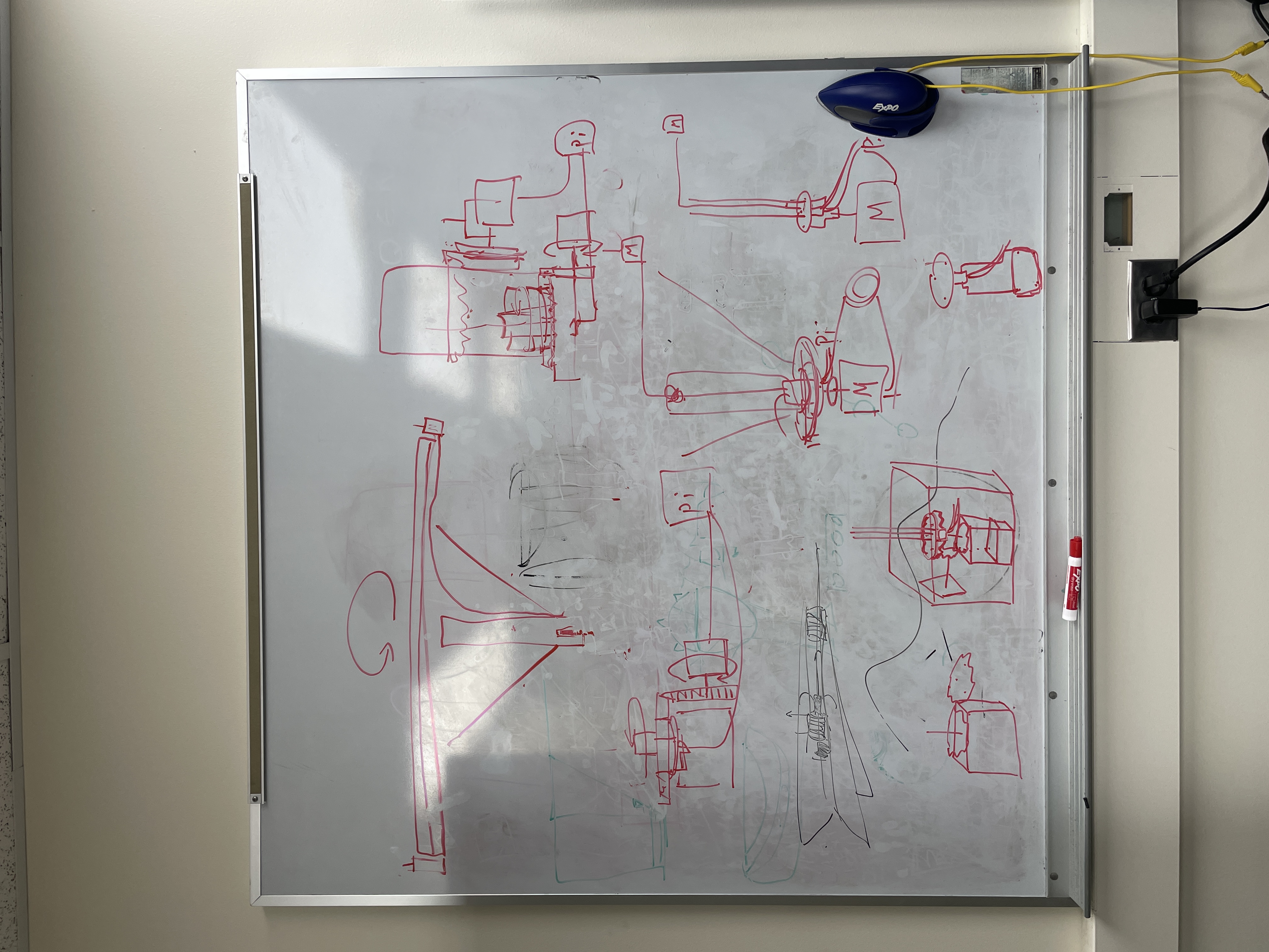
As part of the hardware design process, there were many meetings being held in front of a white board since none of the team members had any background in mechanical engineering. These sessions were essential to break down the challenges step by step and arrive at workable solutions. For the hardware design, the system was built around two motors: one responsible for rotating the beam that supports the gantry, and the other for driving the gantry itself using a belt mechanism wrapped around the second motor. The entire setup was mounted beneath a wooden table, allowing the metal ball on top to be manipulated via magnets fixed to the gantry. This concept was partially inspired by a magnetic sand table designed by Roberto Groza.
The hardware section was divided into three main components: The wooden table, the rotating base supporting the beam, and the gantry system on the beam. The table construction was left till last, as its height and dimensions were determined by the rest of the assembly. This ensured the magnet beneath the surface would be positioned just millimeters from the table to maximize its magnetic influence on the metal ball above the table.
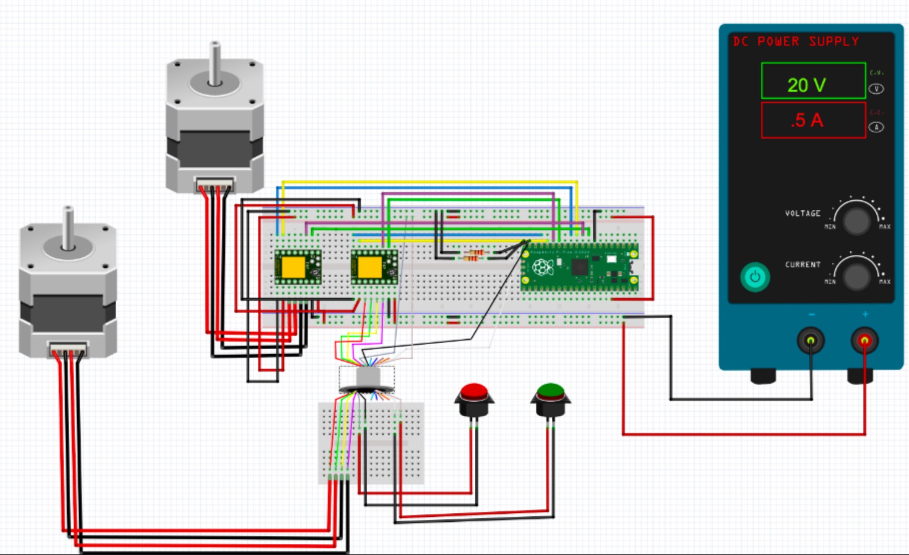
The overall circuit design ran off of two separate power sources. The RPI Pico is run off of a 5V microusb port, and powered each of the TMC2209 motor controllers off of the 3.3 volt rail. An external power supply was used in order to actually power the Nema17 motors. These motors are specified for 12 amps to 24 amps and 1.5 maximum amps. Through experimentation, we found these motors could actually be underamped to 6 volts, but would end up drawing significantly more current. For our final demonstration, we ended up running off of 20 volts as this would only draw 0.8 amps consistently. The three components that would end up spinning, being one motor and two buttons, ended running up through the slip ring such that the wires would not tangle while the table is spinning. Each button had a pull down resistor and were active high. Each motor driver has 4 GPIO pins connecting to them. These connect to a microstep 1 and 2 port, which is used to select how many microsteps the driver would take per full step. Each motor driver also had a step pin, which when it recieved a pulse, would make the motor turn one step. Finally, the motors had a direction pin, which would drive clockwise when pulled low and counterclockwise when pulled high. Each of these boards took both the 3.3V power and 20V power as inputs, and had 4 outputs total motor drive outputs.
The gantry system consisted of several custom 3D-printed parts, including a motor mount that secures to the beam, a moving gantry cart driven by the belt, and a return mount at the opposite end to loop the belt back. Multiple iterations of each component were required to fine-tune their dimensions, particularly the height and spacing, so the belt could run smoothly with minimal friction during motion. After the design was settled, buttons were added onto each side of the mount at the end of the beam so the motor could calibrate the steps required to move the gantry from one end to the other. This was implemented to ensure the gantry cart would not slide off the end of the beam and collide with the mounts.
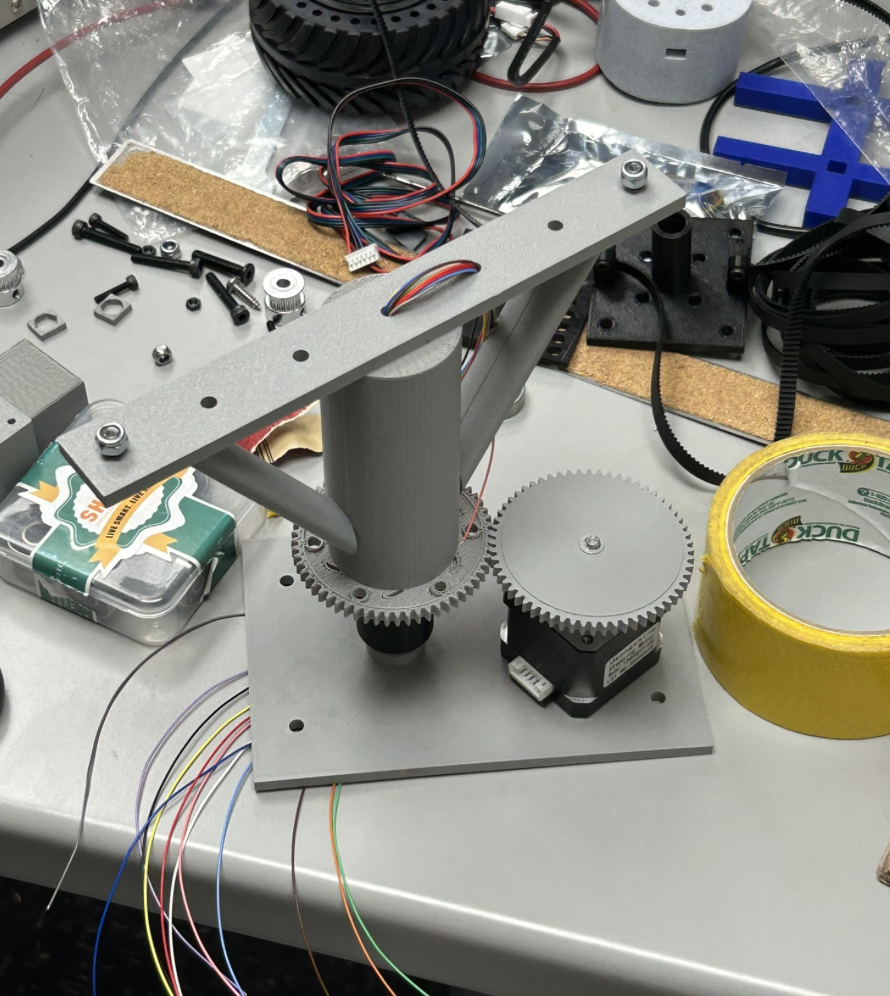
One of the biggest challenges in this project was creating the system to spin the metal bar. This was one of the most critical systems as it needed to hold the full weight of the aluminum bar and the attached motor while wobbling as little as possible while spinning. Additionally, since wires needed to be ran to the motor driving the gantry and each of the end switch buttons, the wires needed to not tangle while the base spun. The initial idea for accomplishing this was to create a way to directly affix the motor to the bar. However, this was scrapped quite quickly as it provided no way for the wires to not tangle. The next idea was to instead use a spur gear to spin a vertical rod that had the bar attached on top. Then, a slip ring could be used to run the wires down the center of the spinning mechanism, ideally preventing them from getting tangled. This was implemented by 3D printing a piece that could attach to the T-slot bar via M5 screws, screwing in tight to it. The slip ring then slotted in to the bottom of this piece, and another 3d printed part would clamp it in place. This second part could then be fit on top of a rod with bearings on it to spin freely. This can be seen below:
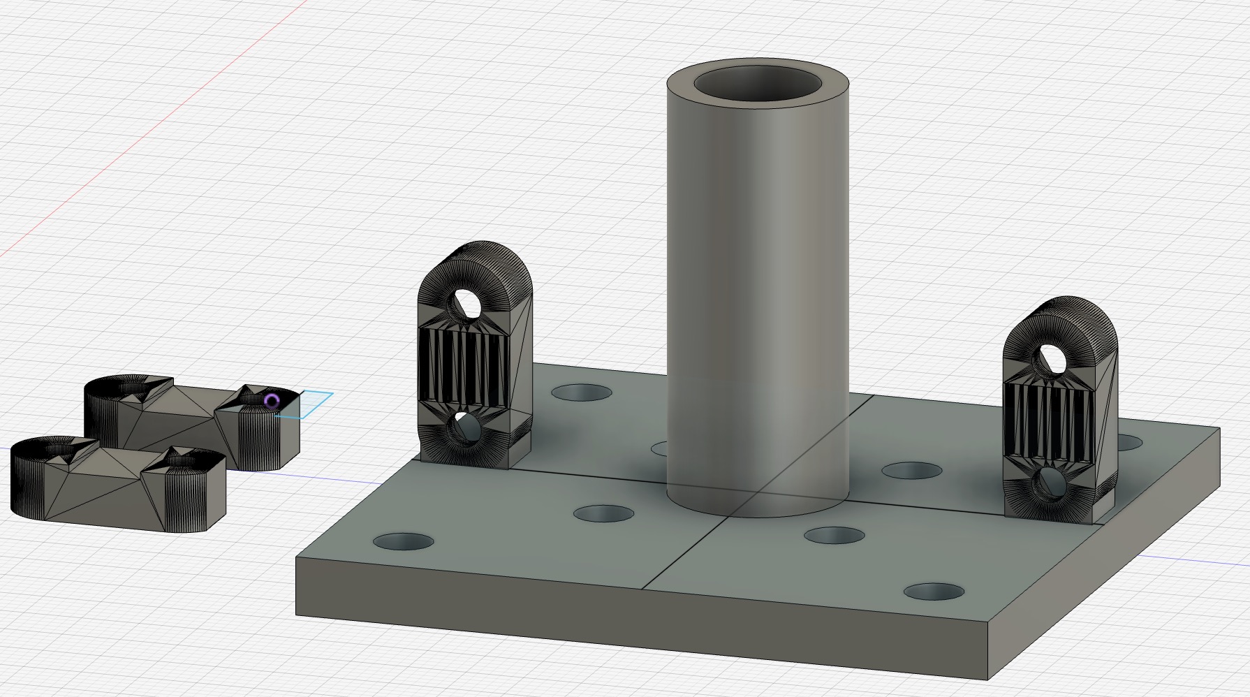
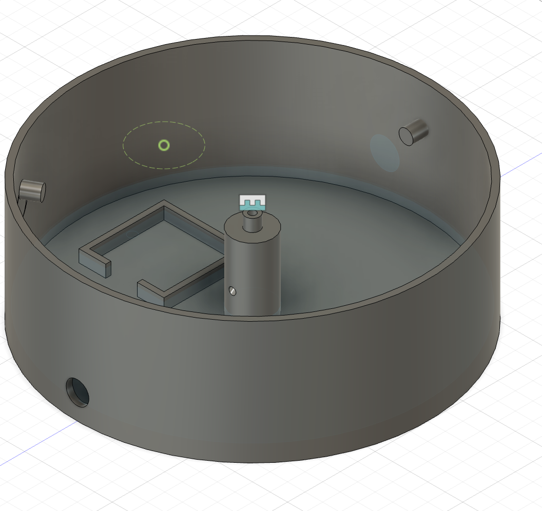
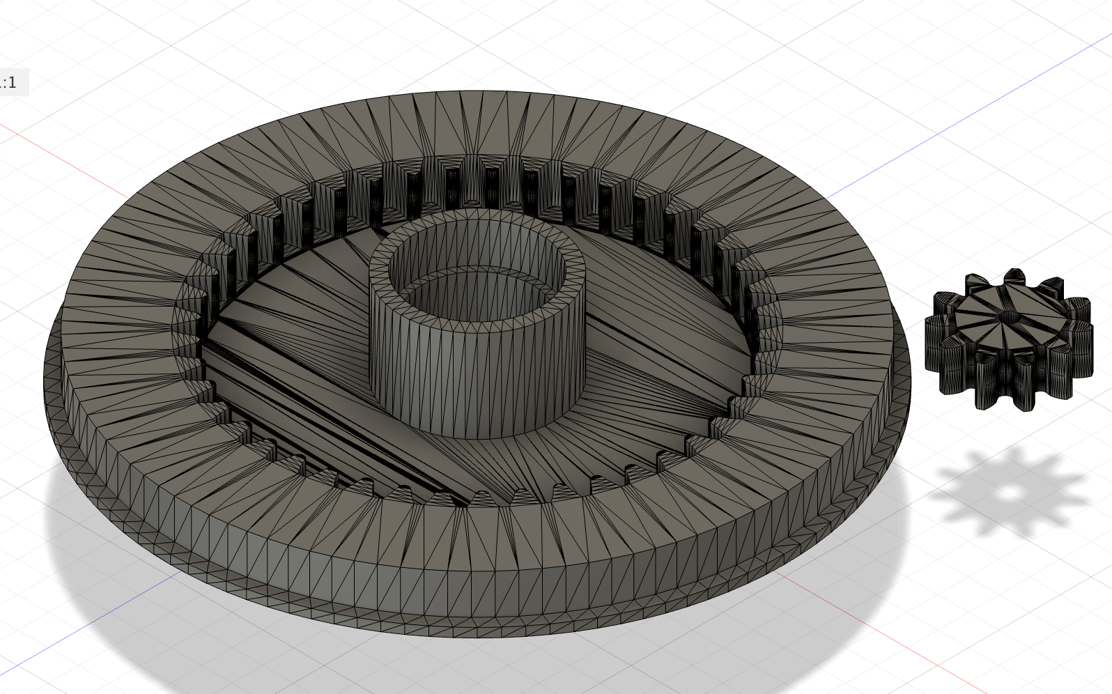
While this design did spin and attach to the bar firmly, due to being attached to the base only via one rod, it wobbled quite a lot, meaning that it would make for shaky patterns. Thus, we decided to redesign this base mechanism to be more stable. This was done by making the base far larger by making it function as a rotary table. Instead of the earlier spur gear design, a plate that was sitting on top of bearings was spun using a planetary gear. By having a much larger base and more points of contact, this design was much more stable. The cad for this redesign is shown below, as well as the assembly:
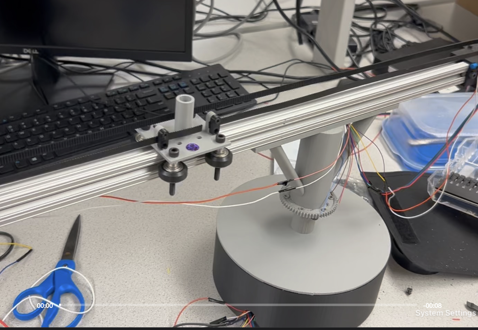
However, this redesign still had a flaw, as nothing was holding the top of the container down. This meant that depending on the gantry position, it would lift off the top of the container. To solve this, additional mounts were added to use bearings to clamp the top down. These would mount into the base board and screw in to hold the top down. This resulted in a stable base that was able to spin consistently smooth.
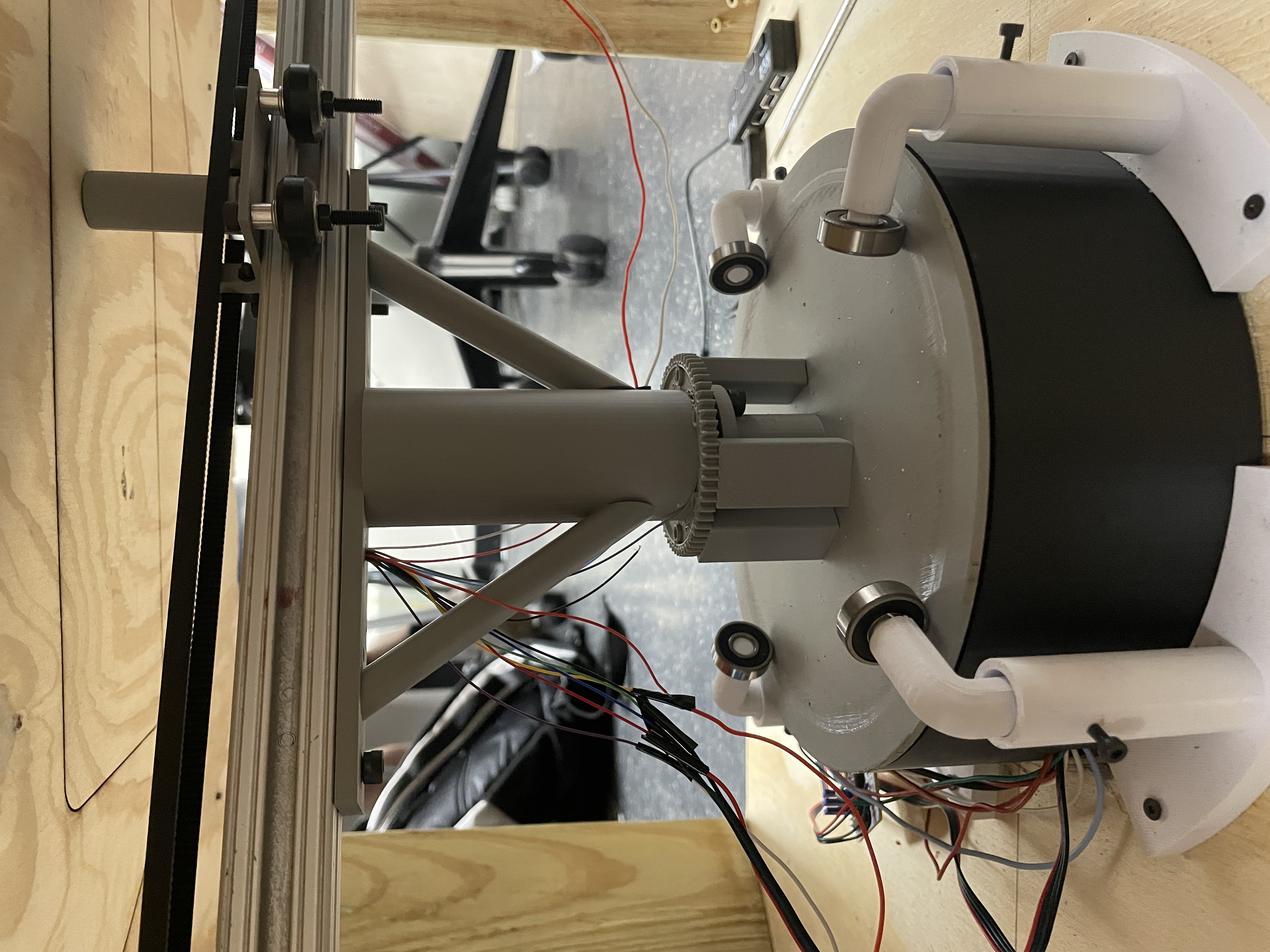
After testing the system a few times, it was clear that the beam was still unstable. The problem stems from the 3D printed material between the shaft and the rotary table whad too little infill to support the spinning beam. The proper way to solve the issue would have been to reprint the shaft to have stronger support as it did to hold the beam up. However, that would have taken too much time so it was decided that the gear printed on the shaft could be used as the top of a support and rectangular structures could be tight fit in between. By elevating the heavier side with the motor, the magnet height would become even resulting in more consistant results.
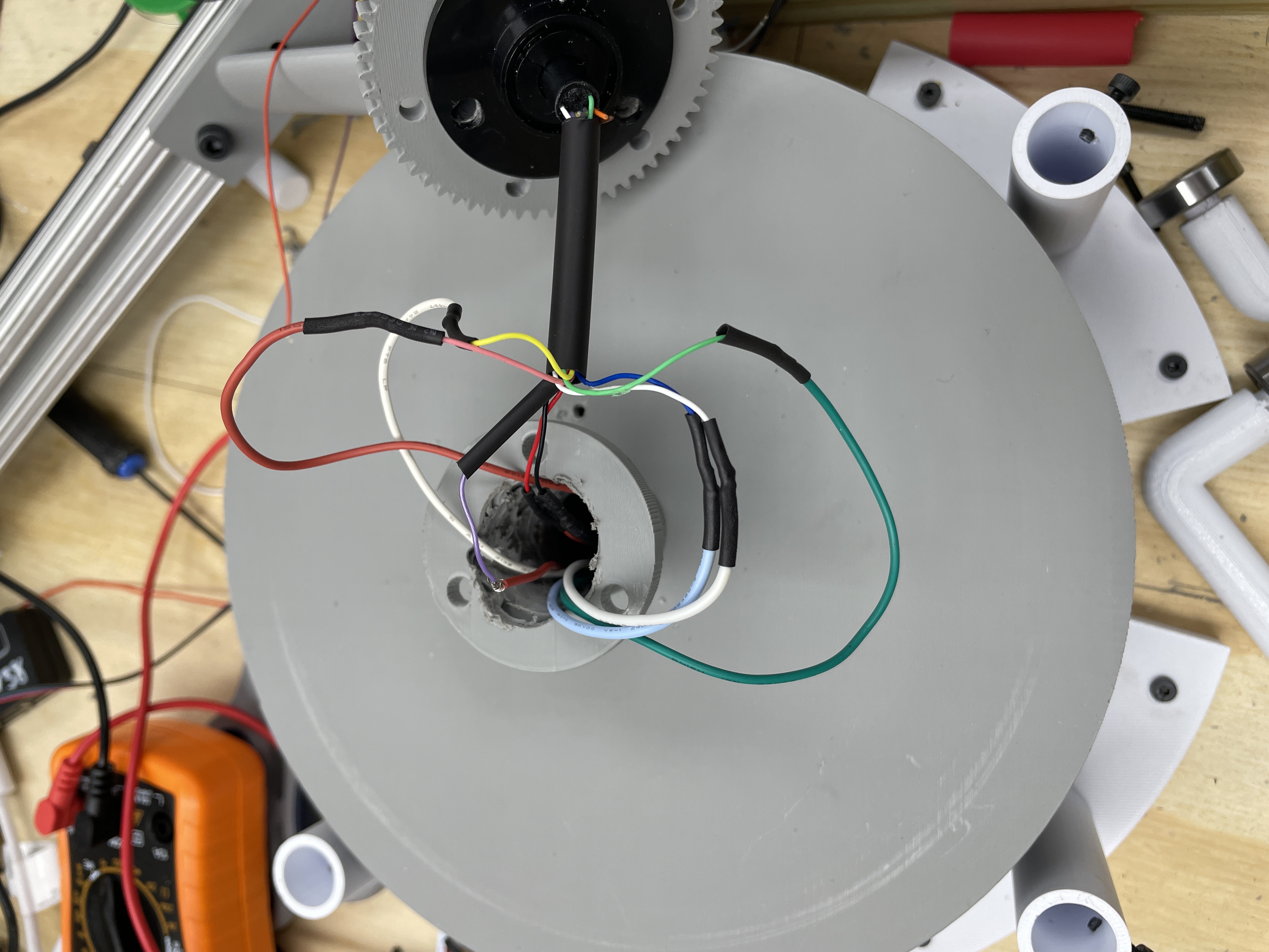
Another problem that came up was that the space for the slip ring was too tight, causing the wires to get caught on the side wall and get twisted as the beam spins. Additionally, some of the wires started behaving faulty, specifically for the buttons. This meant that the whole setup needed to be removed and wires were resoldered as some got snapped. To solve this issue, the first thing that was done was to apply heatshrink on top of all the wires together to ensure it could not get twisted. The second step taken to ensure that the wires had more space so they could spin freely, which was accomplished by widening the channel they were run through. When the connections were resoldered, each of the connections were tested with a multimeter to ensure consistent connectivity and no shorts. With all of this troubleshooting completed, we ran some more comprehensive system tests such as running the base contiguously for an extended period of time to ensure that the wires were not getting twisted. Additionally, the behavior of the gantry and buttons was verified, and it was all tested together, validating each component.
The actual table itself is constructed of 1/4 inch wood as the surface for the sand to be on, using 2 by 4s as legs for the table. The total dimensions came out to be 605mm by 605mm by 330mm. By building the table as a square, it gave just enough clearance for the 640mm bar to spin underneath without collision. The base board for the table was made of 1/2 inch wood to screw mount everything on. A ring of diameter 595mm was laser cut out of 1/2 inch wood in order to keep the sand within the table throughout the trials. In order to ensure that the gantry wouldn't drag on the bottom of the table, we additionally printed out spacers to allow us to adjust the height of the table by a few millimeters at a time.
Software Design
The software for this project consisted of one main thread that controlled
both the base and gantry motor drivers, and could drive them through a variety of predefined patterns.
The first step for this code was to set up a simple interface to abstract the driving of each motor.
This was accomplished by creating two functions, named movegantry and movebase. Each
of these take a desired position for the motor as an input and would move the motors to that position. The TMC2209 motor
drivers used functioned by stepping the motor each time a pulse was recieved on the step pin. Thus, we could track the position
of each motor in terms of the steps that they had taken, and set a desired position also in terms of steps. These functions would
then calculate how many steps forwards or backwards were needed to acheive the position, and then oscillate the step pin for the
respective motor driver to make those steps occur. A delay was also taken as an input, which specified how long of a delay was between
each pulse. This consequently would control the speed at which the motor would reach the position. Each of these functions would also
write to the direction pin for the motors to ensure they went the correct direction.
In order to use these functions, a maximum and minimum number of steps needed to be defined for both motors. For the base, it was
simple enough to calculate, as the maximum number of steps was just how many steps were required to go in a full circle. The gear ratio
of the motor to the base was 11:45, and each step was 1.8 degrees, meaning that about 818 steps would make for a full circle. Notably, it was
important to code to make the base take the shortest path possible for the base, so it could go from 359 degrees to 1 degrees without doing a
full circle. The gantry motor was a bit more difficult to work with, as the location of the gantry isn't known on startup. This is also true with
the base, but the base's starting location doesn't impact the patterns. However, the gantry needs to be started at a known position in order to draw
patterns and ensure it doesn't drive past the safe limits of the gantry. To accomplish this, a calibrate function was made to put the
gantry at a set position. This functioned by driving the gantry until it hit one of the buttons. It would then swap the direction by writing to the
direction pin and start counting steps until the endswitch on the opposite side was hit. Once this occured, the position of the gantry was known and
how many steps it took to navigate the full bar was also known. With these two functions in place, they could be used to snend the gntry to ayne theta and
radius co-ordinate on the table.
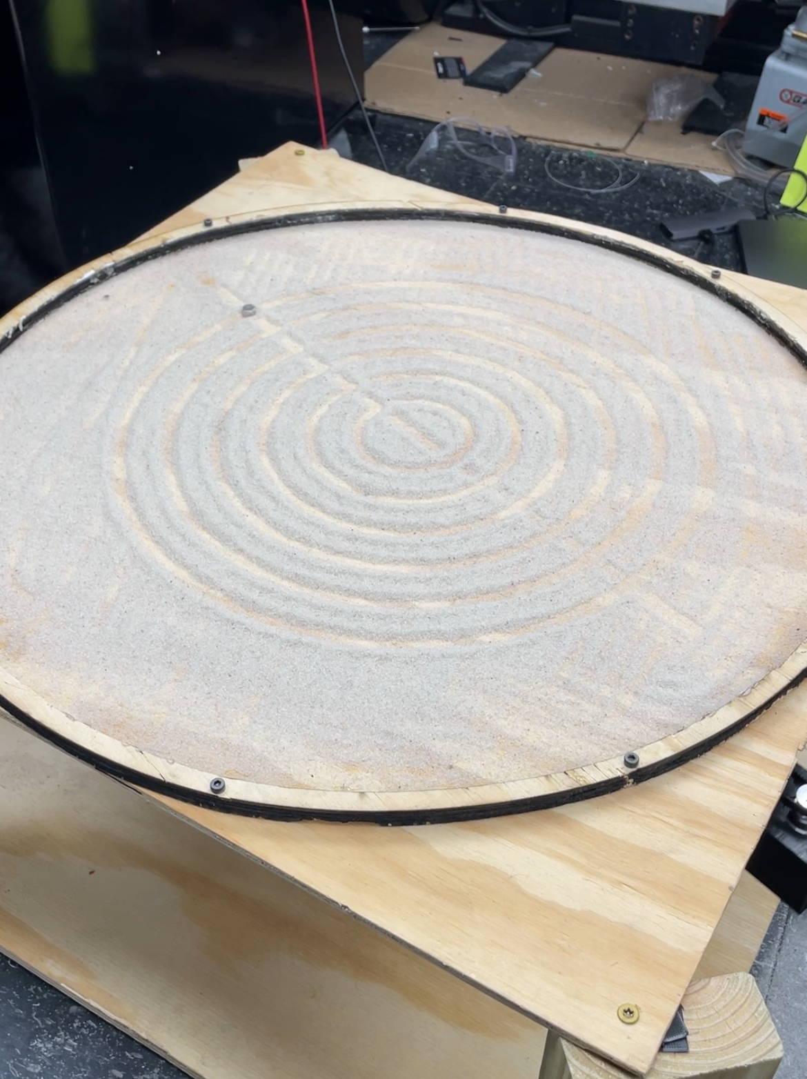
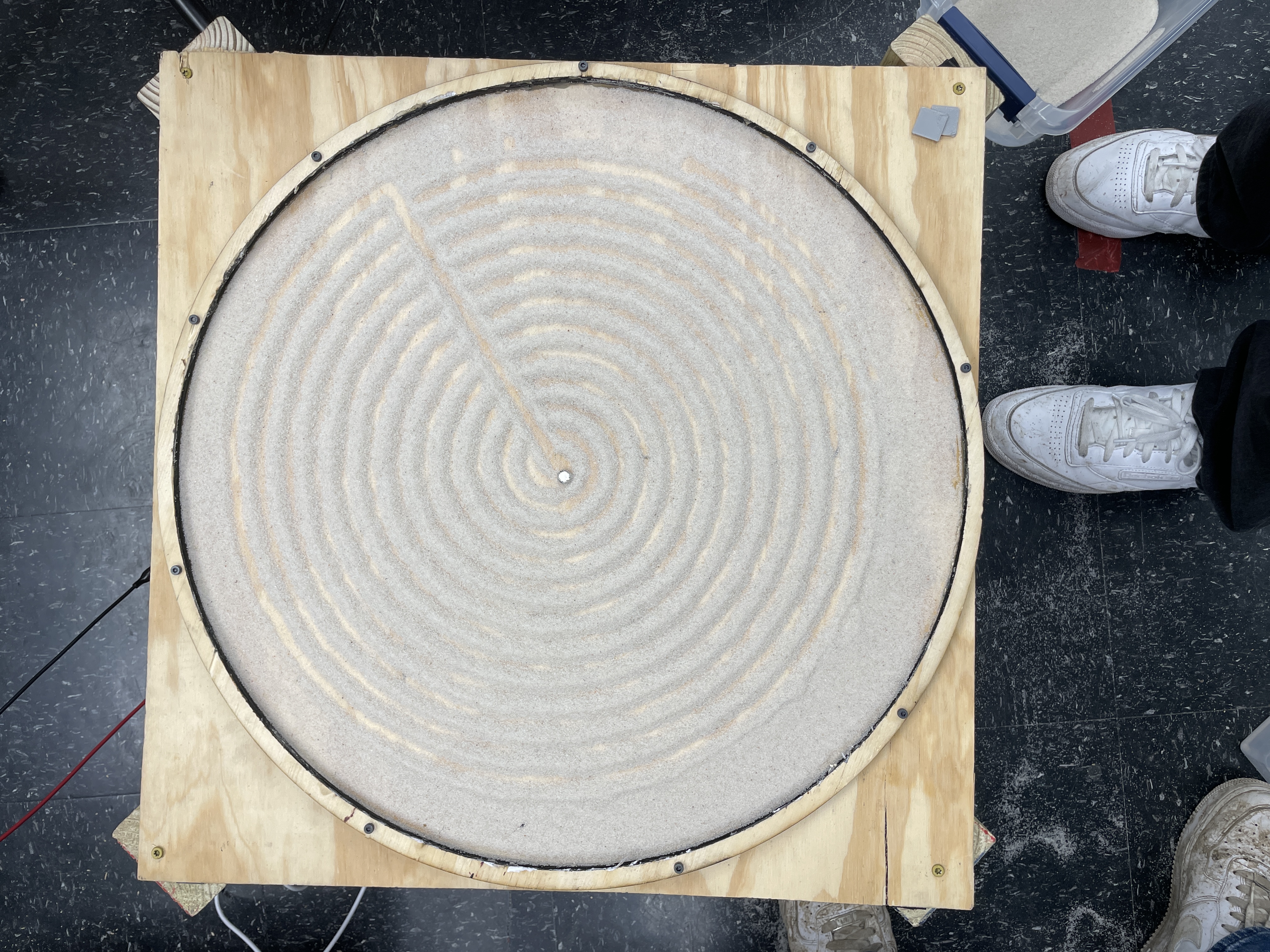
One other simple helper function that was added was called sandcircle, which simply
commanded the base to complete one circle. This was useful for the first of the patterns that was implemented, which was drawing
concentric circles in the sand. This serves to erase any existing pattern on the board, and was run right after the
calibration. This functioned by putting the gantry at the midpoint of the table, and then alternating stepping the gantry and spinning
the base for a full circle. This was implemented by scaling the increment to the gantry position off of the length of the bar in steps,
ensuring that 8 concentric circles were always drawn.
Once this function was implemented, a problem was discovered with the current configuration, where the base motor would lurch and move choppily on start up. This was slightly perplexing as this behavior was not observed earlier when running tests on the motor without load. After some experimenting, it was discovered this only occured when the motor suddenly started taking a lot of concurrent steps; at lower speeds, the motor would move smoothly. Our initial approach to fix this was to implement a windup timer, where the delay between pulses would start larger at 300 microseconds and decay down to 150 microseconds, accelerating the motor slightly slower. This helped a bit, but some startup choppiness was still observed. The next attempt to resolve this was by utilizing the microstepping of the motor. By setting the motor to take 64 microsteps per full step, the motion was smoothed out due to the more fine grain control, resolving this issue. Notably, this raised the number of steps per revolution to 52,364.
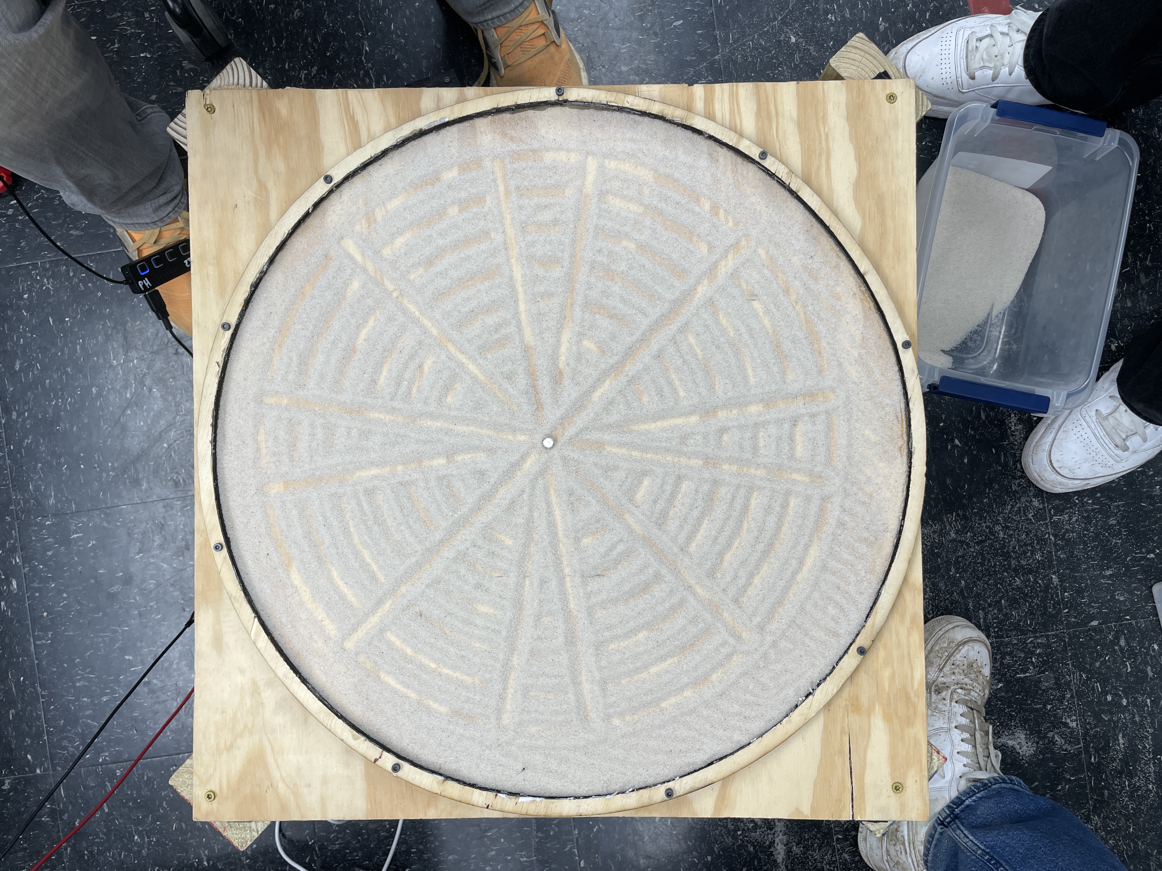
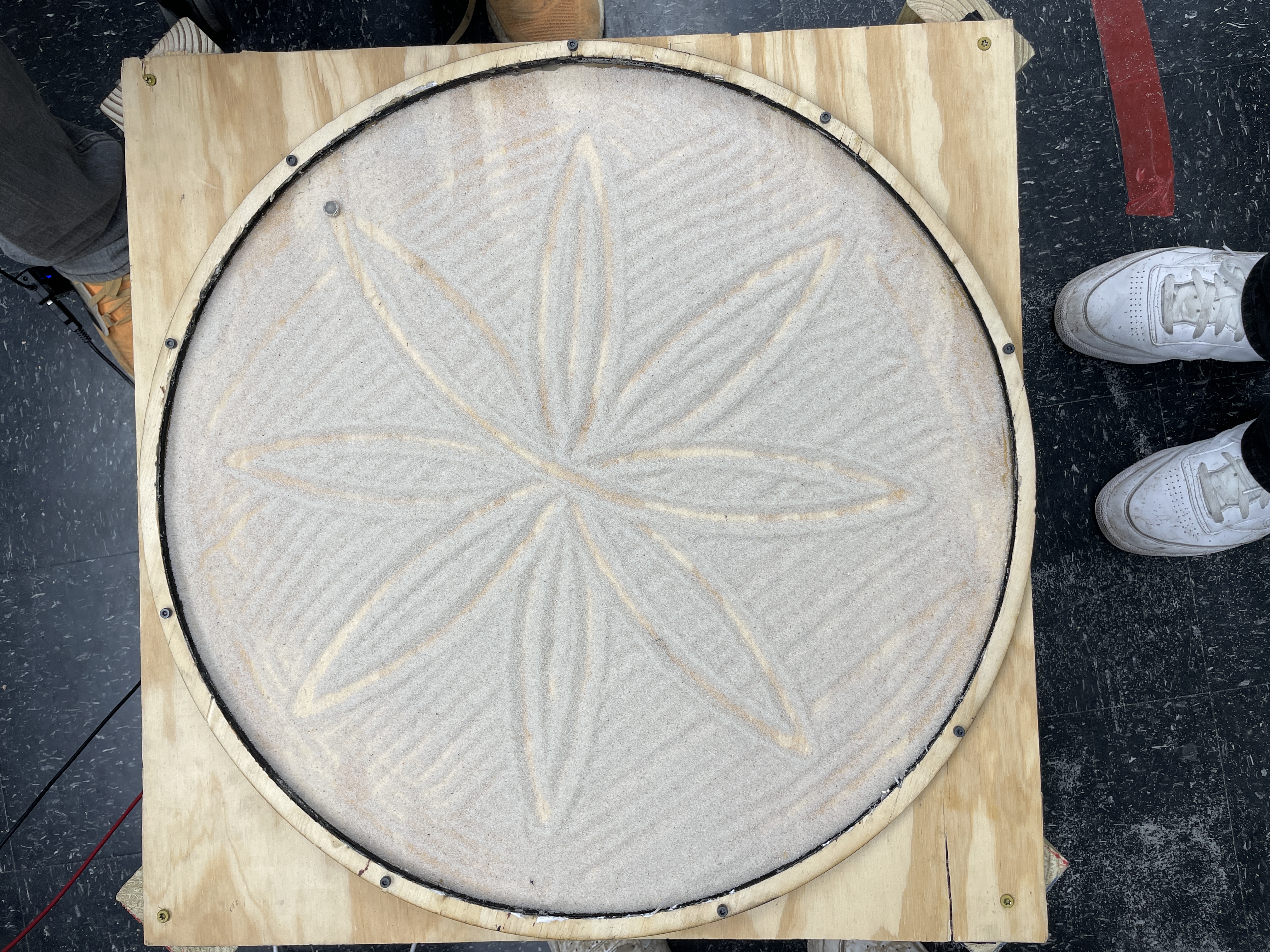
The next pattern implemented was drawing full lines through the sand at incrementing angles, which was named as a starburst pattern. This functioned very similar to the concentric circles, except the gantry was driven through its full range of motion, and then centered, and then an incremental base rotation occurred. This was able to be implemented easily with just the afforementioned functions.
While both of the previous designs were cool to get working, they would run one motor on its own, and then the other on its own.
For the next pattern, both motors were moved nearly simultaneously to create flower petals. Unlike the past patterns, the gantry and
the stepper motor were incremented by only small amounts at a time, allowing for the creation of a more complex shape. The gantry was stepped just one
step at a time until the end of its range, and then reversed and stepped in the opposite direction. In order to make a petal shape, the line
float rot_per_step = (float)STEPS_PER_REV / (petal_count * barsteps); was used to calculate how many rotational steps needed
to occur per gantry step. This functioned by taking the number of steps in one full circle and dividing by the steps in the length of the bar,
multiplied by the number of petals wanted, as this would be how many times the gantry had to move the full length of the bar.
This also allowed for easily changing the number of petals drawn by just changing the petal count. This approach only functioned because a significant
number more steps were needed to complete a full circle than going the length of the bar, due to the microstepping of the base.
The next pattern implemented was a variation on the concentric circles, drawing a spiral instead. The function drawSpiral took in
arguments for the space between each of the spirals, how many total spirals to draw, and the amount that the base would be stepped for each iteration.
The number of spirals was used to compute a maximum theta value that was iterated over, and the spacing was used to compute how much the gantry needed
to step each iteration. This required a bit of tuning to get to work nicely, as too small of a base stepping value would make the spirals take far too long
to draw, but too large of a value made the the spirals less smooth and look more like line segments.
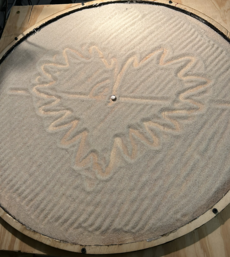
The final pattern implemented was a lace heart, which was a heart shape with some ripples added to it. This was based on the following parametric equation for a basic heart shape:
x(t) = 16·sin3(t)
y(t) = 13·cos(t) − 5·cos(2t) − 2·cos(3t) − cos(4t)
for t ∈ [0, 2π]
This parametric equation allowed to step through the heart pattern, with t just being an iteration in a for loop.
The polar coordinates could then be calculated from the x(t) and y(t) values and used to send commands to
the gantry and base. Additionally, the pattern had to be scaled down in order to properly fit on the table. Through experimentation,
it was found that a scaling of 0.7 was good. Finally, in order to make the pattern a bit more intricate, ripples were added.
This was done by adding an additional sine wave to the x and y values. This sine wave was computed with the line
float ripple = ripple_amp * sinf(ripple_freq * (angle + layer * 0.1f));. A layer variable was added to
make the sine wave slightly offset each time the that the heart was drawn over, making for a more intricate design.
This heart was drawn 5 times like this.
Each of the afformentioned patterns were ran in a predetermined order in an infinite while loop. This allows for the table to infinitely run, even if there is no user input. Conversly, the current implementation does not support the user selecting a pattern without changing the code. In the future, it would be good to add a keypad or some other sort of user interface to allow them to select different modes.
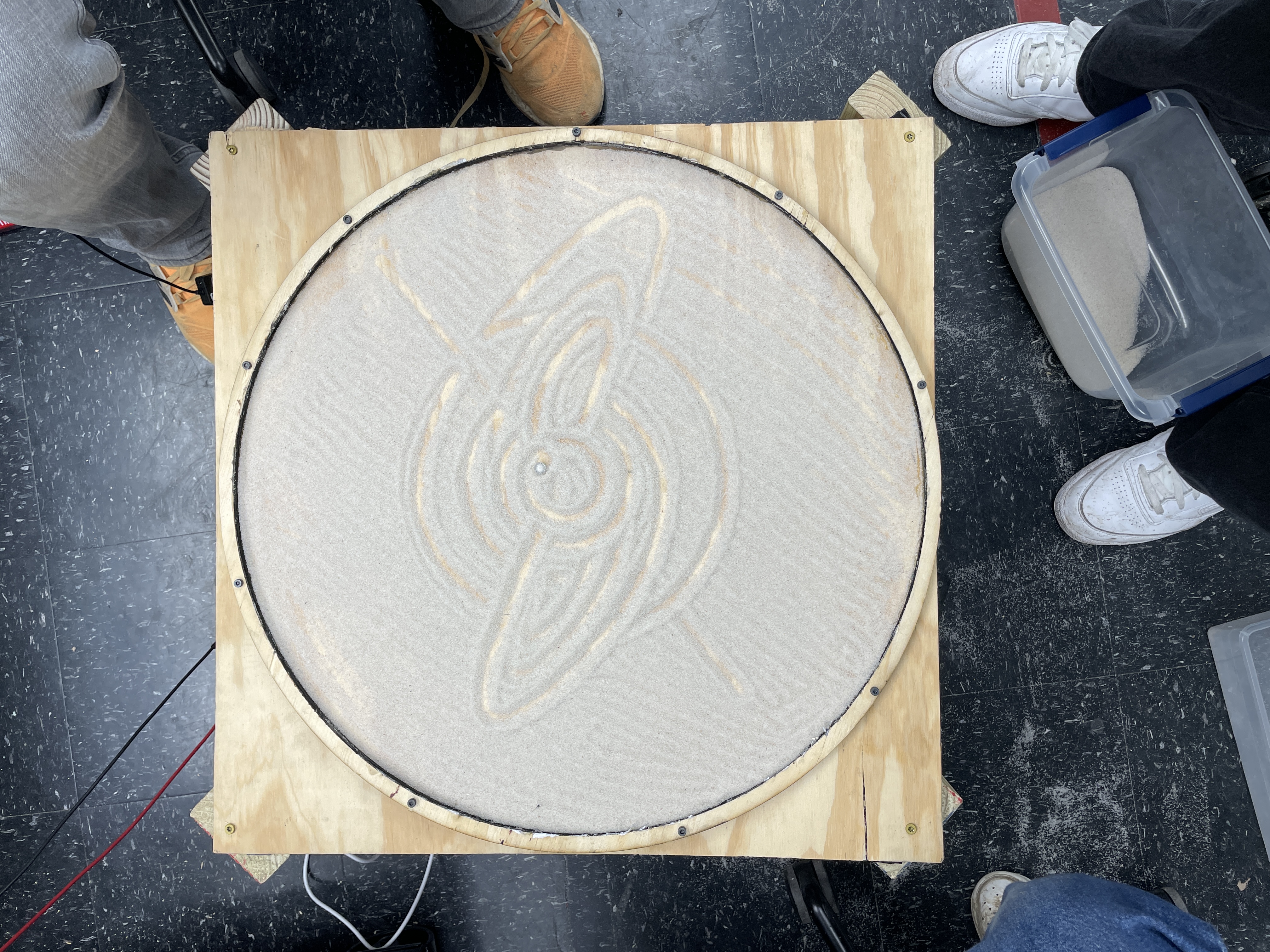
Two additional functions were attempted to be implemented. One of these was to draw the Lorentz Attractor function, which is a system of 3 differential equations that is meant to appear chaotic. However, the implementation would draw the first loop of the pattern, and then end up getting stuck at the origin. This is likely either a bug with the implementation of the function or with the parameters used for the equations, but ultimately it was not possible to debug this in time. One other attempted pattern was a simplistic bird, composed of ovals, circles, and line segments. However, this once again was unable to be completed within time. These functions would be an area to expore in the future. Below is an image of the faulty Lorenz system:
One other potential change to the software that could have been implemented was running it as a multicore program. In the current implementation, the gantry and base can never truly move simultaneously, with one moving and then the other. A multicore implementation could circumvent this by having one core control the gantry and one control the base. However, this was decided against as it could lead to synchronization issues and the single core approach functioned well enough.
Results
With both the hardware and software complete, we were able to finally integrate everything together to complete the full table. However, there was an immediate problem. Our original plan was to use a magnet on the gantry to drag a 3/8 inch chrome ball bearing through the sand to create our designs. The initial testing we did made it seem like the magnet was sufficiently strong to drag the ball while on the other side of the wood. Once the sand was in place though, the magnets simply were not strong enough to drag this large of a ball bearing, with any quick motion causing the ball bearing to decouple from the magnet. We also tried smaller ball bearings, which worked somewhat better, but unless the sand was perfectly level, the ball could get stuck on any ridges made on the sand. Without much time to get stronger magnets, we instead pivoted to using a magnet on top as the drawing implement. This worked better, although it caused jerkier movement and more noise than desirable due to the added friction of the magnet on the table top. With this however, the sand table was able to function, being able to draw each of the patterns in the sand.
In regards to the precision of the magnetic cart, the results were actually pretty impressive. The movement of the gantry and the base were incredibly quiet and were very consistent in reaching end poses. One concern was that over time the stepper motors may slowly drift, either by failing to take a step or taking an extra step. However, this ended up not being the case, as the gantry motor never ended up going beyond the bounds and in the concentric circle pattern, it is seen that each circle is ending at the same point, and full circles are being drawn every time. This consistency made it so the table could repeatedly draw patterns over an extended period of time, with the patterns always coming out roughly the same quality.
One limit of the table was within the speed of drawing. The drawings couldn't be completed too fast as it would cause the magnets to decouple. Additionally, the way that the code was implemented, the spinning of the base was almost always at a constant speed. This meant that the magnet would move very slow while in the center of the table and much faster at the edges. While this isn't inherently a problem, it does make certain patterns seem peculiar, being particularly notable in the spiral. With a stronger magnet and using a chrome ball, ideally the table would be able to draw patterns faster without risking losing the ball.
The design ended up being decently user friendly, as just the Raspberry Pi pico and external power needed to be turned on to run it. Afterwards, the table would automatically cycle through patterns. One restriction of this is that the table is currently powered by a power supply that uses alligator clips to connect the power. A cleaner approach would be to have a power block that could directly connect to an outlet and plug in, making the design cleaner. Additionally, the power from this supply could then be stepped down to also power the Raspberry Pi, making everything able to run off of just one plug. As earlier noted, it would also be beneficial to add some way for a user to see what pattern was currently being drawn and select which patterns to display without needing to recompile the code. This could be accomplished either with a keypad or a touch screen of some sort.
Conclusion
The Sisyphus-inspired sand drawing table successfully brought together mechanical design, embedded systems, and artistic expression to create a functional kinetic sculpture. By utilizing a polar coordinate gantry system driven by two stepper motors and controlled via a Raspberry Pi Pico, the table was able to draw intricate patterns such as spirals, concentric circles, starbursts, and heart shapes in fine sand. Throughout the project, the team overcame significant challenges in mechanical stability, motor synchronization, and magnetic control, refining both the hardware and software through multiple iterations. While the final system performed reliably, certain limitations such as the drawing speed being constrained by magnet strength and the sensitivity of the sand surface were faced, highlighting opportunities for future improvements. Enhancing the design with stronger magnets, a more rigid frame, and user-interactive features would further elevate its performance. Overall, the project served as a valuable exploration of robotics, motion control, and creative design, offering a strong foundation for future work in kinetic art and automated pattern generation.
All in all, our table was able to do what it was originally designed to do: create an image out of sand. However, the way we ended up doing so was not the means we intended to. We would much preferred to use a ball instead of a magnet in a future iteration which is a simple fix by buying stronger magnets. Even though we did purchase new magnets, the new magnets weren't as powerful as we expected with its rating of 18lbs of magnetic force. Whilst this is a lot, it wasn't enough to drag the ball through the sand. Furthermore, we can clean up the table so that it doesn't look like it was made with random scrap pieces of wood that were hacked together. The wood table top itself, had a few holes that we repaired by putting glue, however, instead we should've properly used wood epoxy to cover any holes and scratches created. Furthermore, we could've also painted/coated our wood to make it more aesthetically pleasing to have around. Specifically painting the table black, would allow for the drawing created by the contrasting sand color to pop out more. Another aesthetic is a LED band that can be wrapped around the circumference of the table to make it more visually appealing. Additionally, an acrylic or clear glass top can make the table into a more functional tabletop rather than just a novelty.
One other interesting option for expanding on this project would be to implement a way to import images and convert that into a path plan for the gantry to follow. This would be quite nice since it is quite time consuming to manually implement new patterns. A cohesive approach could take a vector image and convert it into lines to be followed by the gantry.
Regardless, this sand table proved to be a very fun and educational project, giving us experience with implementing a mechanical system from the ground up and creating a control system for it. Getting to see the project come to fruition was very gratifying, and it would be fun to expand on in the future.
Work Distribution
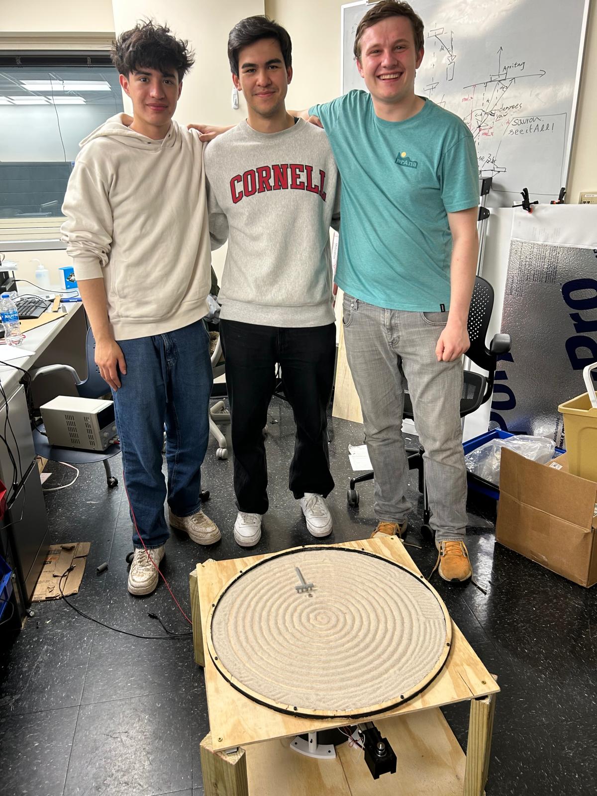
Project group picture

Aidan Derocher
ajd332@cornell.edu
Software Implementation & CAD.

Jorge Corpa Chung
jc3656@cornell.edu
CAD & Soldering

Henry Calderon
hcc54@cornell.edu
Helped with software implementation, assembly, and soldering
Parts List
- Raspberry Pi pico - Sourced from lab
- Motors: 2 x Nema 17 - $15.98
- Wiring: Slip ring - $17.68
- Gantry magnet: Magnet - $7.60
- Surface Ball: Ball - $5.75
- Gantry Belt: Belt and pulleys - $14.99
- Motor drivers: 2 x TMC2209- $13.99
- White sand: sand - $14.39
- 0.5 Inch Wood for Table - $15.00
- 2x4 Wood for Table Legs - $5.00
- 0.25 inch wood for table - Sourced from lab
- 3d printed components - Sourced from lab
Total: $110.38
Appendix A
- The group approves this report for inclusion on the course website.
- The group approves the video for inclusion on the course youtube channel.
Code Appendix
/**
* Aidan Derocher (ajd332), Henry Calderon, Jorge Corpa Chung
*
* Code to drive sand drawing table
* SAND
*
* HARDWARE CONNECTIONS - VGA
* - GPIO 16 ---> VGA Hsync
* - GPIO 17 ---> VGA Vsync
* - GPIO 18 ---> 470 ohm resistor ---> VGA Green
* - GPIO 19 ---> 330 ohm resistor ---> VGA Green
* - GPIO 20 ---> 330 ohm resistor ---> VGA Blue
* - GPIO 21 ---> 330 ohm resistor ---> VGA Red
* - RP2040 GND ---> VGA GND
*
* RESOURCES USED
* - PIO state machines 0, 1, and 2 on PIO instance 0
* - DMA channels (2, by claim mechanism)
* - 153.6 kBytes of RAM (for pixel color data)
*
*/
// Include the VGA grahics library
#include "vga16_graphics.h"
// Include standard libraries
#include
#include
#include
#include
// Include Pico libraries
#include "pico/stdlib.h"
#include "pico/divider.h"
#include "pico/multicore.h"
// Include hardware libraries
#include "hardware/pio.h"
#include "hardware/dma.h"
#include "hardware/clocks.h"
#include "hardware/pll.h"
//#include "hardware/i2c.h"
// Include protothreads
#include "pt_cornell_rp2040_v1_3.h"
// === the fixed point macros ========================================
typedef signed int fix15 ;
#define multfix15(a,b) ((fix15)((((signed long long)(a))*((signed long long)(b)))>>15))
#define float2fix15(a) ((fix15)((a)*32768.0)) // 2^15
#define fix2float15(a) ((float)(a)/32768.0)
#define absfix15(a) abs(a)
#define int2fix15(a) ((fix15)(a << 15))
#define fix2int15(a) ((int)(a >> 15))
#define char2fix15(a) (fix15)(((fix15)(a)) << 15)
#define divfix(a,b) (fix15)(div_s64s64( (((signed long long)(a)) << 15), ((signed long long)(b))))
// uS per frame
#define FRAME_RATE 33000
#define LED_PIN 25
//Stepper motor pins
#define BASESTEPPIN 8
#define GANTRYSTEPPIN 12
#define BASEMICROPIN1 6
#define BASEMICROPIN2 7
#define GANTRYMICROPIN1 10
#define GANTRYMICROPIN2 11
#define BASEDIRPIN 9
#define GANTRYDIRPIN 13
//calibration buttons
#define ENDBUTTON1 14
#define ENDBUTTON2 15
//Steps per revolution
#define STEPS_PER_REV 52364
#define LORENZ_STEPS 100000
//Bar calibration
volatile int barsteps = 0;
//Lorenz storage
int r_steps[LORENZ_STEPS];
int theta_steps[LORENZ_STEPS];
// Positions in steps
volatile int gantry_pos = 0;
volatile int base_pos = 0;
// the color of the boid
char color = WHITE ;
// Magnetic ball Postion
volatile float radius = 1;
volatile float theta = 0.78;
volatile float dr = 0;
volatile float dthet = 0;
volatile float x = 0;
volatile float y = 0;
volatile float centerx = 320;
volatile float centery = 240;
char screentext[40];
bool calibrate(int firstdir) {
gpio_put(GANTRYDIRPIN, firstdir);
int start_calib = time_us_32();
int gantrystep = 0;
//Step until hit button at one end
while(time_us_32() - start_calib < 30000000) {
gantrystep = !gantrystep;
gpio_put(GANTRYSTEPPIN, gantrystep);
int button_count = 0;
if(gpio_get(ENDBUTTON1)!=0) {
for (int i = 0; i < 10; i++) {
if(gpio_get(ENDBUTTON1)!=0) {
button_count ++;
}
}
if(button_count == 10) {
gantrystep = 0;
break;
}
}
sleep_us(100);
}
int count = 0;
gpio_put(GANTRYDIRPIN, !firstdir);
//Measure full length of bar in terms of steps
while(time_us_32() - start_calib < 30000000) {
gantrystep = !gantrystep;
gpio_put(GANTRYSTEPPIN, gantrystep);
if(gantrystep == 1) { //Only increment on the positive step pulse
count ++;
}
int button_count = 0;
if(gpio_get(ENDBUTTON2)!=0) {
for (int i = 0; i < 10; i++) {
if(gpio_get(ENDBUTTON2)!=0) {
button_count ++;
}
}
if(button_count == 10) {
gantry_pos = 0;
barsteps = count;
gpio_put(LED_PIN, 1);
gpio_put(GANTRYSTEPPIN, 0);
return true;
}
}
sleep_us(100);
}
return false;
}
void sandcircle(int time) {
for (int i = 0; i < STEPS_PER_REV; i++) {
if (time > 150 && (i % 6 == 0)) {
time -= 1;
}
gpio_put(BASESTEPPIN, 1);
sleep_us(100); //not sure if the pulse width needs to be this long tbh but cest la vie
gpio_put(BASESTEPPIN, 0);
sleep_us(time);
}
}
void movegantry(int position, int delay) {
if(position > gantry_pos) {
gpio_put(GANTRYDIRPIN, 0);
while(gantry_pos != position) {
gpio_put(GANTRYSTEPPIN, 1);
sleep_us(delay);
gpio_put(GANTRYSTEPPIN, 0);
gantry_pos ++;
sleep_us(delay);
}
}
else {
gpio_put(GANTRYDIRPIN, 1);
while(gantry_pos != position) {
gpio_put(GANTRYSTEPPIN, 1);
sleep_us(delay);
gpio_put(GANTRYSTEPPIN, 0);
gantry_pos --;
sleep_us(delay);
}
}
}
void movebase(int position, int delay) {
// Normalize positions to within one revolution
int target = position % STEPS_PER_REV;
int current = base_pos % STEPS_PER_REV;
int forward_steps = (target - current + STEPS_PER_REV) % STEPS_PER_REV;
int backward_steps = (current - target + STEPS_PER_REV) % STEPS_PER_REV;
int time = 300;
if (forward_steps <= backward_steps) {
gpio_put(BASEDIRPIN, 0); // Clockwise
for (int i = 0; i < forward_steps; i++) {
if (time > delay && (i % 6 == 0)) {
time -= 1;
}
gpio_put(BASESTEPPIN, 1);
sleep_us(100);
gpio_put(BASESTEPPIN, 0);
base_pos = (base_pos + 1) % STEPS_PER_REV;
sleep_us(time);
}
} else {
gpio_put(BASEDIRPIN, 1); // Counterclockwise
for (int i = 0; i < backward_steps; i++) {
if (time > delay && (i % 6 == 0)) {
time -= 1;
}
gpio_put(BASESTEPPIN, 1);
sleep_us(100);
gpio_put(BASESTEPPIN, 0);
base_pos = (base_pos - 1 + STEPS_PER_REV) % STEPS_PER_REV;
sleep_us(delay);
}
}
}
void starburst_petals() {
int petal_count = 8;
float rot = base_pos; // use float to accumulate small deltas
float rot_per_step = (float)STEPS_PER_REV / (petal_count * barsteps); // small angle per gantry step
for (int petal = 0; petal < petal_count/2; petal++) {
// Outward arc
for (int r = 0; r <= barsteps; r++) {
movegantry(r, 100);
rot += rot_per_step;
movebase((int)rot, 300);
}
// Inward arc
for (int r = barsteps; r >= 0; r--) {
movegantry(r, 100);
rot += rot_per_step;
movebase((int)rot, 300);
}
}
}
void starburst() {
int rot = 0;
while(abs(STEPS_PER_REV/2 - rot) > 10) { //should do lines for 180 of the way, > 10 to account for potential roundign weirdness
movegantry(0, 100);
movegantry(barsteps, 100);
movegantry(barsteps/2, 100);
movebase(base_pos+STEPS_PER_REV/20, 300);
rot += STEPS_PER_REV/20;
}
}
void drawSpiral(float spacing, int turns, float step) {
float theta = 0.0f;
float maxTheta = 2.0f * M_PI * turns;
while (theta < maxTheta) {
float r = spacing * theta;
// Normalize radius to [0, 1] range and scale to steps
int r_step = (int)((r / (spacing * maxTheta)) * (barsteps / 2) + (barsteps / 2));
// Normalize theta to [0, 2π] and convert to steps
float wrappedTheta = fmodf(theta, 2.0f * M_PI);
if (wrappedTheta < 0) wrappedTheta += 2.0f * M_PI;
int theta_step = (int)((wrappedTheta / (2.0f * M_PI)) * STEPS_PER_REV);
// Move to this point in spiral
movegantry(r_step, 100); // Adjust delay for smoother movement
movebase(theta_step, 300); // Slower rotation for accuracy
theta += step;
}
}
void erasesand() {
//Base gear ratio is 45/11, and with no microstepping there are 200 steps per motor rev, so 818.1818 steps for one circle
//may be times 8 since gnd/gnd is 8 microsteps. in that case 6545 steps for one circle, can sleep 460 us for circle in 3 secs
movegantry(barsteps/2, 100);
movebase(0, 150);
//move the gantry 8 times, should make 8 concentric circles
for (int j = barsteps/2+barsteps/16; j < barsteps; j+=barsteps/16)
{
movegantry(j, 200);
//one circle of base
sandcircle(600);
}
}
void eraseball()
{
fillCircle(centerx+x, centery+y, 6, BLACK);
}
//lorenz equation
/*void calc_lorenz(float rho, float sigma, float beta) {
float x = 0.1f, y = 0.0f, z = 0.0f;
float dt = 0.01f;
// Allocate memory for x_vals and y_vals
float x_vals[LORENZ_STEPS];
float y_vals[LORENZ_STEPS];
float r_vals[LORENZ_STEPS];
float theta_vals[LORENZ_STEPS];
//precompute all of the x and y locs for the system
for (int i = 0; i < LORENZ_STEPS; ++i) {
float dx = sigma * (y - x);
float dy = x * (rho - z) - y;
float dz = x * y - beta * z;
x += dx * dt;
y += dy * dt;
z += dz * dt;
x_vals[i] = x;
y_vals[i] = y;
//convert to polar
r_vals[i] = sqrtf(x * x + y * y);
theta_vals[i] = atan2f(y, x); // θ in radians
}
// Find the max radius for normalization
float max_r = 0.0f;
for (int i = 0; i < LORENZ_STEPS; ++i) {
if (r_vals[i] > max_r) max_r = r_vals[i];
if (theta_vals[i] < 0) theta_vals[i] += 2.0f * M_PI; // Wrap to [0, 2π]
}
for (int i = 0; i < LORENZ_STEPS; ++i) {
r_steps[i] = (int)((r_vals[i] / max_r) * (barsteps / 2) + (barsteps / 2));
theta_steps[i] = (int)((theta_vals[i] / (2.0f * M_PI)) * STEPS_PER_REV);
}
}
void lorenz(float rho, float sigma, float beta) {
static int initialized = 0;
//Only calc out sequence on first run
if(!initialized) {
calc_lorenz(rho, sigma, beta);
initialized = 1;
}
int interp = 10;
for (int i = 0; i < LORENZ_STEPS - 1; i++) {
int r0 = r_steps[i];
int r1 = r_steps[i + 1];
int theta0 = theta_steps[i];
int theta1 = theta_steps[i + 1];
//interpolate between steps for smoother motion
for (int j = 0; j < interp; j++) {
int r_interp = r0 + ((r1 - r0) * j) / interp;
int theta_interp = theta0 + ((theta1 - theta0) * j) / interp;
movegantry(r_interp, 100);
movebase(theta_interp, 300);
}
}
}*/
// Manual min/max functions for C
#define min(a, b) ((a) < (b) ? (a) : (b))
#define max(a, b) ((a) > (b) ? (a) : (b))
void lorenz(float rho, float sigma, float beta) {
float x = 0.1f, y = 0.0f, z = 0.0f;
float dt = 0.01f;
int interp = 10;
float max_r = 15.0f; // Estimate max_r to normalize radius, tune experimentally
float max_radius = max_r; // You can adjust max_radius to control the maximum radius of movement
for (int step = 0; step < LORENZ_STEPS; step++) {
// Save previous x, y
float x_prev = x;
float y_prev = y;
// Lorenz equations
float dx = sigma * (y - x);
float dy = x * (rho - z) - y;
float dz = x * y - beta * z;
x += dx * dt;
y += dy * dt;
z += dz * dt;
// Convert both current and previous point to polar coordinates
float r0 = sqrtf(x_prev * x_prev + y_prev * y_prev);
float theta0 = atan2f(y_prev, x_prev);
float r1 = sqrtf(x * x + y * y);
float theta1 = atan2f(y, x);
// Wrap angle to [0, 2π]
if (theta0 < 0) theta0 += 2.0f * M_PI;
if (theta1 < 0) theta1 += 2.0f * M_PI;
// Interpolate between r0/theta0 and r1/theta1
for (int j = 0; j < interp; j++) {
float t = (float)j / interp;
float r = r0 + (r1 - r0) * t;
float theta = theta0 + (theta1 - theta0) * t;
// Clamp r to the max_radius
r = min(r, max_radius);
// Normalize r to the range of barsteps
int r_step = (int)((r / max_radius) * (barsteps / 2) + (barsteps / 2));
r_step = max(0, min(r_step, barsteps)); // Clamp r_step to valid range
// Normalize theta to STEPS_PER_REV and ensure it's in range [0, STEPS_PER_REV]
int theta_step = (int)((theta / (2.0f * M_PI)) * STEPS_PER_REV);
theta_step = max(0, min(theta_step, STEPS_PER_REV)); // Clamp theta_step to valid range
// Ensure movement is happening by checking the steps
if (r_step == 0) r_step = 1;
if (theta_step == 0) theta_step = 1;
// Move gantry and base with clamped values
movegantry(r_step, 100);
movebase(theta_step, 300);
// Optional: Break early if changes in r and theta are small
float delta_r = fabs(r1 - r0);
float delta_theta = fabs(theta1 - theta0);
if (delta_r < 0.001f && delta_theta < 0.001f) {
break; // Stop if changes are too small
}
}
}
}
void drawBird() {
/*float a = barsteps / 6; // semi-major axis (radial "width")
float b = STEPS_PER_REV / 10; // semi-minor axis (angular "height")
float cx = 0.0f; // x center (angle 0)
float cy = barsteps / 2.0f; // y center (radial midpoint)
int steps = 200; // resolution of the ellipse
for (int i = 0; i <= steps; i++) {
float t = 2.0f * M_PI * i / steps;
// Parametric ellipse in Cartesian
float x = a * cosf(t);
float y = b * sinf(t);
// Convert to polar
float r = sqrtf(x * x + y * y);
float theta = atan2f(y, x); // angle in radians
// Shift center
r += cy;
if (theta < 0) theta += 2.0f * M_PI;
// Convert to steps
int r_steps = (int)r;
int theta_steps = (int)((theta / (2.0f * M_PI)) * STEPS_PER_REV);
movegantry(r_steps, 100);
movebase(theta_steps, 300);
}*/
float a = barsteps / 6; // semi-major axis (radial "width")
float b = STEPS_PER_REV / 10; // semi-minor axis (angular "height")
float cx = 0.0f; // x center (angle 0)
float cy = barsteps / 2.0f; // y center (radial midpoint)
int steps = 200; // resolution of the ellipse
// First half of the oval (up to the top of the oval)
for (int i = 0; i <= steps / 2; i++) {
float t = 2.0f * M_PI * i / steps;
// Parametric ellipse in Cartesian
float x = a * cosf(t);
float y = b * sinf(t);
// Convert to polar
float r = sqrtf(x * x + y * y);
float theta = atan2f(y, x); // angle in radians
// Shift center
r += cy;
if (theta < 0) theta += 2.0f * M_PI;
// Convert to steps
int r_steps = (int)r;
int theta_steps = (int)((theta / (2.0f * M_PI)) * STEPS_PER_REV);
movegantry(r_steps, 100);
movebase(theta_steps, 300);
}
// Draw the circle at the tip of the minor axis (top or bottom of the ellipse)
// The minor axis is along the y direction, so circle will be centered on y = ±b
float circle_radius = 15; // radius of the small circle
int circle_steps = 100; // resolution for the circle
// Loop to draw the small circle at the tip of the minor axis
for (int i = 0; i < circle_steps; i++) {
float t = 2.0f * M_PI * i / circle_steps;
// Parametric circle (radius = circle_radius)
float x = circle_radius * cosf(t); // keep x fixed to 0 for minor axis
float y = b + circle_radius * sinf(t); // move along minor axis (y direction)
// Convert to polar
float r = y; // fixed distance along minor axis
float theta = atan2f(y, x); // angle in radians
// Ensure theta is within [0, 2π]
if (theta < 0) theta += 2.0f * M_PI;
// Convert to steps
int r_steps = (int)r;
int theta_steps = (int)((theta / (2.0f * M_PI)) * STEPS_PER_REV);
movegantry(r_steps, 100);
movebase(theta_steps, 300);
}
// Second half of the oval (returning to the start)
for (int i = steps / 2; i <= steps; i++) {
float t = 2.0f * M_PI * i / steps;
// Parametric ellipse in Cartesian
float x = a * cosf(t);
float y = b * sinf(t);
// Convert to polar
float r = sqrtf(x * x + y * y);
float theta = atan2f(y, x); // angle in radians
// Shift center
r += cy;
if (theta < 0) theta += 2.0f * M_PI;
// Convert to steps
int r_steps = (int)r;
int theta_steps = (int)((theta / (2.0f * M_PI)) * STEPS_PER_REV);
movegantry(r_steps, 100);
movebase(theta_steps, 300);
}
}
void drawLaceHeart() {
movegantry(barsteps/2, 100); // Start at the center
const int points = 500; // Number of points to plot the heart shape
const int num_layers = 5; // Number of layers of lace heart
const float max_r_units = 16.0f; // Maximum heart size in units
// Draw multiple layers of the heart with different ripple effects
for (int layer = 0; layer < num_layers; ++layer) {
// Add slight variations to the ripple effect based on the layer
const float ripple_amp = 1.0f + (float)layer * 0.2f; // Tweak amplitude for each layer
const float ripple_freq = 10.0f + (float)layer * 2.0f; // Tweak frequency for each layer
for (int i = 0; i <= points; ++i) {
float t = (float)i / points * 2.0f * M_PI;
// Parametric heart curve
float x = 16 * powf(sinf(t), 3);
float y = 13 * cosf(t) - 5 * cosf(2 * t) - 2 * cosf(3 * t) - cosf(4 * t);
// Scale down to fit table radius
x *= 0.7f;
y *= 0.7f;
// Ripple on the radial component, offset each time based on layer
float angle = atan2f(y, x);
float ripple = ripple_amp * sinf(ripple_freq * (angle + layer * 0.1f)); // Apply layer-based offset to ripple
float x_mod = x + ripple * cosf(angle);
float y_mod = y + ripple * sinf(angle);
// Convert to polar coordinates
float r_units = sqrtf(x_mod * x_mod + y_mod * y_mod);
float theta = atan2f(y_mod, x_mod);
if (theta < 0) theta += 2.0f * M_PI;
// Normalize to steps
float norm = r_units / max_r_units;
if (norm > 1.0f) norm = 1.0f;
int r_step = (int)(norm * (barsteps / 2)) + (barsteps / 2);
int theta_step = (int)((theta / (2.0f * M_PI)) * STEPS_PER_REV);
movegantry(r_step, 100); // Move gantry to new radial position
movebase(theta_step, 300); // Move base to new angle position
}
}
}
// Detect wallstrikes, update velocity and position
void updateball()
{
radius += dr;
theta += dthet;
/*if(theta > (2 * M_PI)) {
theta = 0;
}
else if (theta < 0) {
theta = 2*M_PI;
}*/
x = radius*cos(theta);
y = radius*sin(theta);
fillCircle(centerx+x, centery+y, 6, WHITE);
}
// ==================================================
// === users serial input thread
// ==================================================
static PT_THREAD (protothread_serial(struct pt *pt))
{
PT_BEGIN(pt);
// stores user input
static int user_input ;
// wait for 0.1 sec
PT_YIELD_usec(1000000) ;
// announce the threader version
sprintf(pt_serial_out_buffer, "Protothreads RP2040 v1.0\n\r");
// non-blocking write
serial_write ;
while(1) {
// print prompt
sprintf(pt_serial_out_buffer, "X: %f, Y: %f", radius, theta);
// non-blocking write
serial_write ;
setTextSize(1) ;
setTextColor2(WHITE, BLACK);
sprintf(screentext, "Dr: %.2f", dr) ;
setCursor(100, 40) ;
writeString(screentext) ;
sprintf(screentext, "Theta: %.2f", theta) ;
setCursor(150, 40) ;
writeString(screentext) ;
// spawn a thread to do the non-blocking serial read
/*serial_read ;
// convert input string to number
sscanf(pt_serial_in_buffer,"%d", &user_input) ;
// update boid color
if ((user_input > 0) && (user_input < 16)) {
color = (char)user_input ;
}*/
} // END WHILE(1)
PT_END(pt);
} // timer thread
// Animation on core 0
static PT_THREAD (protothread_anim(struct pt *pt))
{
// Mark beginning of thread
PT_BEGIN(pt);
// Variables for maintaining frame rate
static int begin_time ;
static int spare_time ;
while(1) {
// Measure time at start of thread
begin_time = time_us_32() ;
//eraseball();
// update the ball moving
lorenz(10.0f, 28.0f, 8.0f/3.0f);
updateball();
//drawCircle(centerx, centery, radius, RED);
// delay in accordance with frame rate
spare_time = FRAME_RATE - (time_us_32() - begin_time) ;
// yield for necessary amount of time
PT_YIELD_usec(spare_time) ;
// NEVER exit while
} // END WHILE(1)
PT_END(pt);
} // animation thread
// ========================================
// === main
// ========================================
// USE ONLY C-sdk library
int main(){
// initialize stio
stdio_init_all() ;
// initialize VGA
initVGA() ;
//Init all stepper motor pins
gpio_init(BASESTEPPIN);
gpio_set_dir(BASESTEPPIN, GPIO_OUT);
gpio_init(GANTRYSTEPPIN);
gpio_set_dir(GANTRYSTEPPIN, GPIO_OUT);
gpio_init(BASEMICROPIN1);
gpio_set_dir(BASEMICROPIN1, GPIO_OUT);
gpio_init(BASEMICROPIN2);
gpio_set_dir(BASEMICROPIN2, GPIO_OUT);
gpio_init(GANTRYMICROPIN1);
gpio_set_dir(GANTRYMICROPIN1, GPIO_OUT);
gpio_init(GANTRYMICROPIN2);
gpio_set_dir(GANTRYMICROPIN2, GPIO_OUT);
gpio_init(BASEDIRPIN);
gpio_set_dir(BASEDIRPIN, GPIO_OUT);
gpio_init(GANTRYDIRPIN);
gpio_set_dir(GANTRYDIRPIN, GPIO_OUT);
gpio_init(LED_PIN);
gpio_set_dir(LED_PIN, GPIO_OUT);
//Init buttons for calibration
gpio_init(ENDBUTTON1);
gpio_set_dir(ENDBUTTON1, GPIO_IN);
gpio_init(ENDBUTTON2);
gpio_set_dir(ENDBUTTON2, GPIO_IN);
if(!calibrate(0)) {
exit(1);
}
gpio_put(BASEDIRPIN, 1);
gpio_put(BASEMICROPIN1, 0);
gpio_put(BASEMICROPIN2, 1);
//erasesand();
int time = 300;
while(1){
/*for (int i = 0; i < STEPS_PER_REV; i++) {
if (time > 150 && (i % 6 == 0)) {
time -= 1;
}
gpio_put(BASESTEPPIN, 1);
sleep_us(100); //not sure if the pulse width needs to be this long tbh but cest la vie
gpio_put(BASESTEPPIN, 0);
sleep_us(time);
}
time = 300;*/
/*movebase(STEPS_PER_REV/2, 150);
sleep_us(1000000);
movebase(0, 150);
sleep_us(1000000);*/
//drawSpiral(2.0f, 12, .5f);
//lorenz(10.0f, 28.0f, 8.0f/3.0f);
//starburst_petals();
erasesand();
starburst_petals();
drawSpiral(2.0f, 12, .5f);
drawLaceHeart();
starburst();
erasesand();
drawLaceHeart();
//starburst();
//starburst_petals();
}
//erasesand();
/*int count = 0;
while (1)
{
count = 0;
while(1) {
gpio_put(GANTRYDIRPIN, 0);
gpio_put(BASEDIRPIN, 0);
step1 = !step1;
gpio_put(GANTRYSTEPPIN, step1);
gpio_put(BASESTEPPIN, step1);
sleep_us(1000);
count ++;
if (count > 10000) {
break;
}
if(gpio_get(ENDBUTTON2)!=0) {
gpio_put(LED_PIN, 1);
}
else {
gpio_put(LED_PIN, 0);
}
}
count =0;
while(1) {
gpio_put(GANTRYDIRPIN, 1);
gpio_put(BASEDIRPIN, 1);
step1 = !step1;
gpio_put(GANTRYSTEPPIN, step1);
gpio_put(BASESTEPPIN, step1);
sleep_us(1000);
count ++;
if (count > 10000) {
break;
}
if(gpio_get(ENDBUTTON2)!=0) {
gpio_put(LED_PIN, 1);
}
else {
gpio_put(LED_PIN, 0);
}
}
}*/
exit(1);
// add threads
pt_add_thread(protothread_serial);
pt_add_thread(protothread_anim);
// start scheduler
pt_schedule_start ;
}