
ECE 4760 Final Project
Ananya Jajodia (aj477), Laurence Lai (ll758), Shao Stassen (ses439)
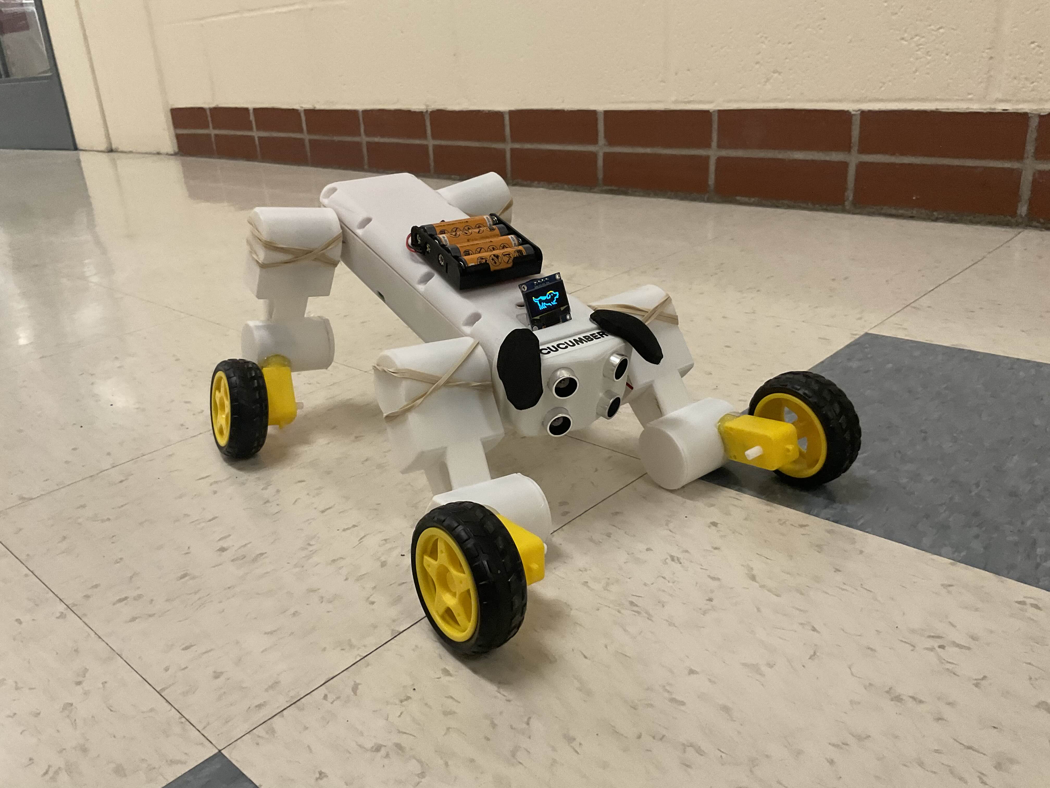
Cucumber is a Wi-Fi-controlled quadruped robot dog that follows you, poses on command, and barks and displays personality. After all, who would not enjoy a pet that you do not need to feed? (Except you do need to put in new batteries every now and then.)
What we did: We built Cucumber, a quadruped robot pet powered by the Raspberry Pi Pico W, designed to move, pose, follow people, and respond to user commands. It combines DC motors for locomotion, servos for expressive poses, ultrasonic sensors for autonomous following, an OLED display for visual feedback, and a speaker for synthesized dog sounds using DDS. A custom web interface hosted by the Pico W allows users to control movement, pose, sound, and mode over Wi-Fi. The entire system runs on dual-core concurrency with protothreads for smooth, real-time responsiveness.
Why we did it: Our goal was to create a robot that felt more like a companion than just a machine—something expressive, interactive, and fun. We wanted to apply microcontroller's concepts in a creative way that emphasized user engagement, real-time control, and physical behavior. This project challenged us to balance hardware constraints, concurrency, and usability, while giving us the opportunity to build a full-stack microcontroller system with personality.
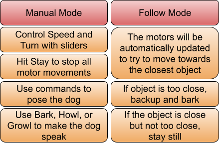
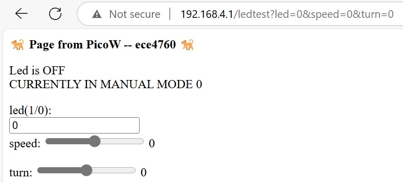
The dog is controlled via a webpage hosted by the Pico W. When in Manual Mode, the user can move the dog and give it commands for physical poses and audio clips. When in Follow Mode, the dog will attempt to move towards the closest object.
Cucumber was inspired by a combination of quadruped robotics platforms like Boston Dynamics' Spot and the designing robotic systems through the Raspberry Pi Pico W. We also drew inspiration from the Zoomer Robotic Dog Toy. Our goal was to create an expressive and interactive robot dog that could emulate companionship and real-time responsiveness. The team drew upon knowledge from embedded systems, control theory, and digital signal processing acquired in ECE 4760 and other courses.
Cucumber’s movement is controlled by:
Both components are controlled via Pulse Width Modulation (PWM), which rapidly switches a digital pin between HIGH and LOW to approximate analog power delivery. The key variable is duty cycle:
$$\text{Duty Cycle (%)} = \left( \frac{T_{\text{ON}}}{T_{\text{ON}} + T_{\text{OFF}}} \right) \times 100$$
where \( T_{\text{ON}} \) is the time the signal is HIGH and \( T_{\text{OFF}} \) is the time it is LOW.
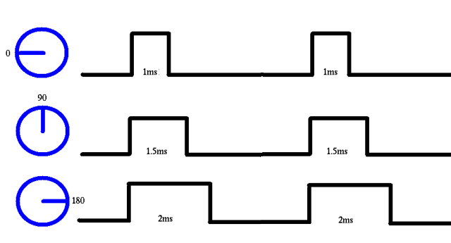
For a standard 50 Hz signal (period = 20 ms), servos like the MG996R interpret:
So, to convert angle to pulse width:
$$\text{Pulse Width (ms)} = 1.0 + \left( \frac{\text{Angle}}{180} \right) \times 1.0$$
This is then mapped to a PWM count based on the system clock frequency \( f_{\text{clk}} \), clock divider \( D \), and wrap value:
$$\text{PWM Count} = \text{Pulse Width (s)} \times \frac{f_{\text{clk}}}{D}$$
For example, with a wrap value of 20,000 and divider of 125:
$$\text{Count}_{90^\circ} = 1.5 \times 10^{-3} \times \frac{125 \times 10^6}{10^3} = 1875$$
Each servo on Cucumber uses this math to translate leg poses into accurate angular control.
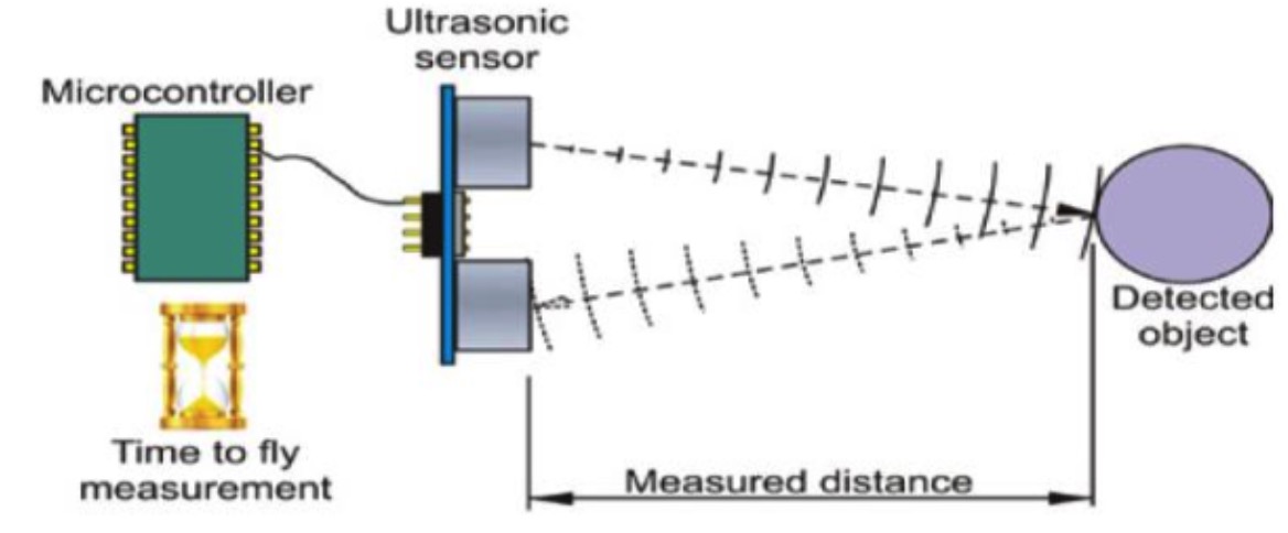
Cucumber uses HC-SR04 ultrasonic sensors to measure distance to nearby objects. The sensor emits a pulse and measures the round-trip time \( t \). The formula for distance:
$$d = \frac{t \cdot v}{2}$$
where \( v \approx 343\, \text{m/s} \). In microcontroller units using microseconds:
$$d(\text{cm}) = \frac{t(\mu s)}{58}$$
This conversion is used to read two distances: from the left and right sensor. The control algorithm compares them to decide movement:
      diff = left_distance - right_distance
      if diff > threshold:
          turn right
      elif diff < -threshold:
          turn left
      else:
          go forward
Cucumber uses DDS to synthesize audio (barks, growls, howls) by generating a digital waveform via a sine lookup table. Frequency of output signal is:
$$f_{\text{out}} = \frac{\Delta \cdot f_{\text{clk}}}{2^N}$$
where:
The output is:
      phase_accum += phase_incr;
      sample = sine_table[phase_accum >> 24];
To shape sound over time, we apply an amplitude envelope function:
\[ A(t) = \begin{cases} \frac{t}{T_{\text{attack}}} & \text{if } t < T_{\text{attack}} \\ 1 & \text{if } T_{\text{attack}} \le t < T_{\text{attack}} + T_{\text{sustain}} \\ 1 - \frac{t - (T_{\text{attack}} + T_{\text{sustain}})}{T_{\text{decay}}} & \text{otherwise} \end{cases} \]
This allows us to modulate the loudness of the audio in realistic bark/growl/howl patterns.
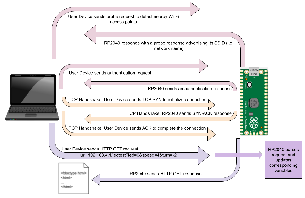
At a high level, sending Wi-Fi signals involves converting digital data into radio waves that can travel wirelessly and be received by other devices. The Pico W uses an CYW43439 chip to handle conversion of data into a 2.4 GHz radio wave that can be detected and connected to by other devices. From there, network communication is conducted using Transmission Control Protocol (TCP). Once verified, the user sends an HTTP GET request in the form of the URL. This is passed to the RP2040 which parses the data from the request, makes necessary variable updates, and sends the HTML data for the corresponding page. The user device and RP2040 will continue to send and receive GET requests and responses until the connection is closed.
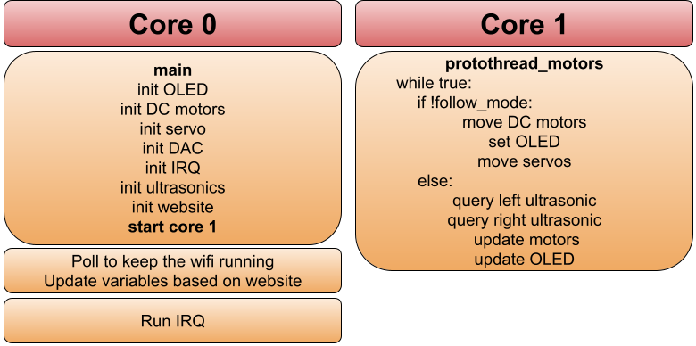
Cucumber uses a dual-core approach on the Raspberry Pi Pico W:
The system uses protothreads for cooperative multitasking, enabling servo sweeps, sound generation, and sensor reads in parallel without true preemption.
Our DC motor system operated without encoders, making it an open-loop system. This limited our ability to achieve precise forward motion, as we couldn't track or correct for differences in wheel rotation. We made the decision to not complicate our hardware further and accept this imprecision in motor movement in manual mode. We relied on software to process data from the ultrasonic sensors and dynamically adjust motor power during follow mode. While adding encoders would have improved precision, it would have introduced additional hardware complexity and GPIO requirements, so we chose to keep the system simple and manage direction purely through feedback.
When implementing audio, we explored several options for generating sound. Initially, we considered processing a pre-recorded sound bit and passing it directly to the speakers. However, we chose to use Direct Digital Synthesis (DDS) along with a DAC which offloaded the signal conversion from the software to the hardware. One issue we encountered was low speaker volume. We opted for a hardware fix by adding an amplifier rather than complicating the software signal further.
At the beginning of the project, we considered adding a potentiometer and button for user control alongside the web interface. This control scheme would have been very similar to Lab 2, with the OLED displaying options, the potentiometer being used to move between them, and the button being used to select. However, this idea became impractical for several reasons. First, any robot movement during motor operation would physically shift the controls away from the user, reducing usability. Second, we used all available GPIOs on the board, leaving no room for the ADC or button. Most importantly, the web interface was implemented more quickly and effectively than anticipated, rendering the physical controls unnecessary. As a result, we relied fully on software via the Wi-Fi access point for all user control.
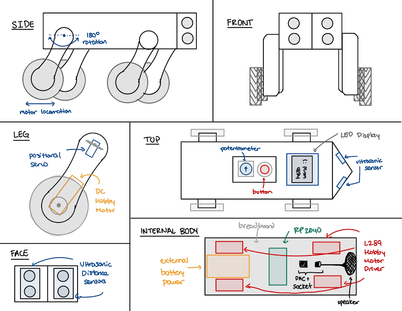
The preliminary design for Cucumber illustrated in the image above. Cucumber can move back and forth using motor wheels, perform different poses using a positional servo on each leg joint, detect and interact with users using ultrasonic sensors, and interact using a speaker, OLED screens, and buttons. Instead of having two joints per leg like a real dog, we opted for one joint and a DC motor wheel to take care of locomotion. This simplifies movement for the robot dog and makes the project more realistic given the 4-week time constraint.
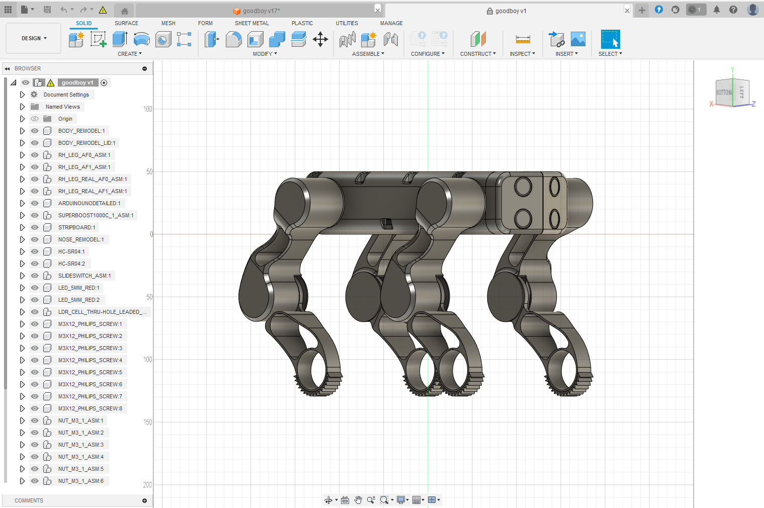

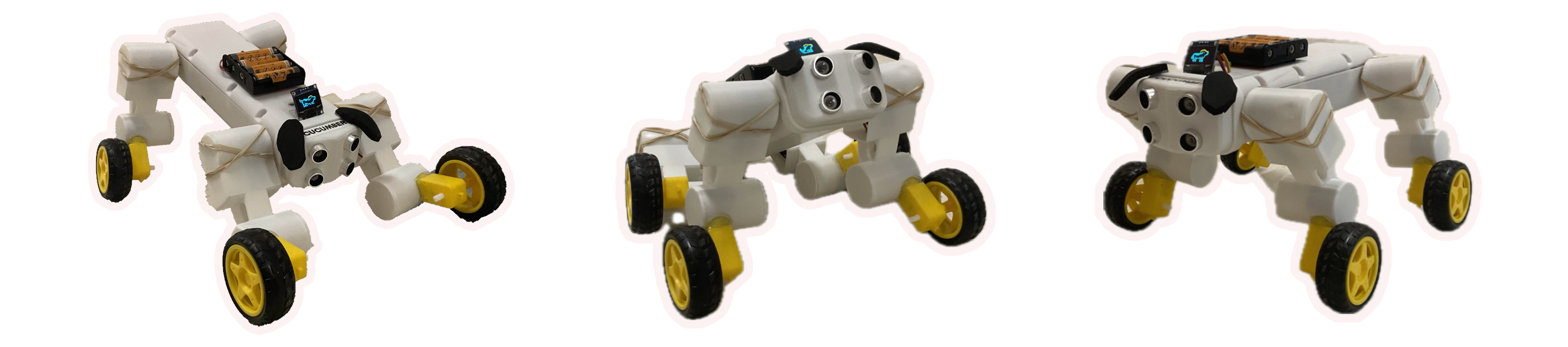
The mechanical CAD design of Cucumber the robot dog is primarily based off of an existing design for Goodboy, an Arduino robot dog project inspired by the design of Boston Dynamics' Spot robot. Several key modifications were made to the original design in Fusion 360 to fit our project's hardware requirements. The biggest modification was in the leg joint, which now contains one servo and a gearbox motor with a wheel instead of two servos like the original design. Additionally, we elongated the dog's body to have more space for components like a speaker and to ensure a 180 degree range for each leg joint. The nose was slightly remodled so it has a lip over the body, allowing for easier removal and debugging.
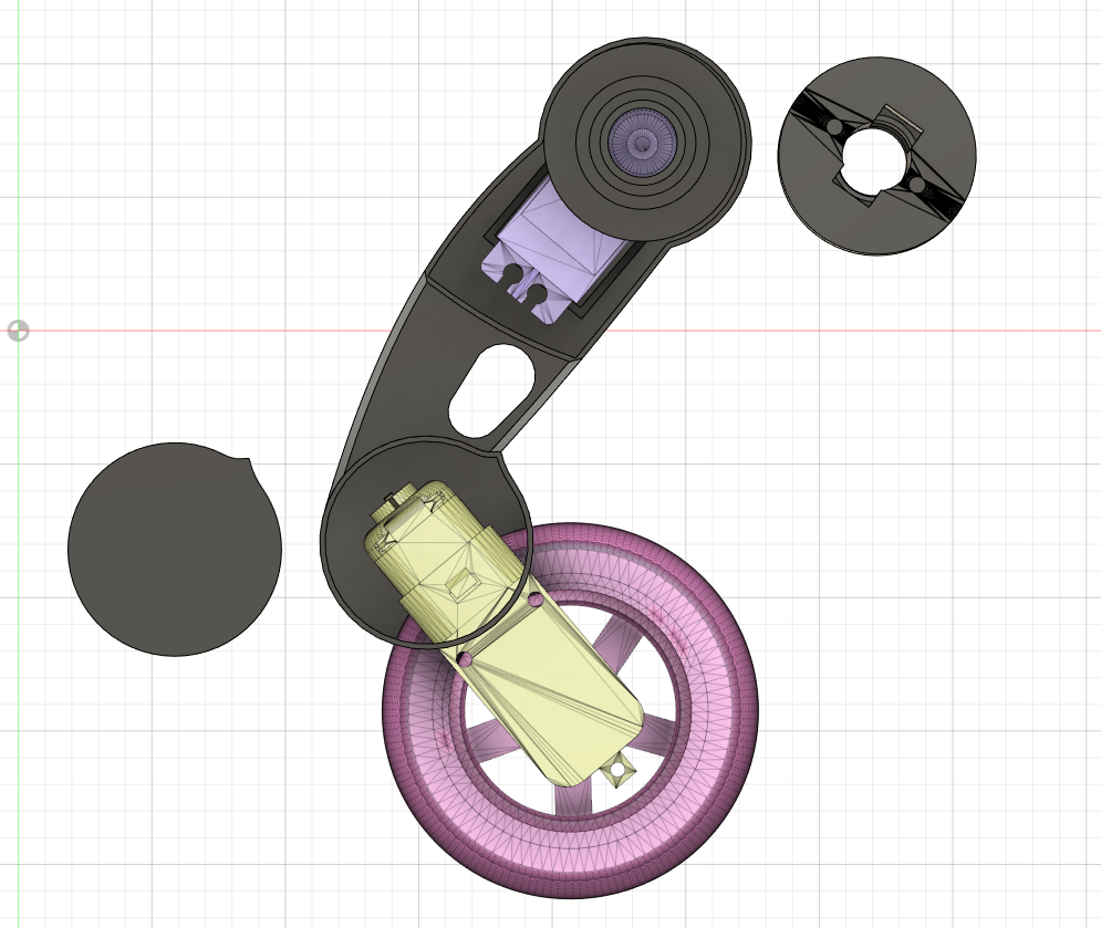
Looking closer at the leg, a servo is embedded at the top of the leg near the body attachment joint and a gearbox motor is friction fit into the bottom of the leg or the kneecap. The rotor of the gearbox motor is then connected to a plastic wheel, providing traction for locomotive movement. A custom shoulder pin is designed to exactly fit the servo horn, providing a secure mount to the servo when attached to the body of the dog. This pin provides the necessary range of motion for the leg joint, allowing the dog to perform poses like 'sit' and 'down'. The leg joint is designed to be modular, allowing for easy replacement of components if needed. A GIF showing the motion of the leg joint with the custom pin is shown below.
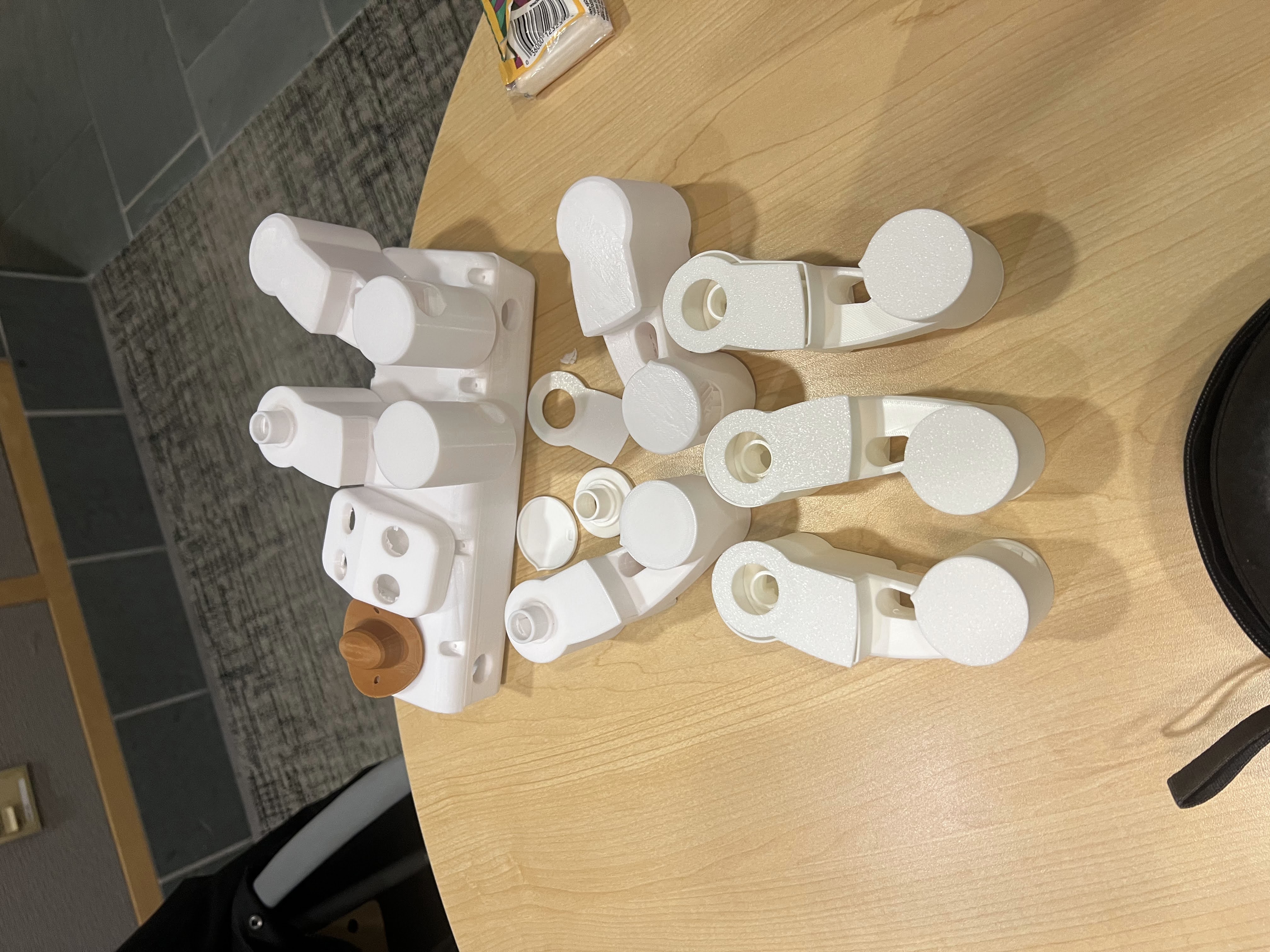
Once CAD of the dog was completed, models were exported into STLs and parts were printed using white PLA filament. The image below shows all the printed parts, including the body, legs, and head. Standard 3D printing settings were used, including a 20% infill and 0.2mm layer height.
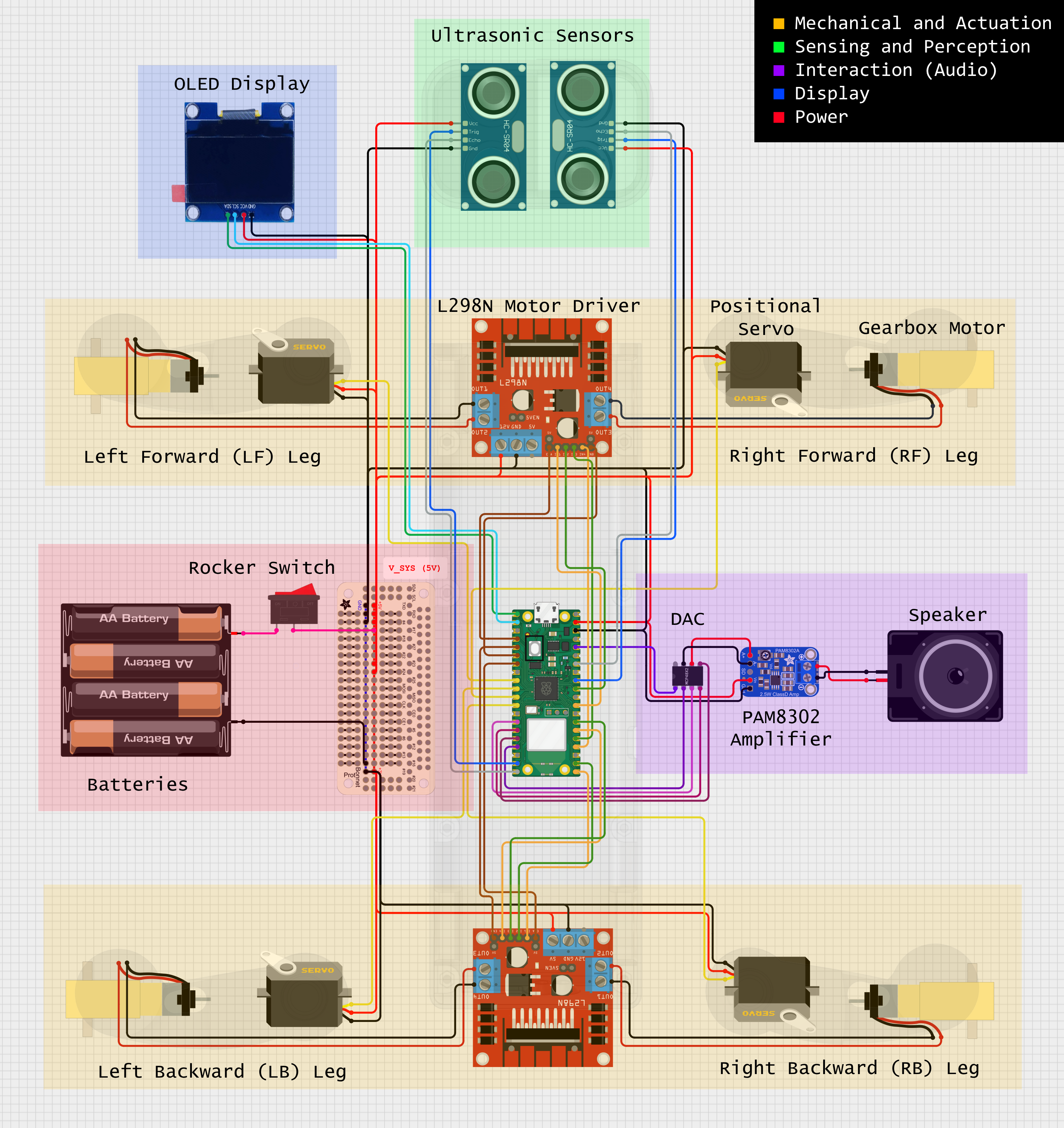
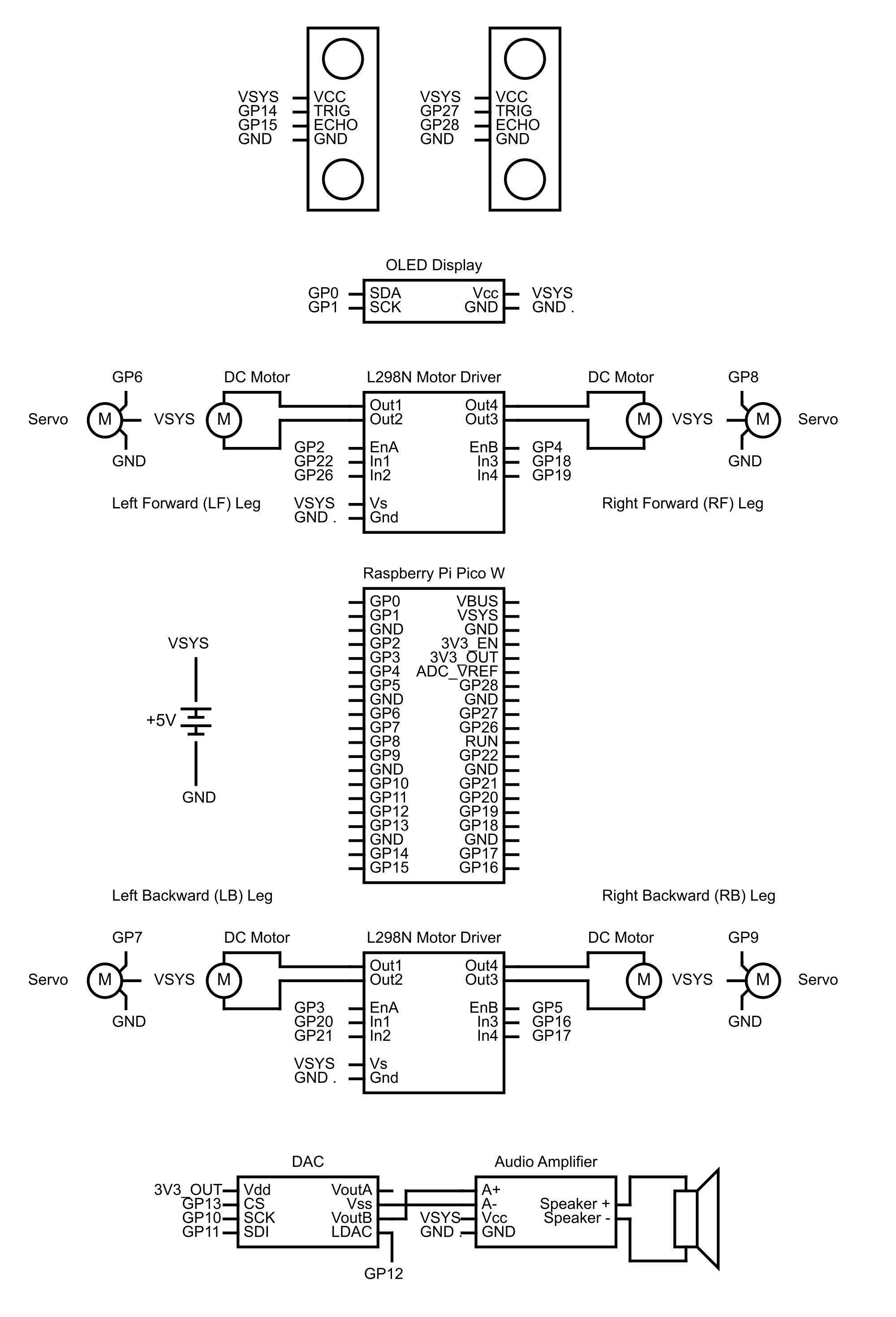
The final breadboard and circuit diagram above shows the connections between the Raspberry Pi Pico W and the various components used in the project. There are five main sections of electrical hardware: Mechancial and Actuation, Sensing and Perception, Audio, Display, and Power. Each section is highlighted with a certain color in the diagram above. In terms of overall components, the robot dog contains:
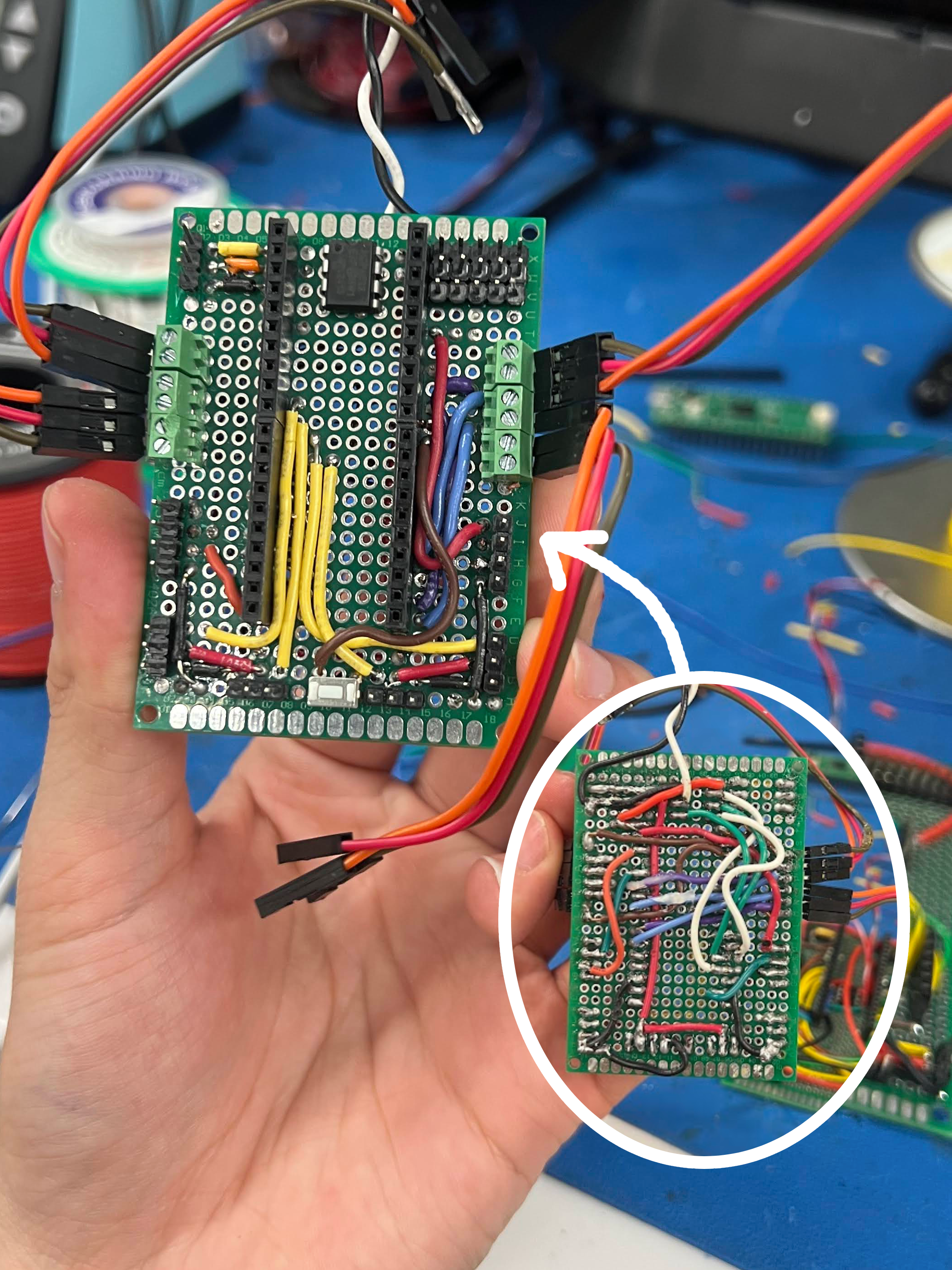
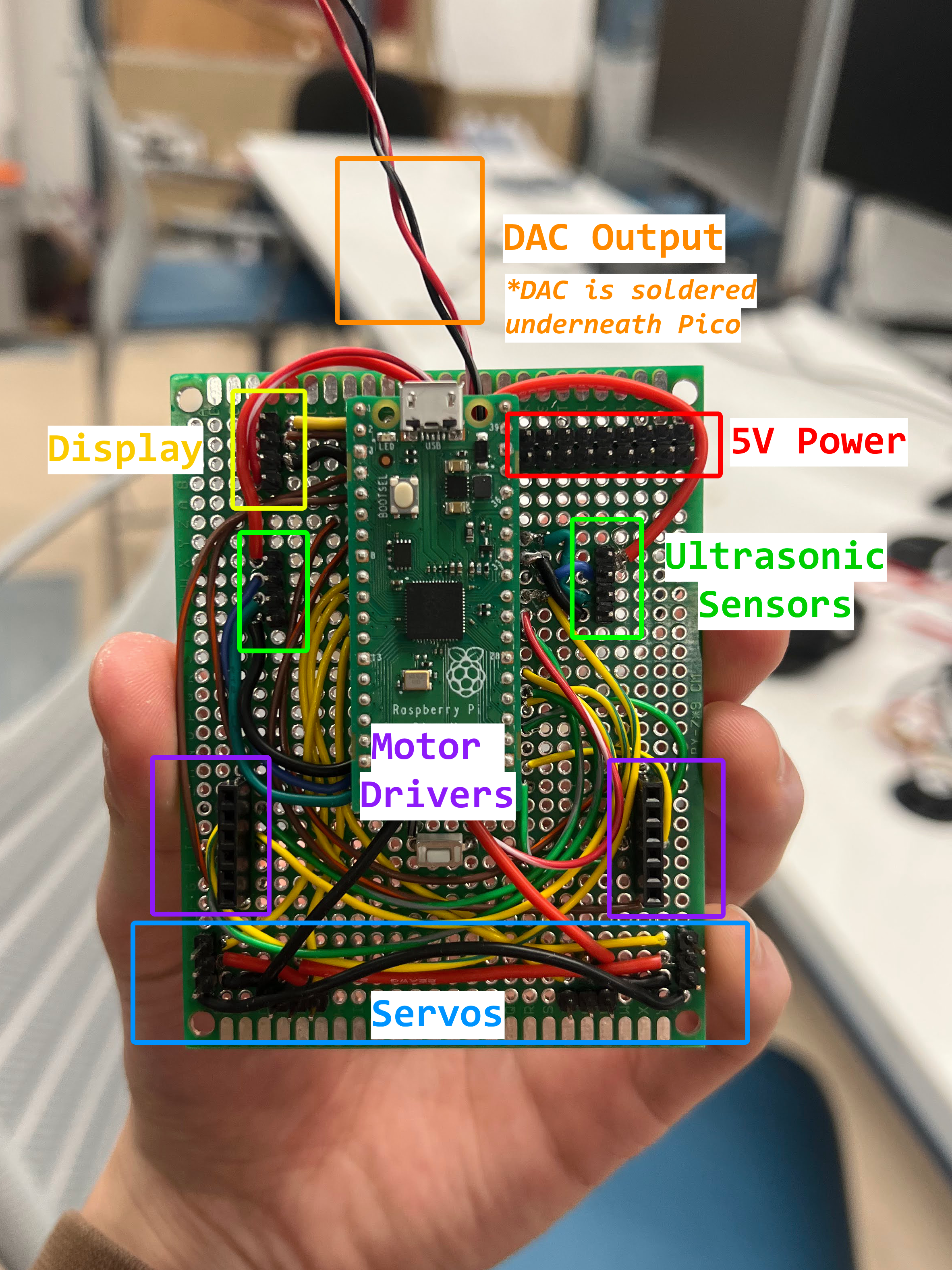
All components are interconnected togehter on a custom solderboard, which is then connected to the Pi Pico W. The solderboard is designed to be modular, allowing for easy replacement of components if needed. The images above show the initial failed solderboard and the final solderboard design. The first iteration was scrapped due to shorts throughout the board, most likely because wires were soldered on both sides of the solderboard. Male and female header pins are used to interconnect various components and allow for modularity while debugging.
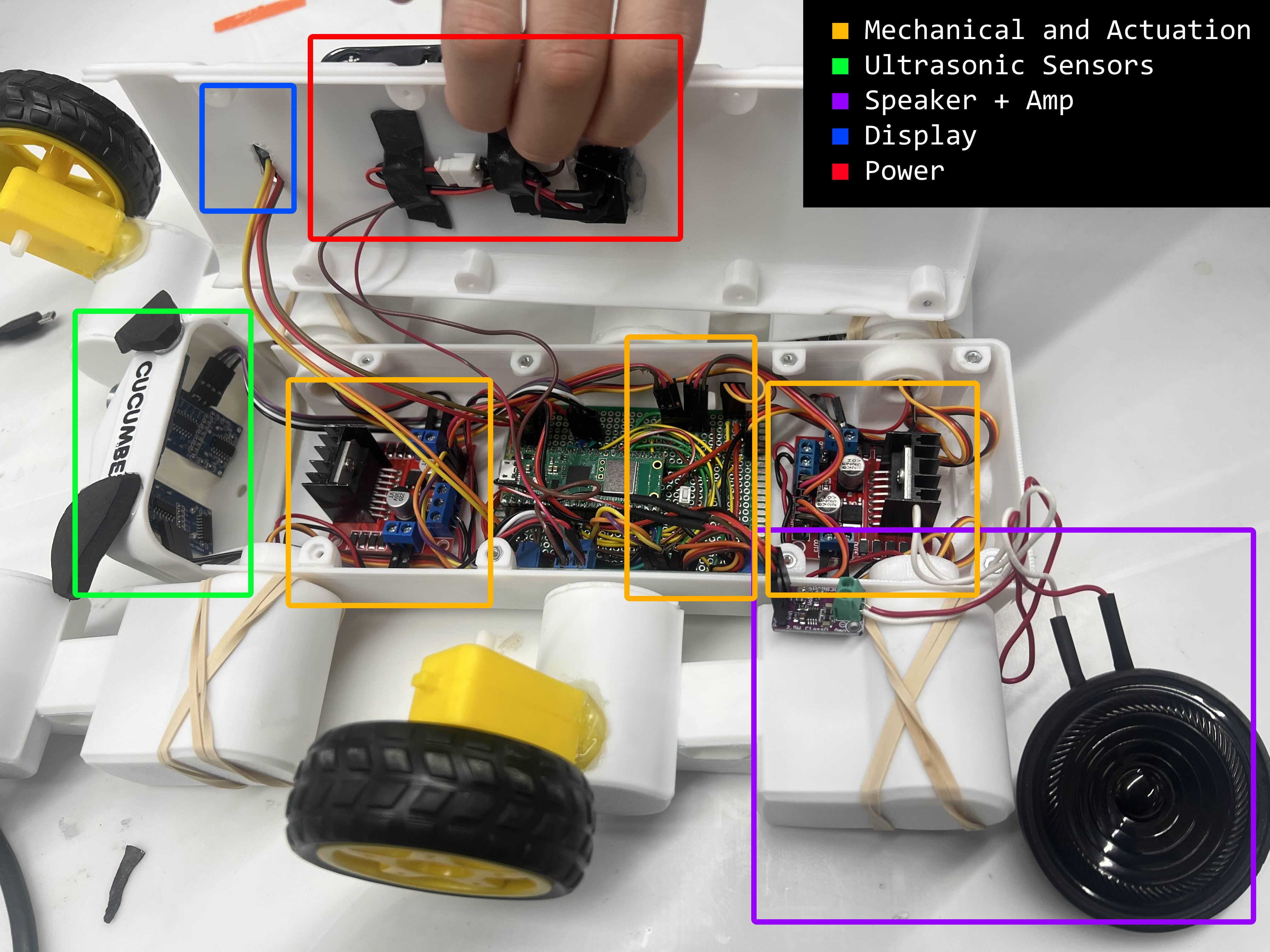
The image above shows the internal electronics of Cucumber stored inside the body, with all components connected to the custom solderboard. It's a tight fit but most components are able to fit within the body nicely. Some components are not visible due to being above the lid (display and battery) or being embedded within each leg joint (servo and DC motor).
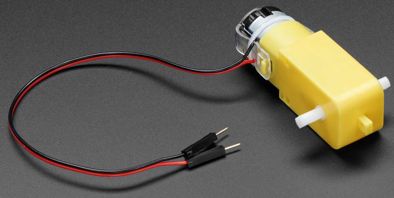
Cucumber uses four 6V DC gearbox motors—one per leg—for forward and backward motion. These motors are mounted at the knees of each leg, driving wheels that enable the dog to move in a differential drive pattern.The DC motors are generic TT DC gearbox motors with a gear ratio of 1:48. These motors are rated for 3~6V making them a good fit for power from four AA batteries. There is some variation in each motor due to the lack of encoders, speed control or position feedback. Regardless, these motors were chosen for their cheap price, simple accessibiltiy with motor drivers, and matching power requirements.
Motor Controller Modules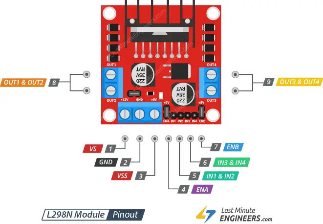
Each pair of motors is controlled by a dual-channel L298N motor driver. These drivers receive logic-level signals from the Raspberry Pi Pico W and translate them into higher-current outputs suitable for driving the motors. They are mounted inside the body of the dog near the front joints and the back joints. The motor driver provides control over motor speed using PWM and control over spin direction using an internal H-Bridge. Pulse Width Modulation (PWM) sends a series of ON-OFF pulses - the average voltage is proportional to the width or duty cycle of the pulses. The higher the duty cycle (larger pulse width), the higher the average voltage is applied to the DC motor therefore increasing the motor speed. The shorter the duty cycle, the lower the motor speed. The EN pin on each motor driver is pulsed using PWM. The H-Bridge controls the spin direction by changing the polarity of the input voltage. These are controlled by the InA and InB pins on the motor driver. Battery power is applied to the Vs and GND pins to supply the DC motors. Note that each driver supports two motor inputs, thus we used two drivers for four motors overall.
Positional Servos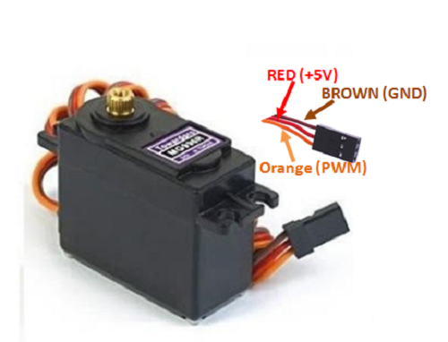
Each leg includes a single positional servo at the top joint (shoulder), providing lift and pose articulation. They are mounted using custom-designed brackets. The positional servos used are MG996R robot servos with 180 degrees of rotation. It weighs 55g and has a torque of 9.5kg at 4.8V, and a speed of 0.17 sec/60 deg making it a good fit for each shoulder joint. The operating voltage ranges from 4.8V to 6V, making it usable with four AA batteries. Positional servos provide feedback for the controller to monitor it's position on the movement arc over the control wire, allowing movement to precise locations and angles depending on the pulse length. This is done using an internal potentiometer and integrated circuit within the body of the servo. Using PWM, we can control the pulse width output on the GPIO pin and therefore the angle of each servo. More details are explained in the software design section.
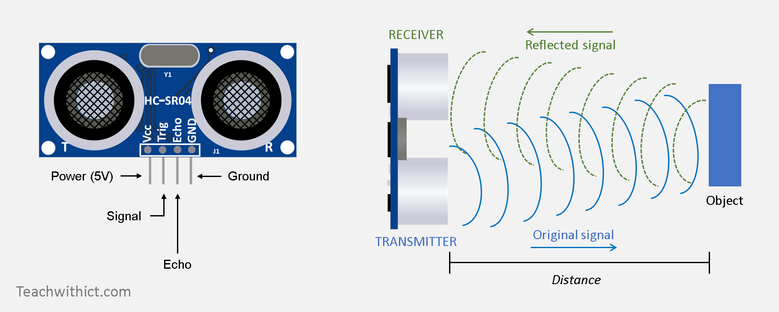
Two HC-SR04 ultrasonic distance sensors mounted at the front of the robot measure distances to nearby objects. which take in DC 5V and have an ultrasonic frequency of 40 kHz. It has a minimum range of 2cm and a maximum range of 400cm, with an accuracy of 3mm and a measuring angle of <15 degrees. Ultrasonic sensors measure the distance to an object by using a transducer to send and receive ultrasonic pulses that relay information about an object's proximity. A sound wave at a frequency above human hearing range is sent out using the Trig pin and then the Echo pin listens for the reflected signal. The software subsection describes the process of converting this information into recordable measurements. These sensors form the core of the dog’s "follow" behavior by detecting proximity and relative position of a human hand or object in front of it.
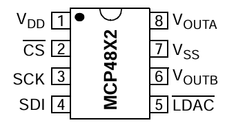
The DAC used is the same one from Lab 1, the MCP4802 Digital to Analog Converter. The DAC is responsible for converting digital signals from the RP2040 to analog signals for the audio socket. The DAC interfaces with the RP2040 using SPI, which enables high-speed, synchronous data transfer between the microcontroller and the DAC. The communication between the RP2040 and the MCP48X2 DAC is achieved by transmitting 16-bit data packets that represent the amplitude values of the synthesized waveform at specific time intervals. The SPI interface is configured with a clock polarity of 0 and a clock phase of 0, following SPI Mode 0. In this configuration, the SPI clock (SCK) idles at a low logic level, and data is sampled on the rising edge of the clock signal while being shifted out on the falling edge. This ensures reliable data transmission and precise timing, which are critical for maintaining audio signal integrity. The 16-bit data sent to the DAC includes both control bits and the actual digital value that dictates the voltage level of the analog output.
Amplifier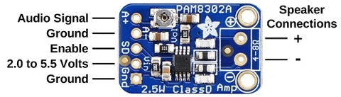
The amplifier used in this project is a PAM8302 audio amplifier, capable of delivering 2.5 watts into a 4-8 ohm impedance spaker. It contains built in thermal and over current protection, as well as capacitors on speaker outputs for full differentiation. The output is a high frequency 250 kHz square wave PWM that is then averaged out by the speaker coil. The A+ and A- are connected to the DAC output, amplifier power is supplied by Vsys of the Pico, and the speaker connection is directly connected to the speaker.
Speaker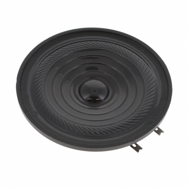
The speaker used is a K 64 WPT 8 ohm mono speaker. It is rated for 2-3 watts of power, making it a good fit for the amplifier used. We initally connected the speaker directly to the Pico's GPIO pin but found that the speaker output was too quiet.
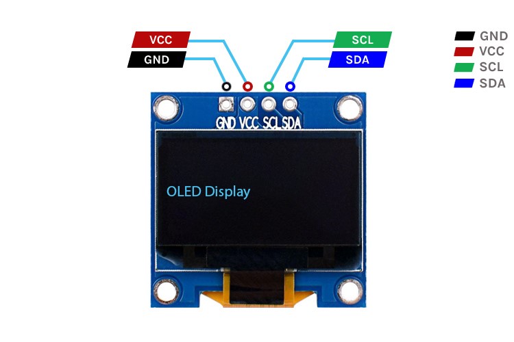
The OLED screen used is a 0.96 inch 128x64 dichrome SSD1305 display which uses I2C to communicate display information. Due to its low price, the display has two hardcoded yellow and blue regions of the display that cannot be changed. The display supports 3.3V-5V of power and has a back light. It displays pixelated emoji faces and labels based on the robot’s current pose or sound state. The screen uses the SSD1306 driver and provides visual cues for different poses in manual mode. It also shows range data and debug text in following mode.
The main power supply of the robot dog is four AA batteries, providing 6 volts and around 2500-3000 mAh of power at full charge. We choose to go with four AA batteries because the voltage supplied matched the needs of most of our other electrical components and wouldn't risk overvoltage damage. Batteries also provide the advantage of being replacable, therefore we could swap them out as needed any time. A rocker switch was soldered to the positive end of the battery holder to provide easier access for powering on and off. The system is designed to operate for ~30 minutes continuously on fresh alkaline batteries.
Power Distribution BoardPower from the battery supply was routed to a custom solderborad that simply interconnects all electrical components that need power together. Battery power is shared with Vsys power on the Pico, providing power to the microcontroller itself as well as other electrical components. This board includes pin headers and voltage lines routed from the main battery pack.
| GPIO | Function |
|---|---|
| 0 | Screen SDA |
| 1 | Screen SCL |
| 2 | Left Forward (LF) Motor En |
| 3 | Left Backward (LB) Motor En |
| 4 | Right Forward (RF) Motor En |
| 5 | Right Backward (RB) Motor En |
| 6 | LF Servo |
| 7 | LB Servo |
| 8 | RF Servo |
| 9 | RB Servo |
| 10 | DAC SCK |
| 11 | DAC MOSI |
| 12 | DAC LDAC |
| 13 | DAC CS |
| GPIO | Function |
|---|---|
| 14 | Ultrasonic Left Trig |
| 15 | Ultrasonic Left Echo |
| 16 | RB Motor InA |
| 17 | RB Motor InB |
| 18 | RF Motor InA |
| 19 | RF Motor InB |
| 20 | LB Motor InA |
| 21 | LB Motor InB |
| 22 | LF Motor InA |
| 23–25 | Unavailable |
| 26 | LF Motor InB |
| 27 | Ultrasonic Right Trig |
| 28 | Ultrasonic Right Echo |
The GPIO pinout table above shows the connections between the Raspberry Pi Pico W and the various components used in the project. All accesible GPIO pins were utilized by the end of this project. Note that some GPIO pins require certain communication protocols available. For example, the OLED screen requires I2C and the DAC requires SPI, which are only available on certain GPIO pins.
The mechanical and actuation subsystem is responsible for controlling the movement of Cucumber. It uses Pulse Width Modulation (PWM) to control the speed of direction of the DC motors and the angle of the servos. Background math has been previously described in the High Level Design section. Code implementation is largely based off of Lab 3 PID control of a 1D helicopter, specifically the PWM demo code.
The PWM wrap handler function, on_pwm_wrap(), is responsible for sending both signals to the motors and servos concurrently. This is done by keeping track of PWM slices for each device in their structure definition. DC motors pulse at 1 kHz while servo motors pulse at 50 Hz as required by servo specification.
| GPIO | 0 | 1 | 2 | 3 | 4 | 5 | 6 | 7 | 8 | 9 | 10 | 11 | 12 | 13 | 14 | 15 |
|---|---|---|---|---|---|---|---|---|---|---|---|---|---|---|---|---|
| PWM Channel | 0A | 0B | 1A | 1B | 2A | 2B | 3A | 3B | 4A | 4B | 5A | 5B | 6A | 6B | 7A | 7B |
| GPIO | 16 | 17 | 18 | 19 | 20 | 21 | 22 | 23 | 24 | 25 | 26 | 27 | 28 | 29 | ||
| PWM Channel | 0A | 0B | 1A | 1B | 2A | 2B | 3A | 3B | 4A | 4B | 5A | 5B | 6A | 6B |
The Pico W only has 8 independent PWM generators or slices and each slice has two channels (A and B), making a total of 16 PWM channels. Since we are pulsing 4 motors and 4 servos independently, our PWM requirements are fortunately exactly met.
Custom struct type motor_t was created to easily keep track and abstract variables for each motor and includes:
Referring back to the L298N motor driver, the spinning direction of the motor can be controlled by applying logic high or logic low to the InA or InB inputs. The table below shows the combinations and their outcomes. These motor directions are controlled by motor_forward(), motor_backward(), and motor_stop().
| Input A | Input B | Spinning Direction |
|---|---|---|
| Low(0) | Low(0) | Motor OFF |
| High(1) | Low(0) | Forward |
| Low(0) | High(1) | Backward |
| High(1) | High(1) | Motor OFF |
motor_forward(speed) and motor_backward(speed) take in a speed parameter from 0 to 30. This 0 to 30 scale corresponds to configuring a duty cycle of 3000 to 5000 on the pwm wrap function. 3000 was choosen as the minimum since this is the minimum duty cycle required to spin the DC motor at a low rate.
One overall function, move_all_motors(speed, turn), controls all four motors using a speed and turn variable. A speed of 10 refers to forward motion and a speed of -10 refers to backwards motion. A turn variable of 10 refers to turning right and a turn variable of -10 refers to turning left. These parameters are controlled by user input on the web interface. The code snippet below shows the math used to translate speed and turn variables into numbers for the motor_forward() and motor_backward() functions.
    // Max and min speeds are -20 to +20
    int left_speed = speed + turn*2;
    int right_speed = speed - turn*2;
    printf("Left Speed: %d, Right Speed: %d\n", left_speed, right_speed);

    // Clamped
    left_speed = (left_speed < -30) ? -30 : (left_speed > 30) ? 30 : left_speed;
    right_speed = (right_speed < -30) ? -30 : (right_speed > 30) ? 30 : right_speed;
Another custom struct type servo_t was also created to easily keep track and abstract variables for each motor. It includes the following elements:
The function servo_angle() takes in a pointer to a servo_t struct and an angle integer from 0 to 180 degrees. It then maps this angle integer to a duty cycle of 500 to 2400 that updates the servo pwm duty cycle on the pwm wrap function. These values were choosen based off the background math and adjusted after trial and error testing on a physical servo.
To move all four servo motors concurrently, the function set_all_servos() is used and takes in an array of four integers. Each integer corresponds to the desired angle for one servo. The current angle of each servo is compared to its desired angle, and then each servo is stepped independently by 1 (increment or decrement by 1) until it reaches it's desired angle in a while loop. This ensures that all servos move concurrently at the same time and prevents instability when changing poses. This function is also the basis for the pose functionality, as each pose is defined by an array of 4 angles. The code snippet below includes the logic used in set_all_servos().
    // Get current angles for each servo
    for (int i = 0; i < 4; i++) {
        int current_angle = map(servos[i]->duty, 500, 2400, 0, 180);
        if (servos[i]->inv) current_angle = 180 - current_angle;
        current_angles[i] = current_angle;
    }

    // Step each servo independently to its target
    while (!done) {
        done = true;
        for (int i = 0; i < 4; i++) {
            if (current_angles[i] < target_angles[i]) {
                current_angles[i]++;
                done = false;
            } else if (current_angles[i] > target_angles[i]) {
                current_angles[i]--;
                done = false;
            }
            servo_angle(servos[i], current_angles[i]);
        }
        sleep_ms(10);
    }
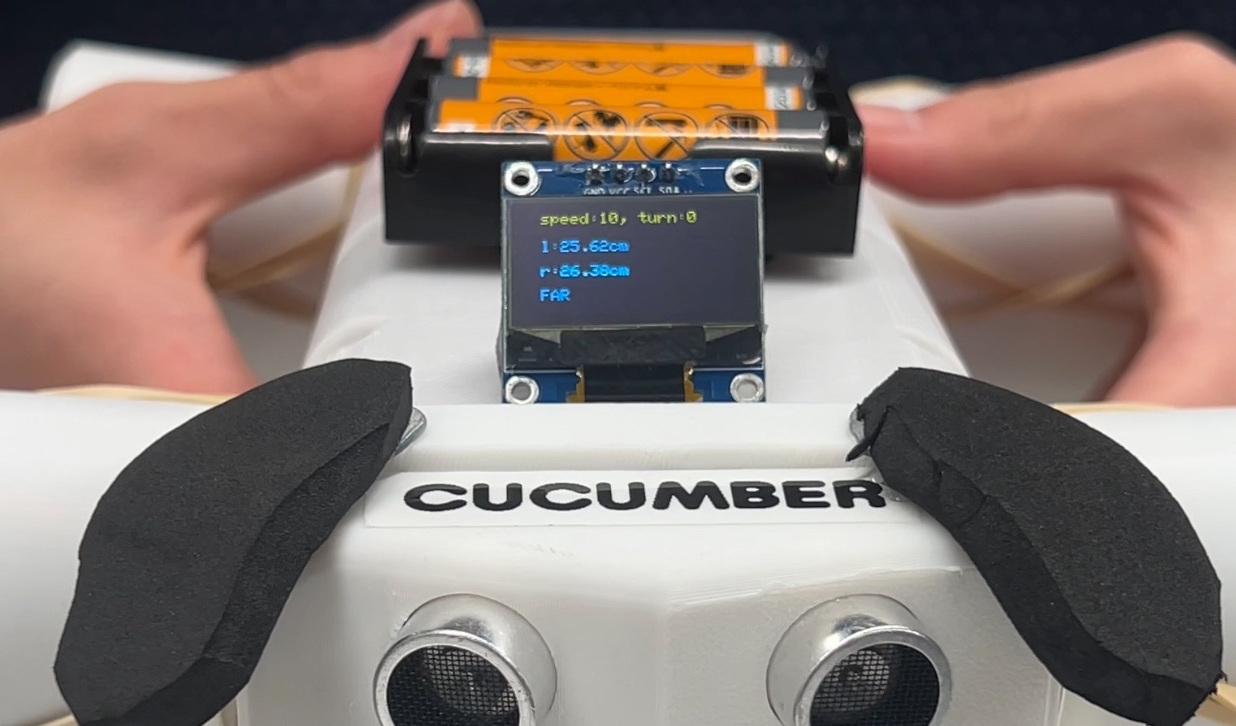
Cucumber uses two HC-SR04 ultrasonic sensors—one mounted on the left and one on the right of its "face"—to measure proximity in Follow Mode. These readings allow the robot to determine both distance and direction to a nearby target, such as a human hand.
Each sensor emits a short 40 kHz pulse and measures the time until it receives the echo. This "time of flight" allows calculation of distance using the formula:
\( d = \frac{v \cdot t}{2} \) or \( d(\text{cm}) = \frac{t(\mu s)}{58} \)
Where \( v = 34300 \, \text{cm/s} \) is the speed of sound in air and \( t \) is the round-trip time in microseconds. The division by 2 accounts for the return trip of the wave.
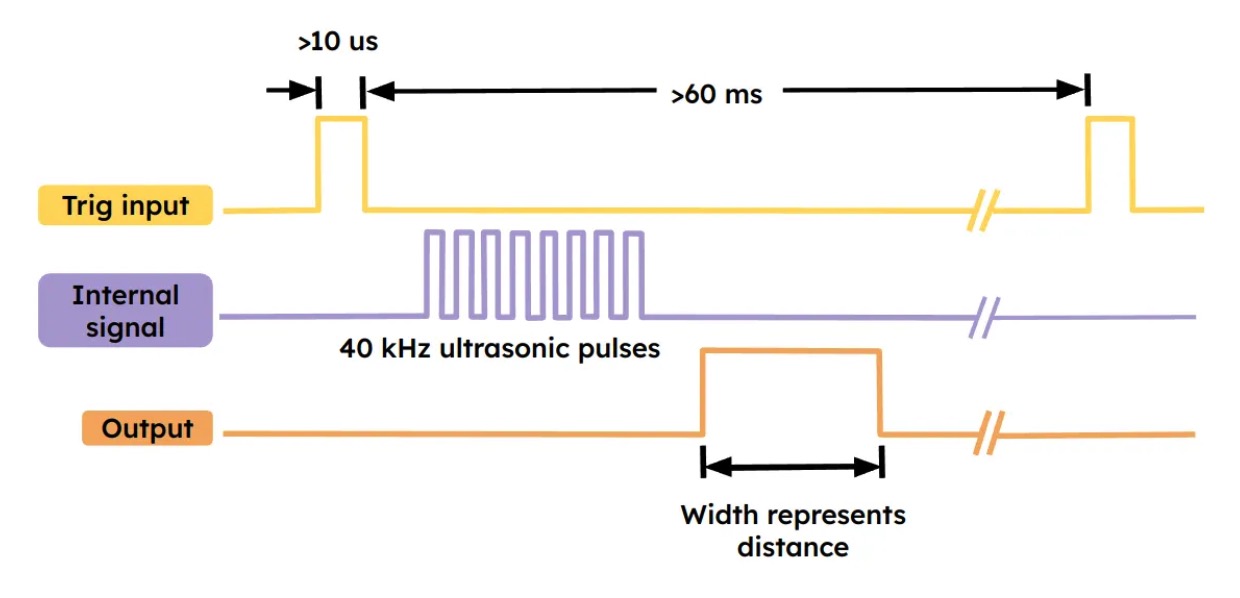
To initiate a reading, the microcontroller sends a 10 µs HIGH pulse to the sensor's trigger pin. The sensor responds by emitting 8 ultrasonic pulses and sets its echo pin HIGH until the echo returns.
The pulse width of the echo output is proportional to the distance. This timing relationship is visualized below:
The function get_distance_cm() triggers the sensor and computes the echo time using the Pico's
system clock. To prevent blocking system-wide behavior, we use save_and_disable_interrupts()
for critical timing measurement:
      // Measure distance from trigger/echo pair
      float get_distance_cm(int trig_pin, int echo_pin) {
          // Trigger 10 us pulse
          gpio_put(trig_pin, 0); busy_wait_us(2);
          gpio_put(trig_pin, 1); busy_wait_us(10);
          gpio_put(trig_pin, 0);

          // Time echo pulse duration
          while (!gpio_get(echo_pin)) { ... }
          absolute_time_t echo_start = get_absolute_time();
          while (gpio_get(echo_pin)) { ... }
          absolute_time_t echo_end = get_absolute_time();

          // Calculate distance
          int64_t pulse_us = absolute_time_diff_us(echo_start, echo_end);
          return pulse_us / 58.0f;
      }
In follow mode, Cucumber constantly polls both sensors and determines movement based on distance differential:
      static void hand_follow_decide(float left_cm, float right_cm) {
          speed_field = 0;
          bool have_left  = (left_cm  > 0);
          bool have_right = (right_cm > 0);
          float nearest = -1.0f;

          if (have_left && have_right && fabsf(left_cm - right_cm) < SENSOR_TOL)
              nearest = 0.5f * (left_cm + right_cm); // average
          else if (have_left && have_right)
              nearest = (left_cm < right_cm) ? left_cm : right_cm;
          else if (have_left)
              nearest = left_cm;
          else if (have_right)
              nearest = right_cm;

          float diff = left_cm - right_cm;

          if (left_cm <= RANGE_TOO_CLOSE && right_cm <= RANGE_TOO_CLOSE) {
              speed_field = -high_speed;
              turn_field  = 0;
              SOUND_STATE = 0; // bark
          } else if (!have_left) {
              speed_field = 0;
              turn_field  = +high_turn;
          } else if (!have_right) {
              speed_field = 0;
              turn_field  = -high_turn;
          } else if (diff > SENSOR_TOL) {
              speed_field = +high_speed;
              turn_field  = +high_turn;
          } else if (diff < -SENSOR_TOL) {
              speed_field = +high_speed;
              turn_field  = -high_turn;
          } else if (nearest == -1.0f || nearest > RANGE_TOO_FAR) {
              speed_field = high_speed;
              turn_field  = 0;
          } else if (nearest != -1.0f && nearest <= RANGE_HIGH || nearest >= RANGE_TOO_CLOSE) {
              speed_field = 0;
              turn_field  = 0;
          }
      }
The following thread snippet runs continuously when follow mode is active. It reads both
ultrasonic sensors, passes data to the hand_follow_decide() logic, and prints
the interpreted command to the OLED:
      if (follow_mode) {
          left_distance = get_distance_cm(LEFT_TRIG_PIN, LEFT_ECHO_PIN);
          right_distance = get_distance_cm(RIGHT_TRIG_PIN, RIGHT_ECHO_PIN);
          hand_follow_decide(left_distance, right_distance);
          print_word(...); // show distances on OLED
          sleep_ms(500);
      }
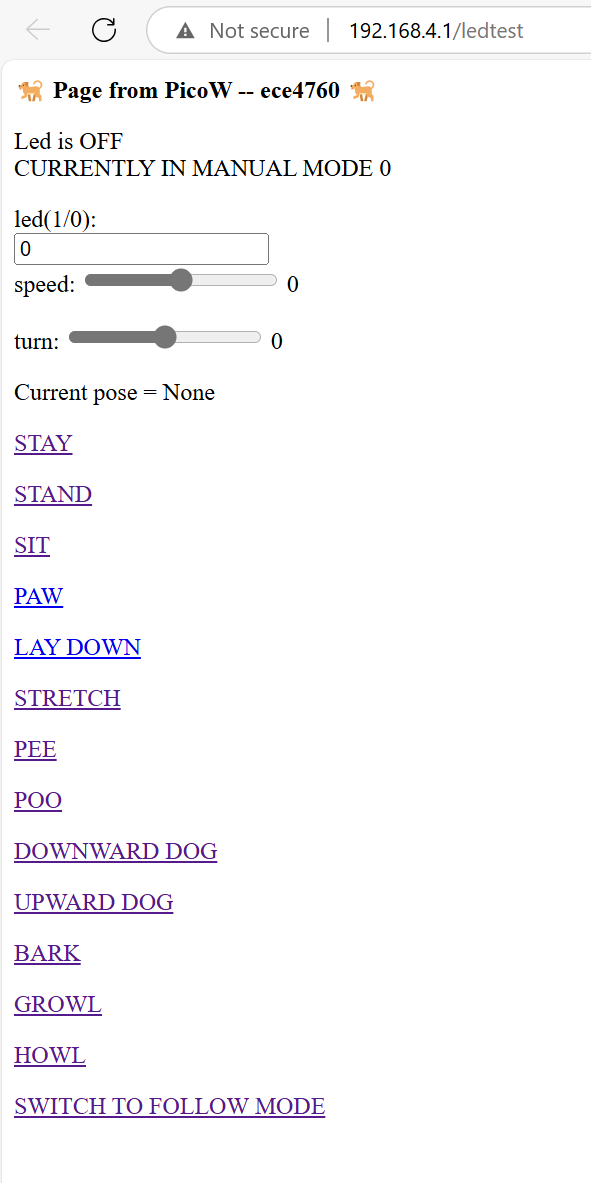
The user interacts with Cucumber through a local Wi-Fi access point hosted directly by the Raspberry Pi Pico W. The webpage design was modeled off the PicoW demo code and Bruce’s access point control panel code. The code initializes the network stack using the pico_cyw43_arch library and listens for incoming connections on a specified port using a TCP server. When the user adjusts a slider or toggles the LED, a 'form' on the website is submitted, pushing the new values to the url as shown in the image below.
The server parses the URL parameters using string parsing (e.g., sscanf), extracting variables like
speed, turning rate, pose, and mode. These values update shared global variables on the Pico. The control thread
then reads those updated variables and sends corresponding PWM signals to the motors and servos.
For example:
The pose buttons act like hyperlinks. Each time you click a pose (e.g., "SIT"), it sends a new URL with an updated pose parameter:

Physical result: When the "SIT" pose is selected:
pose_name variable is updated to "sit".set_all_servos() function is called, sending new PWM angles to the shoulder servos.The same approach is used for switching between manual mode and follow mode. The "Switch to Follow Mode" button sends a different URL:
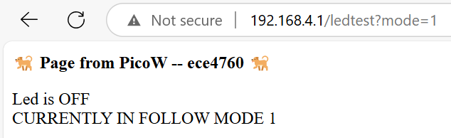
Physical result: Upon switching to follow mode:
follow_mode is set to true in the global state.
All interactions happen in real-time with no page reload required. Since the system uses
cooperative protothreads, motor motion, servo updates, DAC audio output, and webpage
interaction can all happen concurrently without blocking each other.
We used an OLED display for adding character to the dog via the poses diplayed above. Each pose is a 128x64 pixel drawing that is saved as a bitmap in the code. The pixel data is transmitted to the OLED using the I2C protocol. The screen is capable of also showing real-time debug text during Follow Mode.
For each predefined dog pose (e.g., sit, lay, stretch), we store a 1024-byte bitmap (128
× 64 pixels / 8 bits per byte). These are drawn using the draw_bitmap_fullscreen()
function, which iterates over each page of 8 pixels vertically and 128 horizontal columns to
fill the screen with pixels directly from the bitmap array.
     void draw_bitmap_fullscreen(ssd1306_t *disp, const uint8_t *bitmap) {
         for (int page = 0; page < 8; page++) {
             for (int col = 0; col < 128; col++) {
                 uint8_t byte = bitmap[page * 128 + col];
                 for (int bit = 0; bit < 8; bit++) {
                     if ((byte >> bit) & 0x01) {
                         ssd1306_draw_pixel(disp, col, page * 8 + bit);
                     }
                 }
             }
         }
     }
This drawing routine is wrapped by the helper function oled_show_pose(const uint8_t *bmp),
which clears the screen and then displays the pose. The OLED is updated immediately using
ssd1306_show(), which writes the entire screen buffer to the hardware using a
multi-byte I2C burst write.
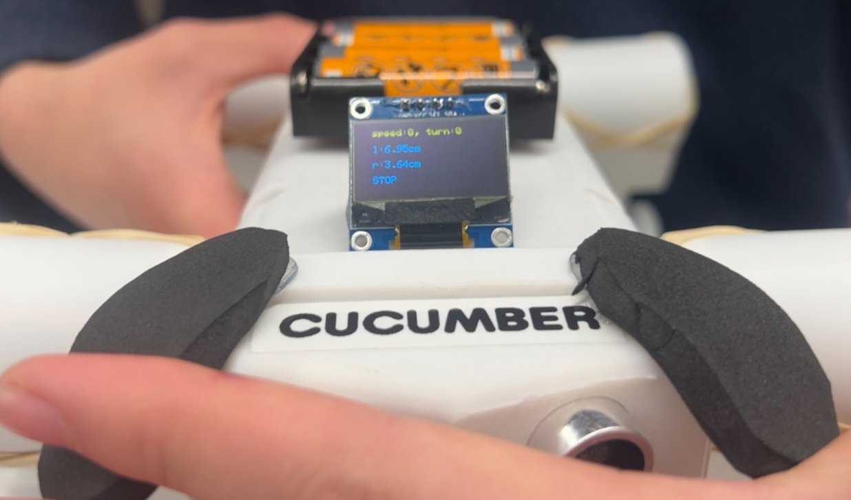
In Follow Mode, the display switches to a textual debug mode, where distance readings from the left and right ultrasonic sensors are printed in real-time. For example, the lines:
     print_word("l:18.2cm", 1);
     print_word("r:20.5cm", 2);
Result in the OLED showing the left and right sensor distances on lines 1 and 2 (using a 16-pixel
line height). The function print_word() uses a bitmap font to draw characters at
specific coordinates.
Font rendering is handled using ssd1306_draw_char() and ssd1306_draw_string(),
which in turn access a packed font table to decode characters into pixel patterns. Scaling is also
supported (though this project uses a scale of 1 for legibility).
The screen is initialized using:
ssd1306_init(&disp, 128, 64, 0x3C, i2c0);
The display's SDA and SCL pins are configured on i2c0 using 400 kHz fast-mode I2C
for fast data transfer. Pull-ups are enabled by:
     gpio_pull_up(OLED_SDA);
     gpio_pull_up(OLED_SCL);
The initialization routine sends a series of setup commands that configure the display mode, contrast, addressing scheme, scan direction, and charge pump control.
During runtime, the OLED serves two main purposes:
The transition between image and text display is seamless, as both operate through the same buffer and update mechanisms. The user sees an immediate response to mode toggles or proximity events.
To generate dog like noises, Direct Digital Synthesis (DDS) was utilized to generate precise audio waveforms with a phase accumulator to modulate frequency for the bark, growl, and howl sounds. 16-bit data packets are sent at a high sampling rate (50 kHz) to produce smooth analog signals for audio output. A timer interrupt routine handles sound generation in real time, updating the DAC output based on the current sound state and rampling aplitudes with attack and decay envelopes. Concurrency is achieved using protothreads and timer interrupts to ensure non-blocking operations and improved real-time performance.
Inital analysis analyzing the frequency spectrum of various dog noises like barking, howling, and growling. Some existing spectrogram data is available online, through pet sound classification reports. Additional analysis was also done by converting dog sound recordings into spectrograms using Sonic Visualizer. Much of the mathematical background for direct digital synthesis has been explained in the background math of the high-level design section. This Desmos link shows the mathematical approximation of the bark, growl, and howl sounds.
The interrupt handler, bark_irq() handles sound generation and contains three possible states defined by the SOUND_STATE variable, each corresponding to one sound. SOUND_STATE is modified using the web server by user input.
\[ \text{generated sound} = \begin{cases} \text{bark} & \text{if SOUND_STATE }= 0 \\ \text{growl} & \text{if SOUND_STATE }= 1 \\ \text{howl} & \text{if SOUND_STATE }= 2 \\ \text{nothing} & \text{otherwise} \\ \end{cases} \]
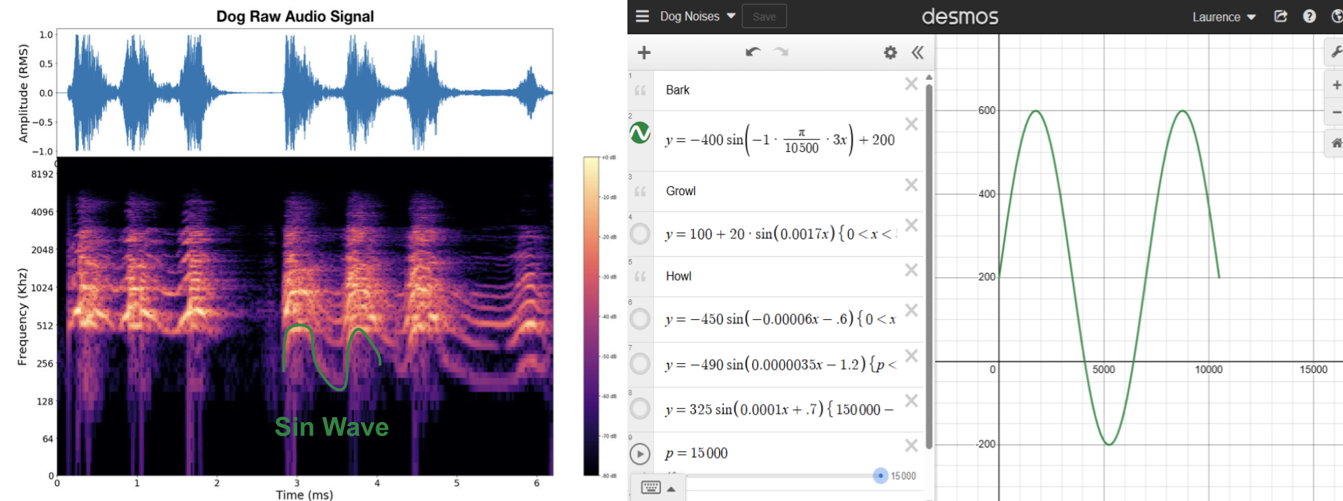
Using spectrogram data from the pet sound classification report, a bark sound can be modeled as a sin wave with two high peaks and one low peak. The spectrogram shows a higher pitched bark with an amplitude of around 300 Hz. In our implementation, we choose to center this sound at 200 Hz with a larger amplitude of 400 Hz after trial and error. We choose to use a bark duration of 10500, meaning the bark sound duration is 20 us * 10500 = 210 ms long. Overall, the frequency equation used is \[f(t)=-400\sin\left(-\frac{\pi}{10500}\cdot3t\right)+200\] The code implemenation uses this equation directly and then accumulates it using phase_accum_main_0. A code snippet of this implementation is included below. After accumulating this frequency, ramping is applied for smoother start and end audio signals. The sound only plays back once, therefore SOUND_STATE transitions to -1 after playback.
      if (SOUND_STATE == 0) {
        bark_frequency = -400*sin(-1*(BEEP_RADIAN*3*count_0))+200;
        phase_incr_main_0 = (bark_frequency * two32) / Fs ;
        phase_accum_main_0 += phase_incr_main_0  ;

        DAC_output_0 = fix2int15(multfix15(current_amplitude_0,
            sin_table[phase_accum_main_0>>24])) + 2048 ;

        if (count_0 < ATTACK_TIME) {
            current_amplitude_0 = (current_amplitude_0 + attack_inc) ;
        } else if (count_0 > BARK_DURATION - DECAY_TIME) {
            current_amplitude_0 = (current_amplitude_0 - decay_inc) ;
        }

        DAC_data_0 = (DAC_config_chan_B | (DAC_output_0 & 0xffff))  ;
        spi_write16_blocking(SPI_PORT, &DAC_data_0, 1) ;
        count_0 += 1 ;

        if (count_0 == BARK_DURATION) {
            current_amplitude_0 = 0;
            count_0 = 0 ;
            SOUND_STATE = -1 ;
        }
      }
A recording of the generated bark sound from the dog's speaker is also included below.
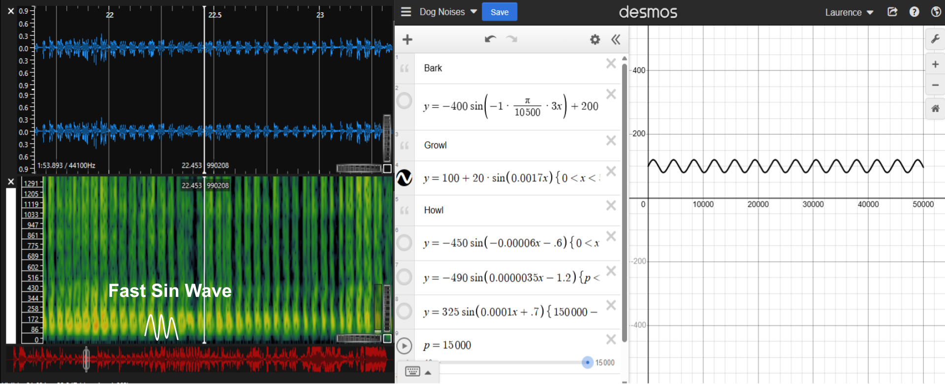
Using Sonic Visualizer on a recorded snippet of a dog growl, the spectogram of a dog growl can be viewed as a series of fast sine waves centered at around 100 Hz with a small amplitude. Each sine wave has a period of around 3696 samples or 73ms. The overall growl duration is 50000 samples or 1 second. Not shown in the graph is the addition of fake jitter in our code implementation for a more natural sounding growl noise. This is done by creating an array of 7 small integers (-10 to 10 range) and adding it to the final frequency by indexing this array. Mathematically, this can be represented as \[f(t)=100+20\cdot\sin\left(0.0017t\right)+\text{jitter}\] The code implementation is similar to the bark sound, with the only difference being the frequency equation. The snippet of this frequency code is shown below.
      int fake_jitter[] = {0, 3, -2, 1, -1, 4, -3};
      jitter = fake_jitter[count_0 % 7];
      growl_frequency = 100 + 20 * sin(0.0017 * count_0) + jitter;
A recording of the generated growl sound from the dog's speaker is also included below.
A recording of the general howl sound from the dog's speaker is also included below
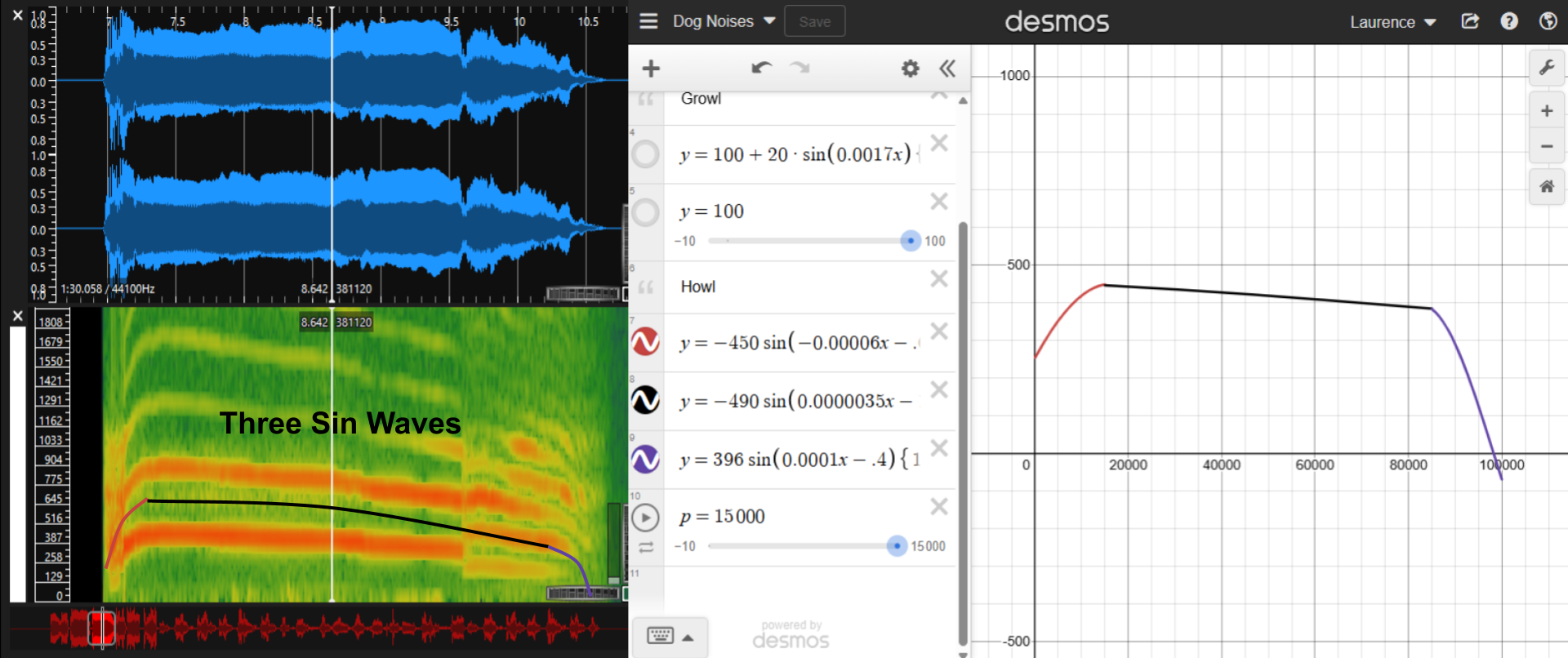
Using Sonic Visualizer again on a recorded snippet of a dog howl, the spectrogram of the dog howl can be viewed as three distinct regions: the first fast rise from 250 Hz to around 500Hz, the second prolonged howl time where frequency slowly decreases, and the third sharp decresae of the howl frequency to zero. The overall duration of the howl is 100000 samples or ~2 seconds, and the first and thrid sections last for 15000 samples or 300ms. Three sine waves were used to implement each section, however this is not necessary. A more optimized approach could have used parabolic apporximation instead. Mathematically, this frequency modulation can be viewed as \[ \text{f(t)} = \begin{cases} -450\sin\left(-0.00006x-.6\right) & \text{if } t \lt 15000 \\ -490\sin\left(0.0000035x-1.2\right) & \text{if } 15000 \leq t \lt 85000 \\ 396\sin\left(0.0001x-.4\right) & \text{if } 85000 \leq t \lt 10000\\ \end{cases} \] The code implementation is similar to the bark and growl sound, with the only difference being the frequency equation. The snippet of this frequency code is shown below.
    if (count_0 < 15000) {
        howl_frequency = -450*sin(-0.00006*count_0-0.6);
    } else if (count_0 < 85000) {
        howl_frequency = -490*sin(0.0000035*count_0-1.2);
    } else {
        howl_frequency = 396*sin(0.0001*count_0-.4);
    }
A recording of the generated howl sound from the dog's speaker is also included below.
Cucumber performed reliably across all functional areas during final testing. The robot was able to:
In Follow Mode, ultrasonic readings were accurate within ±1.5 cm at short ranges (under 80 cm), with control loop latency under 100 ms. Motor PWM and audio DAC interrupts ran concurrently without interfering with sensor polling or servo PWM control, demonstrating good concurrency and task separation using protothreads.
The full demonstration of these capabilities can be seen in our project demo video, embedded in the Demo section above.
The OLED screen remained stable for the most part under concurrent updates, with no flicker during text refreshes. Audio playback showed clear tonal patterns in all three barks, verified by spectrogram comparison using Sonic Visualizer in the software design section.
To ensure safety and robustness, all GPIO lines were tested during integration, and sensor timeouts were built into the code to prevent infinite blocking. We also added clamping for motor PWM duty cycles. The enclosure fully isolated the solderboard and motor wires to prevent shorts, and all mechanical parts passed continuous use tests.
The visual graphics from the OLED and the responsive sound/motion feedback made interactions intuitive and satisfying.
At startup, when first connect to the robot’s Wi-Fi, it could take awhile, but once connected, you can issue commands within seconds.
Cucumber successfully met our initial design goals: it is expressive, interactive, mobile, and able to respond to commands both manually and autonomously. The integration of motor control, sensing, display, sound generation, and a web interface resulted in a cohesive system that felt alive and engaging.
We faced several challenged throughout development that we were able to overcome including:
While we were able to implement all of our main goals, there are still many improvements that we could make in the future:
Our design adhered to relevant embedded systems best practices: safety through timeouts and voltage matching, concurrency via protothreads, and signal integrity through verified IC2/SPI scopes and interrupt-driven updates. We maintained modular code and hardware separation, making the robot easy to debug and modify.
The audio synthesis approach was based on our own DDS implementation, guided by Lab 1 of ECE 4760 Spring 25'. We reused and adapted code from:
All reused code was either public and properly licensed.
The group approves this report for inclusion on the course website.
The group approves the video for inclusion on the course youtube channel.
/**
* Copyright (c) Ananya Jajodia, Laurance Lai, Shao Stassen
*
* Motor Left Forward
* - GPIO 2 ---> en
* - GPIO 26 ---> inA
* - GPIO 22 ---> inB
*
* Motor Left Backward
* - GPIO 3 ---> en
* - GPIO 21 ---> inA
* - GPIO 20 ---> inB
*
* Motor Right Forward
* - GPIO 4 ---> en
* - GPIO 18 ---> inA
* - GPIO 19 ---> inB
*
* Motor Right Backward
* - GPIO 5 ---> en
* - GPIO 16 ---> inA
* - GPIO 17 ---> inB
*
* Servos
* - GPIO 6 ---> Left Forward Pin
* - GPIO 7 ---> Left Backward Pin
* - GPIO 8 ---> Right Forward Pin
* - GPIO 9 ---> Right Backward Pin
*
*
* Ultrasonic Sensors
* - GPIO 14 ---> Left Trigger
* - GPIO 15 ---> Left Echo
* - GPIO 27 ---> Right Trigger
* - GPIO 28 ---> Right Echo
*
* Digital to Analog Converter (DAC)
* - GPIO 10 ---> DAC SCK
* - GPIO 11 ---> DAC MOSI
* - GPIO 12 ---> DAC LDAC
* - GPIO 13 ---> DAC CS
*
* OLED Screen
* - GPIO 0 ---> SDA
* - GPIO 1 ---> SCL
*/
/***************************************************************************************
* Standard C / Pico SDK / third‑party headers *
***************************************************************************************/
#include // USB‑CDC printf / debug
#include // malloc/free, atoi, etc.
#include // sin(), fabsf(), M_PI
#include // strcpy, strcmp, strtok parsing
#include "pico/cyw43_arch.h" // Wi‑Fi driver + LED helper
#include "pico/stdlib.h" // GPIO helpers / delays
#include "pico/multicore.h" // Dual‑core support
#include "lwip/pbuf.h" // Packet buffers for raw TCP
#include "lwip/tcp.h" // Raw TCP API (no BSD sockets)
#include "dhcpserver.h" // Tiny DHCP responder (example)
#include "dnsserver.h" // Tiny DNS responder (wildcard)
#include "hardware/spi.h" // SPI peripheral – DAC + Wi‑Fi coexist
#include "hardware/sync.h" // save_and_disable_interrupts(), etc.
#include "hardware/irq.h" // IRQ vectors
#include "hardware/i2c.h" // I²C – SSD1306 OLED
#include "ssd1306.h" // Small OLED driver
#include "hardware/pwm.h" // PWM – motors & servos
#include "pt_cornell_rp2040_v1_3.h" // Protothread scheduler
/***************************************************************************************
* Alarm/Timer IRQ selection *
***************************************************************************************/
#define ALARM_NUM 0 // Use RP2040 hardware timer 0
#define ALARM_IRQ TIMER_IRQ_0 // Corresponding IRQ vector
/***************************************************************************************
* Fixed‑point (Q1.15) math helpers *
* These macros make the bark/growl DDS much faster than using floats in the ISR. *
***************************************************************************************/
typedef signed int fix15; // 16‑bit signed, 15 fractional bits
#define multfix15(a,b) ((fix15)((((signed long long)(a))*(signed long long)(b))>>15))
#define float2fix15(a) ((fix15)((a)*32768.0f)) // float → Q1.15
#define fix2float15(a) ((float)(a)/32768.0f) // Q1.15 → float (debug only)
#define int2fix15(a) ((fix15)((a) << 15)) // int → Q1.15
#define fix2int15(a) ((int)((a) >> 15)) // Q1.15 → int (truncate)
#define absfix15(a) abs(a) // sign‑safe abs()
#define divfix(a,b) ((fix15)(((signed long long)(a) << 15) / (b)))
/***************************************************************************************
* Direct‑Digital‑Synthesis (DDS) constants *
* Generates the audio waveforms for bark / growl / howl inside the timer ISR. *
***************************************************************************************/
#define two32 4294967296.0 // 2^32 – 32‑bit phase accumulator rollover
#define Fs 50000 // Sample rate 50 kHz (20 µs per tick)
#define DELAY 20 // 20 µs between ISR triggers
volatile unsigned int phase_accum_main_0; // 32‑bit phase accumulator
volatile unsigned int phase_incr_main_0 = (400.0*two32)/Fs; // Initial 400 Hz
#define sine_table_size 256
fix15 sin_table[sine_table_size]; // 8‑bit phase → Q1.15 sine lookup
/***************************************************************************************
* DAC output variables (double‑buffer style, though only channel B used) *
***************************************************************************************/
int DAC_output_0; // latest computed sample (12‑bit left‑justified)
int DAC_output_1; // (reserved – could be used for stereo)
/***************************************************************************************
* Envelope parameters for amplitude modulation of the bark/growl/howl *
***************************************************************************************/
fix15 max_amplitude = int2fix15(1); // 1.0 in Q1.15 → full‑scale
fix15 attack_inc; // ΔA per ISR during attack phase
fix15 decay_inc; // ΔA per ISR during decay phase
fix15 current_amplitude_0 = 0; // mutable envelope (core 0 ISR)
fix15 current_amplitude_1 = 0 ; // current amplitude (modified in ISR)
// Durations expressed in ISR ticks (20 µs each)
#define ATTACK_TIME 250 // 5 ms attack
#define DECAY_TIME 250 // 5 ms decay
#define SUSTAIN_TIME 10000 // 200 ms sustain
#define BEEP_REPEAT_INTERVAL 50000 // 1.0 s repeat interval
#define BARK_DURATION 10500 // ≈210 ms total bark envelope
#define GROWL_DURATION 50000 // 1.0 s growl
#define HOWL_DURATION 100000 // 2.0 s howl
/***************************************************************************************
* Jitter / frequency control variables *
***************************************************************************************/
int fake_jitter[] = {0,3,-2,1,-1,4,-3}; // small ±Hz offsets for "gravel" in growl
volatile unsigned int SOUND_STATE = 0; // 0=bark 1=growl 2=howl −1=idle
volatile unsigned int count_0 = 0; // sample counter inside ISR
int jitter = 0;
int bark_frequency = 0;
int growl_frequency = 0;
int howl_frequency = 0;
float BEEP_RADIAN = -M_PI/BARK_DURATION;
/***************************************************************************************
* DAC & SPI wiring *
***************************************************************************************/
uint16_t DAC_data_0; // 16‑bit SPI word to MCP4922 (channel B)
#define DAC_config_chan_B 0b1011000000000000 // ctl bits: gain=1x, active, channel B
#define PIN_CS 13 // ~CS to MCP4922
#define PIN_SCK 10 // SPI SCK
#define PIN_MOSI 11 // SPI MOSI
#define LDAC 12 // Pulled low to latch automatically
#define SPI_PORT spi1 // Use RP2040’s second SPI block
/***************************************************************************************
* Motor & Servo GPIO constants (see banner for mapping) *
***************************************************************************************/
// PWM timing – motors ≈1 kHz, servos 50 Hz
#define SERVO_WRAPVAL 20000
#define SERVO_CLKDIV 125.0f
#define MOTOR_WRAPVAL 5000
#define MOTOR_CLKDIV 25.0f
static uint32_t irq_mask = 0; // bitmask of PWM slices to service in ISR
/***************************************************************************************
* Data structures for motors and servos *
***************************************************************************************/
typedef struct { // DC motor mapped to a single PWM slice
volatile int en; // PWM pin (GPIO number)
int inA, inB; // H‑bridge logic (GPIO numbers)
volatile int speed;// requested duty (0‑5000)
volatile int old_speed;// cached last duty to avoid redundant writes
uint slice_num; // PWM slice index cached for speed
} motor_t;
typedef struct { // Hobby servo on its own PWM slice
int pin; // PWM pin (GPIO)
volatile int duty; // pulse width in timer counts (500‑2400)
volatile int old_duty;
uint slice_num; // PWM slice index
int inv; // 1 = mirror angle for right‑side legs
} servo_t;
/* Instantiate four motors with exact GPIO mapping */
/* Note: each .en pin is the PWM output; inA/inB drive H‑bridge direction */
/* Motor Left Forward — drives front‑left wheel when robot moves forward */
motor_t motor_left_forward = {2, 22, 26, 0, 0}; // en=GPIO2, inA=22, inB=26
/* Motor Left Backward — same gearbox, reverse rotation (separate H‑bridge) */
motor_t motor_left_backward = {3, 20, 21, 0, 0}; // en=GPIO3, inA=20, inB=21
/* Motor Right Forward — front‑right wheel forward */
motor_t motor_right_forward = {4, 19, 18, 0, 0}; // en=GPIO4, inA=19, inB=18
/* Motor Right Backward — front‑right wheel backward */
motor_t motor_right_backward= {5, 17, 16, 0, 0}; // en=GPIO5, inA=17, inB=16
/* —— Servos (leg joints) ———————————————————————————————————————————— */
/* Default duty = 1350 counts ≈ 1.35 ms pulse ≈ 90° neutral position */
/* inv flag mirrors angle so right‑side legs move symmetrically */
servo_t servo_left_forward = {6, 1350, 0, 0, 0}; // LF shoulder
servo_t servo_left_backward = {7, 1350, 0, 0, 0}; // LB hip
servo_t servo_right_forward = {8, 1350, 0, 0, 1}; // RF shoulder (inverted)
servo_t servo_right_backward = {9, 1350, 0, 0, 1}; // RB hip (inverted)
/* Convenience arrays for iteration */
motor_t* motors[] = {
&motor_left_forward, &motor_right_forward,
&motor_left_backward,&motor_right_backward
};
servo_t* servos[] = {
&servo_left_forward, &servo_right_forward,
&servo_left_backward,&servo_right_backward
};
/***************************************************************************************
* Pose angle lookup tables (degrees) *
* Used by set_all_servos() to animate dog poses from the web GUI. *
***************************************************************************************/
int angles[4] = { 90, 90, 90, 90}; // generic placeholder (not used)
int stand[4] = {120, 120, 120, 120}; // neutral standing
int sit[4] = {120, 120, 50, 50}; // sitting on hind legs
int paw[4] = {120, 30, 50, 50}; // raise left paw
int stretch[4] = { 30, 30, 180, 180}; // play bow / stretch
int lay[4] = { 45, 45, 45, 45}; // lie flat
int pee[4] = {145, 145, 120, 180}; // comical leg lift
int poo[4] = {140, 140, 85, 85}; // squat
int down_dog[4] = { 30, 30, 90, 90}; // downward‑dog yoga pose
int up_dog[4] = {110, 110, 180, 180}; // upward‑dog stretch
//*************************************************************** *
// ========================= I/O PIN MAP =========================
// ---------- Ultrasonic range sensors ----------
#define LEFT_TRIG_PIN 14 // GP14 drives the trigger pin of the LEFT HC-SR04
#define LEFT_ECHO_PIN 15 // GP15 reads the echo pulse width of the LEFT sensor
#define RIGHT_TRIG_PIN 27 // GP27 drives trigger on the RIGHT sensor
#define RIGHT_ECHO_PIN 28 // GP28 reads echo on the RIGHT sensor
// ---------- Global run-time state (shared across cores/threads) ----------
int access_led_state ; // copy of LED-0 state so the graphics thread can show AP activity
// int temp_sensor ; // enabling the RP2040 on-chip temperature sensor kills Wi-Fi
float left_distance ; // latest LEFT sensor range in cm (-1 = “out of range”)
float right_distance ; // latest RIGHT sensor range in cm (-1 = “out of range”)
int speed_field ; // −30 … +30 : forward/back speed command from UI/follow logic
int turn_field ; // −10 … +10 : steering command (positive = turn right)
int mode_field ; // 0 = manual, 1 = follow (parsed from URL)
int up_pressed ; // placeholders for future GPIO button interface
int left_pressed ;
int right_pressed ;
int down_pressed ;
char pose_name[32] = "None"; // textual pose selected in the web UI
int position_changed ; // non-zero → new pose arrived
int mode_changed ; // non-zero → manual ↔ follow toggled
int led_state = 0; // 0 = off, 1 = on (also echoed to UI)
bool follow_mode = false; // true → ultrasonic hand-follow is active
// ---------- I2C OLED (SSD1306) ----------
#define OLED_SDA 0 // GP0 → OLED SDA
#define OLED_SCL 1 // GP1 → OLED SCL
// ---------- Lightweight IP / HTTP-server parameters ----------
#define TCP_PORT 80 // port the web-server listens on
#define DEBUG_printf printf // easy way to silence debug output
#define POLL_TIME_S 5 // lwIP poll interval (seconds)
#define HTTP_GET "GET" // start token of an HTTP GET request
// HTTP response header template (status & length filled in at runtime)
#define HTTP_RESPONSE_HEADERS \
"HTTP/1.1 %d OK\n" /* status line */ \
"Content-Length: %d\n" /* byte-count of body */ \
"Content-Type: text/html; charset=utf-8\n" \
"Connection: close\n\n"
// Tiny test page (unused once the full slider page is served)
// commented out the HTML to avoid confusion with the C code and webpage
#define LED_TEST_BODY \
"<html>\n" \
"<body>\n" \
"<h1>Hello from Pico.</h1>\n" \
"<p>LED is %s</p>\n" \
"<p><a href=\"?led=%d\">Turn LED %s</a></p>\n" \
"</body>\n" \
"</html>\n"
// -------------------------------------------------------------------------
// Main HTML page (slider controls, pose buttons, mode toggle).
// This long macro is kept intact so your original formatting isn’t disturbed.
// -------------------------------------------------------------------------
// commented out the HTML to avoid confusion with the C code and webpage
#define LED_SLIDER_TEST_BODY \
"<!DOCTYPE html> \
<html><body><b>🐕 Page from PicoW -- ece4760 🐕</b>\
<p>Led is %s</br>\
CURRENTLY IN %s MODE %d<br>\
<form>\
<label for=\"led_control\">led(1/0):</label><br>\
<input type=\"text\" id=\"led_control\" name=\"led\" value=%d><br>\
<label for=\"speed\">speed:</label>\
<input type=\"range\" id=\"speed\" value=%d min=\"-10\" max=\"10\" name=\"speed\"\
oninput=\"this.nextElementSibling.value = this.value;\" onchange=\"submit()\">\
<output>%d</output>\
<p><label for=\"turn\">turn:</label>\
<input type=\"range\" id=\"turn\" value=%d min=\"-10\" max=\"10\" name=\"turn\"\
oninput=\"this.nextElementSibling.value = this.value;\" onchange=\"submit()\">\
<output>%d</output>\
</form> \
<p> Current pose = %s \
<p><a href=\"?pose=stay\">STAY</a>\
<p><a href=\"?pose=stand\">STAND</a>\
<p><a href=\"?pose=sit\">SIT</a>\
<p><a href=\"?pose=paw\">PAW</a>\
<p><a href=\"?pose=lay\">LAY DOWN</a>\
<p><a href=\"?pose=stretch\">STRETCH</a>\
<p><a href=\"?pose=pee\">PEE</a>\
<p><a href=\"?pose=poo\">POO</a>\
<p><a href=\"?pose=downdog\">DOWNWARD DOG</a>\
<p><a href=\"?pose=updog\">UPWARD DOG</a>\
<p><a href=\"?pose=bark\">BARK</a>\
<p><a href=\"?pose=growl\">GROWL</a>\
<p><a href=\"?pose=howl\">HOWL</a>\
<p><a href=\"?mode=%d\">SWITCH TO %s MODE</a>\
</body></html>"
// ---------- Hand-tune constants for follow-mode ----------
static int low_speed = 6; // slow reverse or creep forward
static int high_speed = 10; // full forward speed when following
static int mid_speed = 8; // (unused, kept for experimentation)
static int high_turn = 10; // tightest turn rate
static int low_turn = 4; // gentle steering
int follow_mode_curr = 0; // debounced copy for the UI
// Range thresholds (centimetres) for the HC-SR04 logic
static const float SENSOR_TOL = 15.0f; // diff to decide “left vs right”
static const float RANGE_TOO_CLOSE = 5.0f; // closer → back away
static const float RANGE_TOO_FAR = 25.0f; // farther → move forward
static const float RANGE_HIGH = 12.0f; // sweet spot to stop
// ---------- URL parameter keys used by the parser ----------
#define LED_PARAM "led=%d"
#define SPEED_FMT "speed=%d"
#define TURN_FMT "turn=%d"
#define POSE_FMT "pose=%s"
#define MODE_FMT "mode=%d"
// ---------- Misc convenience macros ----------
#define LED_TEST "/ledtest" // single-page endpoint
#define LED_GPIO 0 // CYW43 LED0 maps to STM32 GP0
#define HTTP_RESPONSE_REDIRECT \
"HTTP/1.1 302 Redirect\nLocation: http://%s" LED_TEST "\n\n"
// ---------- Other globals ----------
volatile int blink_delay_ms = 1000; // LED blinky period (ms)
ssd1306_t disp; // SSD1306 driver context
/* ------------------------------------------------------------------ */
/* OLED helper – draw a full-screen bitmap */
/* ------------------------------------------------------------------ */
static void oled_show_pose(const uint8_t *bmp) // bmp → pointer to 128×64 monochrome image
{
ssd1306_clear(&disp); // wipe entire display RAM
draw_bitmap_fullscreen(&disp, bmp); // copy user bitmap into display buffer
ssd1306_show(&disp); // push buffer over I²C to OLED panel
}
const uint8_t dog_poo_128x64[1024] = {......}; // 128×64 pixel image of a dog pooping
const uint8_t dog_paw_128x64[1024] = {......}; // 128×64 pixel image of a dog paw
const uint8_t dog_stand_128x64[1024] = {......}; // 128×64 pixel image of a dog standing
const uint8_t dog_sit_128x64[1024] = {......}; // 128×64 pixel image of a dog sitting
const uint8_t dog_stretch_128x64[1024] = {......}; // 128×64 pixel image of a dog stretching
const uint8_t dog_lay_128x64[1024] = {......}; // 128×64 pixel image of a dog lying down
const uint8_t dog_pee_128x64[1024] = {......}; // 128×64 pixel image of a dog peeing
const uint8_t dog_downdog_128x64[1024] = {......}; // 128×64 pixel image of a dog in downward dog
const uint8_t dog_updog_128x64[1024] = {......}; // 128×64 pixel image of a dog in upward dog
const uint8_t dog_bark_128x64[1024] = {......}; // 128×64 pixel image of a dog barking
const uint8_t dog_growl_128x64[1024] = {......}; // 128×64 pixel image of a dog growling
const uint8_t dog_howl_128x64[1024] = {......}; // 128×64 pixel image of a dog howling
/* Swap two 32-bit integers by pointer */
inline static void swap(int32_t *a, int32_t *b) {
int32_t *t = a; // keep original address of *a
*a = *b; // copy value of *b into *a
*b = *t; // copy saved value (old *a) into *b
}
/* ------------------------------------------------------------------ */
/* Pretty I2C writer that prints a diagnostic message on error */
inline static void fancy_write(i2c_inst_t *i2c,
uint8_t addr,
const uint8_t *src,
size_t len,
char *name)
{
/* Try to write a block. Result is number of bytes or negative err */
switch (i2c_write_blocking(i2c, addr, src, len, false)) {
case PICO_ERROR_GENERIC: // NACK by slave
printf("[%s] addr not acknowledged!\n", name);
break;
case PICO_ERROR_TIMEOUT: // bus stuck or no clock
printf("[%s] timeout!\n", name);
break;
default:
/* Success – we could print bytes-written but usually stay quiet */
// printf("[%s] wrote successfully %lu bytes!\n", name, len);
break;
}
}
/* Send a single command byte (val) to the SSD1306 */
inline static void ssd1306_write(ssd1306_t *p, uint8_t val) {
uint8_t d[2] = {0x00, val}; // 0x00 = command prefix
fancy_write(p->i2c_i, p->address, d, 2, "ssd1306_write");
}
/* ------------------------------------------------------------------ */
/* Allocate buffer and send the complete SSD1306 power-on command set */
bool ssd1306_init(ssd1306_t *p,
uint16_t width,
uint16_t height,
uint8_t address,
i2c_inst_t *i2c_instance)
{
/* Basic geometry parameters stored in struct */
p->width = width;
p->height = height;
p->pages = height / 8; // 8 vertical pixels per page
p->address = address;
p->i2c_i = i2c_instance;
/* Allocate frame-buffer (one byte per column per page) */
p->bufsize = p->pages * p->width;
if ((p->buffer = malloc(p->bufsize + 1)) == NULL) { // +1 for control byte
p->bufsize = 0;
return false; // allocation failed
}
++(p->buffer); // leave 1st byte for 0x40 data prefix
/* Below is the standard init sequence for 128×64/128×32 displays */
/* (adapted from makerportal’s repo) */
uint8_t cmds[] = {
SET_DISP, // display OFF
/* ---- timing/drive ---- */
SET_DISP_CLK_DIV, 0x80,
SET_MUX_RATIO, height - 1,
SET_DISP_OFFSET, 0x00,
/* ---- resolution/layout ---- */
SET_DISP_START_LINE,
/* ---- charge pump ---- */
SET_CHARGE_PUMP, p->external_vcc ? 0x10 : 0x14,
SET_SEG_REMAP | 0x01, // mirror columns
SET_COM_OUT_DIR | 0x08, // flip rows
SET_COM_PIN_CFG, width > 2 * height ? 0x02 : 0x12,
/* ---- contrast & power ---- */
SET_CONTRAST, 0xff,
SET_PRECHARGE, p->external_vcc ? 0x22 : 0xF1,
SET_VCOM_DESEL, 0x30,
SET_ENTIRE_ON, // follow RAM
SET_NORM_INV, // non-inverted
SET_DISP | 0x01, // display ON
/* ---- memory addressing ---- */
SET_MEM_ADDR, 0x00 // horizontal addressing
};
/* Send every command, one by one */
for (size_t i = 0; i < sizeof(cmds); ++i)
ssd1306_write(p, cmds[i]);
return true; // init OK
}
/* ------------------------------------------------------------------ */
/* Release buffer memory (caller turns display off beforehand) */
inline void ssd1306_deinit(ssd1306_t *p) {
free(p->buffer - 1); // adjust pointer because we bumped it in init
}
/* Quick helpers for power and modes -------------------------------- */
inline void ssd1306_poweroff (ssd1306_t *p){ ssd1306_write(p, SET_DISP | 0x00); }
inline void ssd1306_poweron (ssd1306_t *p){ ssd1306_write(p, SET_DISP | 0x01); }
inline void ssd1306_contrast (ssd1306_t *p, uint8_t val){ ssd1306_write(p, SET_CONTRAST); ssd1306_write(p, val); }
inline void ssd1306_invert (ssd1306_t *p, uint8_t inv){ ssd1306_write(p, SET_NORM_INV | (inv & 1)); }
/* Clear full framebuffer (set all bits to 0) */
inline void ssd1306_clear(ssd1306_t *p){ memset(p->buffer, 0, p->bufsize); }
/* ------------------------------------------------------------------ */
/* Low-level pixel access helpers */
void ssd1306_clear_pixel(ssd1306_t *p, uint32_t x, uint32_t y)
{
if (x >= p->width || y >= p->height) return; // bounds check
p->buffer[x + p->width * (y >> 3)] &= ~(0x1 << (y & 0x07)); // clear bit
}
void ssd1306_draw_pixel(ssd1306_t *p, uint32_t x, uint32_t y)
{
if (x >= p->width || y >= p->height) return;
p->buffer[x + p->width * (y >> 3)] |= 0x1 << (y & 0x07); // set bit
}
/* ------------------------------------------------------------------ */
/* Simple Bresenham-like line drawer (integer slope) */
void ssd1306_draw_line(ssd1306_t *p,
int32_t x1, int32_t y1,
int32_t x2, int32_t y2)
{
/* Ensure x1 <= x2 so we always draw left-to-right */
if (x1 > x2) { swap(&x1, &x2); swap(&y1, &y2); }
/* Vertical line optimisation */
if (x1 == x2) {
if (y1 > y2) swap(&y1, &y2);
for (int32_t i = y1; i <= y2; ++i) ssd1306_draw_pixel(p, x1, i);
return;
}
/* General case: y = m(x-x1)+y1 */
float m = (float)(y2 - y1) / (float)(x2 - x1);
for (int32_t i = x1; i <= x2; ++i) {
float y = m * (float)(i - x1) + (float)y1;
ssd1306_draw_pixel(p, i, (uint32_t)y);
}
}
/* ------------------------------------------------------------------ */
/* Rectangle helpers (filled, clear, outline) */
void ssd1306_clear_square(ssd1306_t *p,
uint32_t x, uint32_t y,
uint32_t width, uint32_t height)
{
for (uint32_t i = 0; i < width; ++i)
for (uint32_t j = 0; j < height; ++j)
ssd1306_clear_pixel(p, x + i, y + j);
}
void ssd1306_draw_square(ssd1306_t *p,
uint32_t x, uint32_t y,
uint32_t width, uint32_t height)
{
for (uint32_t i = 0; i < width; ++i)
for (uint32_t j = 0; j < height; ++j)
ssd1306_draw_pixel(p, x + i, y + j);
}
void ssd1306_draw_empty_square(ssd1306_t *p,
uint32_t x, uint32_t y,
uint32_t width, uint32_t height)
{
ssd1306_draw_line(p, x, y, x + width, y); // top
ssd1306_draw_line(p, x, y + height, x + width, y + height); // bottom
ssd1306_draw_line(p, x, y, x, y + height); // left
ssd1306_draw_line(p, x + width, y, x + width, y + height); // right
}
/* ------------------------------------------------------------------ */
/* 8×5 default font helpers */
void ssd1306_draw_char_with_font(ssd1306_t *p,
uint32_t x, uint32_t y,
uint32_t scale,
const uint8_t *font,
char c)
{
if (c < font[3] || c > font[4]) return; // not in charset
uint32_t parts_per_line = (font[0] >> 3) + ((font[0] & 7) > 0); // rows/8
/* Iterate over glyph columns */
for (uint8_t w = 0; w < font[1]; ++w) {
uint32_t pp = (c - font[3]) * font[1] * parts_per_line + w * parts_per_line + 5;
/* Each pp byte encodes 8 vertical pixels */
for (uint32_t lp = 0; lp < parts_per_line; ++lp) {
uint8_t line = font[pp];
for (int8_t j = 0; j < 8; ++j, line >>= 1)
if (line & 1) // pixel set?
ssd1306_draw_square(p,
x + w * scale,
y + ((lp << 3) + j) * scale,
scale, scale);
++pp;
}
}
}
/* Draw C-string using arbitrary font */
void ssd1306_draw_string_with_font(ssd1306_t *p,
uint32_t x, uint32_t y,
uint32_t scale,
const uint8_t *font,
const char *s)
{
for (int32_t x_n = x; *s; x_n += (font[1] + font[2]) * scale)
ssd1306_draw_char_with_font(p, x_n, y, scale, font, *(s++));
}
/* Convenience wrappers that hard-code the built-in 8×5 font */
void ssd1306_draw_char (ssd1306_t *p, uint32_t x, uint32_t y, uint32_t scale, char c)
{ ssd1306_draw_char_with_font(p, x, y, scale, font_8x5, c); }
void ssd1306_draw_string(ssd1306_t *p, uint32_t x, uint32_t y, uint32_t scale, const char *s)
{ ssd1306_draw_string_with_font(p, x, y, scale, font_8x5, s); }
/* ------------------------------------------------------------------ */
/* Helpers for reading little-endian integers from BMP */
static inline uint32_t ssd1306_bmp_get_val(const uint8_t *data,
const size_t offset,
uint8_t size)
{
switch (size) {
case 1: return data[offset];
case 2: return data[offset] | (data[offset + 1] << 8);
case 4: return data[offset] |
(data[offset + 1] << 8) |
(data[offset + 2] << 16) |
(data[offset + 3] << 24);
default: __builtin_unreachable(); // invalid size
}
}
/* ------------------------------------------------------------------ */
/* Monochrome BMP blitter with arbitrary X/Y offset */
void ssd1306_bmp_show_image_with_offset(ssd1306_t *p,
const uint8_t *data,
const long size,
uint32_t x_offset,
uint32_t y_offset)
{
if (size < 54) return; // header too small
/* Parse important BITMAPINFOHEADER fields */
const uint32_t bfOffBits = ssd1306_bmp_get_val(data, 10, 4);
const uint32_t biSize = ssd1306_bmp_get_val(data, 14, 4);
const uint32_t biWidth = ssd1306_bmp_get_val(data, 18, 4);
const int32_t biHeight = (int32_t)ssd1306_bmp_get_val(data, 22, 4);
const uint16_t biBitCount = (uint16_t)ssd1306_bmp_get_val(data, 28, 2);
const uint32_t biCompression = ssd1306_bmp_get_val(data, 30, 4);
if (biBitCount != 1) return; // not 1-bpp
if (biCompression != 0) return; // must be BI_RGB
/* Determine which palette entry is black (0) */
const int table_start = 14 + biSize;
uint8_t color_val = 0;
for (uint8_t i = 0; i < 2; ++i)
if (!((data[table_start + i * 4] << 16) |
(data[table_start + i * 4 + 1] << 8) |
data[table_start + i * 4 + 2])) { color_val = i; break; }
/* Row size (padded to 4-byte boundary) */
uint32_t bytes_per_line = (biWidth / 8) + (biWidth & 7 ? 1 : 0);
if (bytes_per_line & 3) bytes_per_line = (bytes_per_line ^ (bytes_per_line & 3)) + 4;
const uint8_t *img_data = data + bfOffBits; // pointer to pixel data
/* Direction: BMP rows are bottom-up if height positive */
int32_t step = biHeight > 0 ? -1 : 1;
int32_t border = biHeight > 0 ? -1 : -biHeight;
/* Iterate rows then columns */
for (uint32_t y = biHeight > 0 ? biHeight - 1 : 0; y != (uint32_t)border; y += step) {
for (uint32_t x = 0; x < biWidth; ++x) {
if (((img_data[x >> 3] >> (7 - (x & 7))) & 1) == color_val)
ssd1306_draw_pixel(p, x_offset + x, y_offset + y);
}
img_data += bytes_per_line;
}
}
/* Wrapper with zero offset */
inline void ssd1306_bmp_show_image(ssd1306_t *p,
const uint8_t *data,
const long size)
{
ssd1306_bmp_show_image_with_offset(p, data, size, 0, 0);
}
/* ------------------------------------------------------------------ */
/* Push framebuffer to OLED over I²C */
void ssd1306_show(ssd1306_t *p)
{
/* Set column & page address ranges */
uint8_t payload[] = {
SET_COL_ADDR, 0, p->width - 1,
SET_PAGE_ADDR, 0, p->pages - 1
};
if (p->width == 64) { // 64-px displays are mapped at +32
payload[1] += 32;
payload[2] += 32;
}
for (size_t i = 0; i < sizeof(payload); ++i)
ssd1306_write(p, payload[i]);
*(p->buffer - 1) = 0x40; // leading control byte = “data stream”
fancy_write(p->i2c_i, p->address, p->buffer - 1,
p->bufsize + 1, "ssd1306_show");
}
/* ------------------------------------------------------------------ */
/* Draw raw bitmap stored in program memory – centred or full-screen */
void draw_bitmap_centered(ssd1306_t *disp,
const uint8_t *bitmap,
int width, int height)
{
int x = (128 - width) / 2; // centre coords on 128×64 display
int y = (64 - height) / 2;
int byte_width = width / 8;
for (int j = 0; j < height; ++j)
for (int i = 0; i < width; ++i) {
int byte_index = j * byte_width + i / 8;
if (bitmap[byte_index] & (1 << (7 - (i % 8))))
ssd1306_draw_pixel(disp, x + i, y + j);
}
}
/* Draw 128×64 1-bpp bitmap to entire screen (bitmap is 1kB) */
void draw_bitmap_fullscreen(ssd1306_t *disp, const uint8_t *bitmap)
{
for (int page = 0; page < 8; ++page) // 8 pages × 8 rows
for (int col = 0; col < 128; ++col) { // 128 columns
uint8_t byte = bitmap[page * 128 + col];
for (int bit = 0; bit < 8; ++bit)
if ((byte >> bit) & 0x01) // test each pixel
ssd1306_draw_pixel(disp, col, page * 8 + bit);
}
}
/* ------------------------------------------------------------------ */
/* Lightweight structs for the raw-TCP web-server */
/* ------------------------------------------------------------------ */
typedef struct TCP_SERVER_T_ {
struct tcp_pcb *server_pcb; // listening socket (LWIP control block)
bool complete; // flag to signal main loop to stop
ip_addr_t gw; // gateway IP (192.168.4.1 in AP mode)
} TCP_SERVER_T;
typedef struct TCP_CONNECT_STATE_T_ {
struct tcp_pcb *pcb; // per-client connection control block
int sent_len; // how many bytes of header+body already sent
char headers[1024]; // HTTP response header scratch-pad
char result[2048]; // HTML body scratch-pad
int header_len; // cached strlen(headers)
int result_len; // cached strlen(result)
ip_addr_t *gw; // pointer back to server’s gateway IP
} TCP_CONNECT_STATE_T;
/* ------------------------------------------------------------------ */
/* Gracefully close a client connection and free its state */
/* ------------------------------------------------------------------ */
static err_t tcp_close_client_connection(TCP_CONNECT_STATE_T *con_state,
struct tcp_pcb *client_pcb,
err_t close_err)
{
if (client_pcb) { // only if PCB is still valid
assert(con_state && con_state->pcb == client_pcb); // sanity check
/* Detach all callbacks so LWIP won’t call into freed memory */
tcp_arg (client_pcb, NULL);
tcp_poll (client_pcb, NULL, 0);
tcp_sent (client_pcb, NULL);
tcp_recv (client_pcb, NULL);
tcp_err (client_pcb, NULL);
/* Attempt graceful FIN/ACK close */
err_t err = tcp_close(client_pcb);
if (err != ERR_OK) { // if stack can’t close cleanly…
DEBUG_printf("close failed %d, calling abort\n", err);
tcp_abort(client_pcb); // …abort the connection
close_err = ERR_ABRT;
}
/* Free the heap-allocated per-connection state */
if (con_state) free(con_state);
}
return close_err; // propagate final status to LWIP
}
/* ------------------------------------------------------------------ */
/* (Disabled) helper that would close the listening socket */
/* — not used because this program never exits. */
/* ------------------------------------------------------------------ */
// static void tcp_server_close(TCP_SERVER_T *state) {
// if (state->server_pcb) {
// tcp_arg(state->server_pcb, NULL);
// tcp_close(state->server_pcb);
// state->server_pcb = NULL;
// }
// }
/* ------------------------------------------------------------------ */
/* Callback when LWIP has successfully pushed data to the client */
/* ------------------------------------------------------------------ */
static err_t tcp_server_sent(void *arg, struct tcp_pcb *pcb, u16_t len)
{
TCP_CONNECT_STATE_T *con_state = (TCP_CONNECT_STATE_T*)arg;
DEBUG_printf("tcp_server_sent %u\n", len);
con_state->sent_len += len; // track cumulative bytes sent
/* If we’ve transmitted both header and HTML body, close the socket */
if (con_state->sent_len >= con_state->header_len + con_state->result_len) {
DEBUG_printf("all done\n");
return tcp_close_client_connection(con_state, pcb, ERR_OK);
}
return ERR_OK; // keep connection open for remaining bytes
}
// ========================================
// This routine actially parses the GET response to figure out what
// the browwer user asked for on the web page.
// This is another part I chnaged from the example
// to support more general parsing of several data items
static int test_server_content(const char *request, const char *params, char *result, size_t max_result_len) {
int len = 0;
// three data items sent in this example, but could be many more
static char param1[32], param2[16], param3[16], param4[16]; // param5[16]; param6[16], param7[16] ;
static char* token ;
// is it the corect page?
if (strncmp(request, LED_TEST, sizeof(LED_TEST) - 1) == 0) {
// // Get the curent state of the led
// // not used here, except as backup if web form fails
// bool value;
// cyw43_gpio_get(&cyw43_state, LED_GPIO, &value);
// int led_state = value;
// See what data the user asked for:
// the params string is trimmed by the receive funciton below to have
// only user-supplied data
// general data format is
// http://192.168.4.1/ledtest?name1=value1&name2=data2&name3=data3 and etc
// by the time the string gets here, the trimmed version is
// name1=value1&name2=data2&name3=data3
if (params) {
// parse the params using '&' delimeter
token = strtok((char*)params, "& ");
strcpy(param1, token) ;
token = strtok(NULL, "& ");
strcpy(param2, token) ;
token = strtok(NULL, "& ");
strcpy(param3, token) ;
// token = strtok(NULL, "& ");
// strcpy(param4, token) ;
// token = strtok(NULL, "& ");
// strcpy(param5, token) ;
// token = strtok(NULL, "& ");
// strcpy(param6, token) ;
// token = strtok(NULL, "& ");
// strcpy(param7, token) ;
// force to binary value and set LED state
cyw43_gpio_set(&cyw43_state, 0, led_state>0);
// set global to signal graphics thread
access_led_state = led_state>0 ;
// the second and third parameter begining is delimited by an '&'
// these tell the graphics thread what numbers to draw
if (!follow_mode){
sscanf(param2, SPEED_FMT, &speed_field);
sscanf(param3, TURN_FMT, &turn_field);
}
// now get the actual numbers
mode_changed = sscanf(param1, MODE_FMT, &mode_field);
if (mode_changed == 0 && !follow_mode){
position_changed = sscanf(param1, POSE_FMT, &pose_name);
if (position_changed == 0){
sscanf(param1, LED_PARAM, &led_state);
}
else {
if (strcmp(param1, "pose=stay") == 0){
speed_field = 0;
turn_field = 0;
}
else if (strcmp(param1, "pose=bark") == 0){
oled_show_pose(dog_bark_128x64);
SOUND_STATE = 0;
}
else if (strcmp(param1, "pose=growl") == 0){
oled_show_pose(dog_growl_128x64);
SOUND_STATE = 1;
}
else if (strcmp(param1, "pose=howl") == 0){
oled_show_pose(dog_howl_128x64);
SOUND_STATE = 2;
}
}
}
else {
if (mode_field){
follow_mode = true;
}
else {
follow_mode = false;
}
strcpy(pose_name, "stand");
speed_field = 0;
turn_field = 0;
set_all_servos(stand);
}
}
// Generate result web page using the above data
// by filling in the format fields in the http string
// speed_field occcurs twice: once for the slider position
// and once to update the numwerical value interactively.
len = snprintf(result, max_result_len, LED_SLIDER_TEST_BODY, led_state? "ON":"OFF",
follow_mode? "FOLLOW":"MANUAL", follow_mode, access_led_state, speed_field, speed_field, turn_field,
turn_field, pose_name, !follow_mode, follow_mode? "MANUAL":"FOLLOW");
}
return len;
}
/* ------------------------------------------------------------------ */
/* Callback: invoked when data arrives on a client connection */
/* ------------------------------------------------------------------ */
err_t tcp_server_recv(void *arg, struct tcp_pcb *pcb, struct pbuf *p, err_t err)
{
TCP_CONNECT_STATE_T *con_state = (TCP_CONNECT_STATE_T *)arg; // per-client context
/* ----- 1. connection closed by peer? -------------------------- */
if (!p) { // NULL pbuf ⇒ remote side closed
DEBUG_printf("connection closed\n");
return tcp_close_client_connection(con_state, pcb, ERR_OK);
}
assert(con_state && con_state->pcb == pcb); // sanity check
/* ----- 2. have payload → copy into header scratch-pad --------- */
if (p->tot_len > 0) {
DEBUG_printf("tcp_server_recv %d err %d\n", p->tot_len, err);
#if 0 // optional hexdump for debugging
for (struct pbuf *q = p; q; q = q->next)
DEBUG_printf("in: %.*s\n", q->len, q->payload);
#endif
/* Copy (and truncate if needed) into con_state->headers */
pbuf_copy_partial(p,
con_state->headers,
p->tot_len > sizeof(con_state->headers) - 1
? sizeof(con_state->headers) - 1
: p->tot_len,
0);
/* ----- 3. Only handle simple HTTP GET --------------------- */
if (strncmp(HTTP_GET, con_state->headers, sizeof(HTTP_GET) - 1) == 0) {
/* --- 3a. Split path and query-string ------------------ */
char *request = con_state->headers + sizeof(HTTP_GET); // skip \"GET \"
char *params = strchr(request, '?'); // start of \"?...\"
if (params) {
if (*params) { // non-empty query
char *space = strchr(request, ' '); // end of URL
*params++ = 0; // null-terminate path
if (space) *space = 0; // clip trailing \" HTTP/1.1\"
} else {
params = NULL; // lone '?' → ignore
}
}
/* --- 3b. Generate dynamic HTML into con_state->result - */
con_state->result_len =
test_server_content(request, params,
con_state->result,
sizeof(con_state->result));
DEBUG_printf("Request: %s?%s\n", request, params);
DEBUG_printf("Result: %d\n", con_state->result_len);
/* abort if body too big for our scratch buffer */
if (con_state->result_len > sizeof(con_state->result) - 1) {
DEBUG_printf("Too much result data %d\n",
con_state->result_len);
return tcp_close_client_connection(con_state, pcb, ERR_CLSD);
}
/* --- 3c. Build HTTP response headers ------------------ */
if (con_state->result_len > 0) { // normal 200 OK
con_state->header_len = snprintf(con_state->headers,
sizeof(con_state->headers),
HTTP_RESPONSE_HEADERS,
200,
con_state->result_len);
if (con_state->header_len > sizeof(con_state->headers) - 1) {
DEBUG_printf("Too much header data %d\n",
con_state->header_len);
return tcp_close_client_connection(con_state, pcb, ERR_CLSD);
}
} else { // 302 redirect
con_state->header_len = snprintf(con_state->headers,
sizeof(con_state->headers),
HTTP_RESPONSE_REDIRECT,
ipaddr_ntoa(con_state->gw));
DEBUG_printf("Sending redirect %s", con_state->headers);
}
/* --- 3d. Send headers --------------------------------- */
con_state->sent_len = 0;
err_t err = tcp_write(pcb,
con_state->headers,
con_state->header_len,
0); // copy into TCP buffer
if (err != ERR_OK) {
DEBUG_printf("failed to write header data %d\n", err);
return tcp_close_client_connection(con_state, pcb, err);
}
/* --- 3e. Send HTML body (if any) ---------------------- */
if (con_state->result_len) {
err = tcp_write(pcb,
con_state->result,
con_state->result_len,
0);
if (err != ERR_OK) {
DEBUG_printf("failed to write result data %d\n", err);
return tcp_close_client_connection(con_state, pcb, err);
}
}
}
tcp_recved(pcb, p->tot_len); // inform LWIP we’ve consumed bytes
}
pbuf_free(p); // free incoming pbuf chain
return ERR_OK; // keep connection alive
}
/* ------------------------------------------------------------------ */
/* Poll callback: fires if no traffic; we just drop idle clients */
/* ------------------------------------------------------------------ */
static err_t tcp_server_poll(void *arg, struct tcp_pcb *pcb)
{
TCP_CONNECT_STATE_T *con_state = (TCP_CONNECT_STATE_T *)arg;
DEBUG_printf("tcp_server_poll_fn\n");
return tcp_close_client_connection(con_state, pcb, ERR_OK); // timeout ⇒ close
}
/* ------------------------------------------------------------------ */
/* Error callback: invoked on LWIP fatal error except ERR_ABRT */
/* ------------------------------------------------------------------ */
static void tcp_server_err(void *arg, err_t err)
{
TCP_CONNECT_STATE_T *con_state = (TCP_CONNECT_STATE_T *)arg;
if (err != ERR_ABRT) { // ERR_ABRT already cleaned up
DEBUG_printf("tcp_client_err_fn %d\n", err);
tcp_close_client_connection(con_state, con_state->pcb, err);
}
}
/* ------------------------------------------------------------------ */
/* Accept callback: new client connection established */
/* ------------------------------------------------------------------ */
static err_t tcp_server_accept(void *arg,
struct tcp_pcb *client_pcb,
err_t err)
{
TCP_SERVER_T *state = (TCP_SERVER_T *)arg;
if (err != ERR_OK || !client_pcb) { // accept failed?
DEBUG_printf("failure in accept\n");
return ERR_VAL;
}
DEBUG_printf("client connected\n");
/* Allocate per-connection context on heap --------------------- */
TCP_CONNECT_STATE_T *con_state =
calloc(1, sizeof(TCP_CONNECT_STATE_T));
if (!con_state) {
DEBUG_printf("failed to allocate connect state\n");
return ERR_MEM;
}
con_state->pcb = client_pcb; // link back for asserts
con_state->gw = &state->gw; // for 302 redirect URL
/* Hook our callbacks into LWIP’s raw API ---------------------- */
tcp_arg (client_pcb, con_state);
tcp_sent (client_pcb, tcp_server_sent);
tcp_recv (client_pcb, tcp_server_recv);
tcp_poll (client_pcb, tcp_server_poll, POLL_TIME_S * 2);
tcp_err (client_pcb, tcp_server_err);
return ERR_OK; // tell LWIP we accepted the socket
}
/* ------------------------------------------------------------------ */
/* Initialise and start the raw-TCP web-server listener */
/* ------------------------------------------------------------------ */
static bool tcp_server_open(void *arg, const char *ap_name)
{
TCP_SERVER_T *state = (TCP_SERVER_T *)arg; // cast opaque ptr
DEBUG_printf("starting server on port %d\n", TCP_PORT);
/* 1. Create an LWIP “protocol control block” for a new socket */
struct tcp_pcb *pcb = tcp_new_ip_type(IPADDR_TYPE_ANY); // IPv4/IPv6 agnostic
if (!pcb) { // out of PCBs?
DEBUG_printf("failed to create pcb\n");
return false;
}
/* 2. Bind the PCB to port 80 on all interfaces in AP mode */
err_t err = tcp_bind(pcb, IP_ANY_TYPE, TCP_PORT);
if (err) {
DEBUG_printf("failed to bind to port %d\n", TCP_PORT);
return false;
}
/* 3. Convert to a listening socket with backlog = 1 */
state->server_pcb = tcp_listen_with_backlog(pcb, 1);
if (!state->server_pcb) { // listen failed
DEBUG_printf("failed to listen\n");
if (pcb) tcp_close(pcb); // clean up
return false;
}
/* 4. Attach per-server callback & context pointer */
tcp_arg (state->server_pcb, state); // gives cb ‘arg’
tcp_accept(state->server_pcb, tcp_server_accept); // on new client
printf("Try connecting to '%s' (press 'd' to disable access point)\n",
ap_name);
return true; // listener ready
}
/* ------------------------------------------------------------------ */
/* Non-blocking console hot-key handler */
/* (In this trimmed build we just detect ‘d/D’; full version */
/* would schedule a worker to shut down the Wi-Fi AP.) */
/* ------------------------------------------------------------------ */
// Original, more elaborate version left commented out above for reference.
void key_pressed_func(void *param)
{
assert(param); // must have context
int key = getchar_timeout_us(0); // poll UART RX
if (key == 'd' || key == 'D') { // user pressed ‘d’
// In IRQ context, we’d post a job to the main loop here:
// async_context_set_work_pending(((TCP_SERVER_T*)param)->context,
// &key_pressed_worker);
}
}
/* ------------------------------------------------------------------ */
/* bark_irq — Timer-0 ISR fires every 20 µs (Fs = 50 kHz) */
/* Generates bark / growl / howl via direct-digital synthesis */
/* ------------------------------------------------------------------ */
static void bark_irq(void)
{
/* ---- Clear IRQ flag and schedule next interrupt -------------- */
hw_clear_bits(&timer_hw->intr, 1u << ALARM_NUM); // ack alarm-0
timer_hw->alarm[ALARM_NUM] = timer_hw->timerawl + DELAY; // +20 µs
/* ---- State 0 : “Bark” envelope / frequency sweep ------------- */
if (SOUND_STATE == 0) {
/* parabolic-ish sweep gives dog-bark flavour */
bark_frequency = -400 * sin(BEEP_RADIAN * 3 * count_0) + 200;
/* DDS phase advance */
phase_incr_main_0 = (bark_frequency * two32) / Fs;
phase_accum_main_0 += phase_incr_main_0;
/* Sine lookup → scale by current amplitude → add 2048 offset */
DAC_output_0 = fix2int15(
multfix15(current_amplitude_0,
sin_table[phase_accum_main_0 >> 24])) + 2048;
/* Attack / decay envelope */
if (count_0 < ATTACK_TIME) current_amplitude_0 += attack_inc;
else if (count_0 > BARK_DURATION-DECAY_TIME) current_amplitude_0 -= decay_inc;
/* Ship 12-bit sample to MCP4922 (channel-B) */
DAC_data_0 = DAC_config_chan_B | (DAC_output_0 & 0x0FFF);
spi_write16_blocking(SPI_PORT, &DAC_data_0, 1);
/* Advance sample counter, stop when envelope finished */
if (++count_0 == BARK_DURATION) {
current_amplitude_0 = 0; count_0 = 0; SOUND_STATE = -1;
}
}
/* ---- State 1 : “Growl” (low, jittery) ------------------------ */
else if (SOUND_STATE == 1) {
jitter = fake_jitter[count_0 % 7]; // pseudo-random ±Hz
growl_frequency = 100 + 20 * sin(0.0017 * count_0) + jitter;
phase_incr_main_0 = (growl_frequency * two32) / Fs;
phase_accum_main_0 += phase_incr_main_0;
DAC_output_0 = fix2int15(
multfix15(current_amplitude_0,
sin_table[phase_accum_main_0 >> 24])) + 2048;
if (count_0 < ATTACK_TIME) current_amplitude_0 += attack_inc;
else if (count_0 > GROWL_DURATION-DECAY_TIME) current_amplitude_0 -= decay_inc;
DAC_data_0 = DAC_config_chan_B | (DAC_output_0 & 0x0FFF);
spi_write16_blocking(SPI_PORT, &DAC_data_0, 1);
if (++count_0 == GROWL_DURATION) { current_amplitude_0 = 0; count_0 = 0; SOUND_STATE = -1; }
}
/* ---- State 2 : “Howl” (rising then falling pitch) ------------ */
else if (SOUND_STATE == 2) {
/* Piecewise pitch contour */
if (count_0 < 15000) howl_frequency = -450 * sin(-0.00006 * count_0 - 0.6);
else if (count_0 < 85000) howl_frequency = -490 * sin(0.0000035 * count_0 - 1.2);
else howl_frequency = 396 * sin(0.0001 * count_0 - 0.4);
phase_incr_main_0 = (howl_frequency * two32) / Fs;
phase_accum_main_0 += phase_incr_main_0;
DAC_output_0 = fix2int15(
multfix15(current_amplitude_0,
sin_table[phase_accum_main_0 >> 24])) + 2048;
if (count_0 < ATTACK_TIME) current_amplitude_0 += attack_inc;
else if (count_0 > HOWL_DURATION-DECAY_TIME) current_amplitude_0 -= decay_inc;
DAC_data_0 = DAC_config_chan_B | (DAC_output_0 & 0x0FFF);
spi_write16_blocking(SPI_PORT, &DAC_data_0, 1);
if (++count_0 == HOWL_DURATION) { current_amplitude_0 = 0; count_0 = 0; SOUND_STATE = -1; }
}
}
/* ------------------------------------------------------------------ */
/* Busy-wait delay in microseconds (uses high-res RTC) */
/* ------------------------------------------------------------------ */
void sleep_us_busy_wait(uint64_t us)
{
absolute_time_t t = make_timeout_time_us(us); // target timestamp
sleep_until(t); // blocks until reached
}
/* ------------------------------------------------------------------ */
/* Ultrasonic ping distance helper */
/* Returns distance in cm or −1.0 on timeout/error */
/* ------------------------------------------------------------------ */
float get_distance_cm(int trig_pin, int echo_pin)
{
/* 1. 10 µs trigger pulse */
gpio_put(trig_pin, 0); busy_wait_us(2);
gpio_put(trig_pin, 1); busy_wait_us(10);
gpio_put(trig_pin, 0);
/* 2. Critical-section: ignore other IRQs while timing echo */
uint32_t irq_state = save_and_disable_interrupts();
/* 2a. Wait for rising edge, abort after 25 ms (no echo) */
absolute_time_t t0 = get_absolute_time();
while (!gpio_get(echo_pin)) {
if (absolute_time_diff_us(t0, get_absolute_time()) > 25000) {
restore_interrupts(irq_state);
return -1.0f; // out of range
}
}
/* 2b. Measure pulse width */
absolute_time_t echo_start = get_absolute_time();
while (gpio_get(echo_pin)) {
if (absolute_time_diff_us(echo_start, get_absolute_time()) > 25000) {
restore_interrupts(irq_state);
return -1.0f; // stuck high ⇒ error
}
}
absolute_time_t echo_end = get_absolute_time();
restore_interrupts(irq_state); // exit critical-section
/* 3. Convert microseconds to centimetres (speed of sound) */
int64_t pulse_us = absolute_time_diff_us(echo_start, echo_end);
return pulse_us / 58.0f; // 58 µs ≈ 1 cm round-trip
}
/* ======================= OLED SUPPORT ======================= */
/* Configure I²C pins GP0/GP1 for 400 kHz fast-mode */
void setup_oled_gpios(void)
{
i2c_init(i2c0, 400000);
gpio_set_function(OLED_SDA, GPIO_FUNC_I2C);
gpio_set_function(OLED_SCL, GPIO_FUNC_I2C);
gpio_pull_up(OLED_SDA); // required for open-drain
gpio_pull_up(OLED_SCL);
}
/* Initialise SSD1306 driver context (128×64 at I²C address 0x3C) */
void setup_oled(void)
{
disp.external_vcc = false; // on-board charge-pump
ssd1306_init(&disp, 128, 64, 0x3C, i2c0);
}
/* Draw a single word (8-pixel font) at ‘line’ (0-based, 16-px high) */
void print_word(char *word, int line)
{
line *= 16; // convert to pixel Y
ssd1306_draw_string(&disp, 8, line, 1, word);
ssd1306_show(&disp); // refresh display
}
/* ======================= HELPERS =========================== */
/* Generic integer map: linear remap from one range to another */
int map(int x, int in_min, int in_max, int out_min, int out_max)
{
return (x - in_min) * (out_max - out_min) /
(in_max - in_min) + out_min;
}
/* ============================================================= */
/* PWM wrap IRQ – fires whenever any motor/servo slice hits wrap */
/* Services up-to-date duty cycles for four motors + four servos */
/* ============================================================= */
void on_pwm_wrap()
{
uint32_t status = pwm_get_irq_status_mask(); // bit-mask: which slices asserted IRQ
for (int i = 0; i < 4; i++) { // we have 4 motors and 4 servos
/* -------------------- MOTOR SECTION -------------------- */
motor_t *m = motors[i];
if (status & (1u << m->slice_num)) { // did this slice trigger?
pwm_clear_irq(m->slice_num); // acknowledge slice
if (m->speed != m->old_speed) { // speed command changed?
m->old_speed = m->speed; // remember new value
/* update duty cycle (chan = A or B chosen by GPIO) */
pwm_set_chan_level(m->slice_num,
pwm_gpio_to_channel(m->en),
m->speed);
}
}
/* -------------------- SERVO SECTION -------------------- */
servo_t *s = servos[i];
if (status & (1u << s->slice_num)) { // same idea for servo slices
pwm_clear_irq(s->slice_num);
if (s->duty != s->old_duty) { // pulse-width changed?
s->old_duty = s->duty;
pwm_set_chan_level(s->slice_num,
pwm_gpio_to_channel(s->pin),
s->duty);
}
}
}
}
/* ============================================================= */
/* Motor helper functions – direction pins + PWM duty control */
/* ============================================================= */
void motor_init(motor_t *motor)
{
/* --- configure direction pins (inA/inB) -------------------- */
gpio_init(motor->inA); gpio_set_dir(motor->inA, 1); gpio_put(motor->inA, 1);
gpio_init(motor->inB); gpio_set_dir(motor->inB, 1); gpio_put(motor->inB, 0);
/* --- configure enable pin as PWM output -------------------- */
gpio_set_function(motor->en, GPIO_FUNC_PWM);
motor->slice_num = pwm_gpio_to_slice_num(motor->en);
/* --- slice setup: 5 kHz center-aligned PWM ----------------- */
pwm_clear_irq(motor->slice_num);
pwm_set_wrap (motor->slice_num, MOTOR_WRAPVAL); // period
pwm_set_clkdiv(motor->slice_num, MOTOR_CLKDIV); // clock divide
pwm_set_chan_level(motor->slice_num,
pwm_gpio_to_channel(motor->en), 0); // start stopped
pwm_set_enabled(motor->slice_num, true);
irq_mask |= (1u << motor->slice_num); // enable ISR for this slice
}
void motor_forward(motor_t *motor, int speed)
{
gpio_put(motor->inA, 1); // A = 1, B = 0 → forward
gpio_put(motor->inB, 0);
motor->speed = map(speed, 0, 30, 3000, 5000); // map 0‒30 to PWM counts
}
void motor_backward(motor_t *motor, int speed)
{
gpio_put(motor->inA, 0); // A = 0, B = 1 → reverse
gpio_put(motor->inB, 1);
motor->speed = map(speed, 0, 30, 3000, 5000);
}
void motor_stop(motor_t *motor)
{
gpio_put(motor->inA, 0); gpio_put(motor->inB, 0); // coast
motor->speed = 0;
}
/* Drive all four wheels given global speed (−10…10) and turn (−10…10) */
void move_all_motors(int speed, int turn)
{
/* compute individual wheel speeds: simple differential steering */
int left_speed = speed + turn * 2; // turn>0 → speed up left, slow right
int right_speed = speed - turn * 2;
printf("Left Speed: %d, Right Speed: %d\n", left_speed, right_speed);
/* clamp to ±30 (maps to full PWM) */
left_speed = left_speed < -30 ? -30 : (left_speed > 30 ? 30 : left_speed);
right_speed = right_speed < -30 ? -30 : (right_speed > 30 ? 30 : right_speed);
/* Left wheels ------------------------------------------------ */
if (left_speed < 0) { motor_backward(&motor_left_forward, -left_speed);
motor_backward(&motor_left_backward,-left_speed); }
else if (left_speed > 0) { motor_forward (&motor_left_forward, left_speed);
motor_forward (&motor_left_backward, left_speed); }
else { motor_stop (&motor_left_forward);
motor_stop (&motor_left_backward); }
/* Right wheels ----------------------------------------------- */
if (right_speed < 0) { motor_backward(&motor_right_forward, -right_speed);
motor_backward(&motor_right_backward,-right_speed); }
else if (right_speed > 0) { motor_forward (&motor_right_forward, right_speed);
motor_forward (&motor_right_backward, right_speed); }
else { motor_stop (&motor_right_forward);
motor_stop (&motor_right_backward); }
}
/* ============================================================= */
/* Servo helper functions – 50 Hz PWM, 500-2400 µs pulse widths */
/* ============================================================= */
void servo_init(servo_t *servo)
{
gpio_set_function(servo->pin, GPIO_FUNC_PWM);
servo->slice_num = pwm_gpio_to_slice_num(servo->pin);
pwm_clear_irq(servo->slice_num);
pwm_set_wrap (servo->slice_num, SERVO_WRAPVAL); // 20 ms period
pwm_set_clkdiv(servo->slice_num, SERVO_CLKDIV); // 1 µs resolution
pwm_set_chan_level(servo->slice_num,
pwm_gpio_to_channel(servo->pin), 0);
pwm_set_enabled(servo->slice_num, true);
irq_mask |= (1u << servo->slice_num); // serviced by on_pwm_wrap()
}
/* Set servo to absolute angle (0-180°). ‘inv’ flips direction if needed */
void servo_angle(servo_t *servo, int angle)
{
if (servo->inv) angle = 180 - angle; // mirror for opposite side
servo->duty = map(angle, 0, 180, 500, 2400); // µs pulse → PWM counts
}
/* Smoothly sweep one servo to target angle (blocking) */
void servo_sweep_to(servo_t *servo, int target_angle)
{
int current_angle = map(servo->duty, 500, 2400, 0, 180);
if (servo->inv) current_angle = 180 - current_angle;
while (current_angle != target_angle) {
current_angle += (current_angle < target_angle) ? 1 : -1;
servo_angle(servo, current_angle);
sleep_ms(5); // ~180 deg in ~1 s
}
}
/* Simultaneously move all 4 servos to target_angles[] (blocking) */
void set_all_servos(int target_angles[4])
{
int current_angles[4];
bool done = false;
/* capture current positions */
for (int i = 0; i < 4; i++) {
int a = map(servos[i]->duty, 500, 2400, 0, 180);
current_angles[i] = servos[i]->inv ? 180 - a : a;
}
/* step each servo 1° per loop until all reach targets */
while (!done) {
done = true;
for (int i = 0; i < 4; i++) {
if (current_angles[i] < target_angles[i]) { current_angles[i]++; done = false; }
else if (current_angles[i] > target_angles[i]) { current_angles[i]--; done = false; }
servo_angle(servos[i], current_angles[i]);
}
sleep_ms(10);
}
}
/* ============================================================= */
/* Hand-follow decision logic – maps ultrasonic ranges to motion */
/* ============================================================= */
static void hand_follow_decide(float left_cm, float right_cm)
{
speed_field = 0; // default stop
bool have_left = (left_cm > 0); // valid readings?
bool have_right = (right_cm > 0);
/* Pick nearest or averaged distance for central hand ---------- */
float nearest = -1.0f;
if (have_left && have_right && fabsf(left_cm - right_cm) < SENSOR_TOL)
nearest = 0.5f * (left_cm + right_cm);
else if (have_left && have_right)
nearest = (left_cm < right_cm) ? left_cm : right_cm;
else if (have_left) nearest = left_cm;
else if (have_right) nearest = right_cm;
float diff = left_cm - right_cm; // +ve ⇒ hand left side
if (left_cm <= RANGE_TOO_CLOSE && right_cm <= RANGE_TOO_CLOSE) {
/* Hand too close → back up straight, trigger bark */
speed_field = -high_speed; turn_field = 0; SOUND_STATE = 0;
print_word("CLOSE", 3);
}
else if (!have_left) { /* hand only on right side */
speed_field = 0; turn_field = +high_turn;
}
else if (!have_right) { /* hand only on left side */
speed_field = 0; turn_field = -high_turn;
}
else if (diff > SENSOR_TOL) { /* hand nearer left sensor */
speed_field = +high_speed; turn_field = +high_turn;
}
else if (diff < -SENSOR_TOL) { /* hand nearer right sensor */
speed_field = +high_speed; turn_field = -high_turn;
}
else if (nearest == -1.0f || nearest > RANGE_TOO_FAR) { /* lost */
speed_field = +high_speed; turn_field = 0;
print_word("FAR", 3);
}
else if (nearest <= RANGE_HIGH) { /* sweet spot → stop */
speed_field = 0; turn_field = 0;
print_word("STOP", 3);
}
/* Debug readout on OLED line-0 */
char word_buffer[50];
sprintf(word_buffer, "speed:%d, turn:%d", speed_field, turn_field);
print_word(word_buffer, 0);
}
// ========================== Threads =========================
// ------------ Motor/pose state-machine protothread (core-1) ------------
static PT_THREAD(protothread_motors(struct pt *pt)) // protoThread definition
{
PT_BEGIN(pt); // required macro to start PT
set_all_servos(angles); // Initialise legs to neutral 90-degree pose once
while (1) { // ----- main PT loop -----
move_all_motors(speed_field, turn_field); // drive wheels every pass
if (!follow_mode) { // ---- MANUAL / POSE ----
/* Choose bitmap + servo set by string in pose_name */
if (strcmp(pose_name, "stand") == 0) { oled_show_pose(dog_stand_128x64); set_all_servos(stand); }
else if (strcmp(pose_name, "sit") == 0) { oled_show_pose(dog_sit_128x64); set_all_servos(sit); }
else if (strcmp(pose_name, "paw") == 0) { oled_show_pose(dog_paw_128x64); set_all_servos(sit); set_all_servos(paw); }
else if (strcmp(pose_name, "stretch") == 0) { oled_show_pose(dog_stretch_128x64); set_all_servos(stretch); }
else if (strcmp(pose_name, "lay") == 0) { oled_show_pose(dog_lay_128x64); set_all_servos(lay); }
else if (strcmp(pose_name, "pee") == 0) { oled_show_pose(dog_pee_128x64); set_all_servos(pee); }
else if (strcmp(pose_name, "poo") == 0) { oled_show_pose(dog_poo_128x64); set_all_servos(poo); }
else if (strcmp(pose_name, "downdog") == 0) { oled_show_pose(dog_downdog_128x64); set_all_servos(down_dog);}
else if (strcmp(pose_name, "updog") == 0) { oled_show_pose(dog_updog_128x64); set_all_servos(up_dog); }
}
else { // ------------- FOLLOW MODE -------------
/* 1. Read both ultrasonic sensors */
left_distance = get_distance_cm(LEFT_TRIG_PIN, LEFT_ECHO_PIN);
right_distance = get_distance_cm(RIGHT_TRIG_PIN, RIGHT_ECHO_PIN);
/* 2. Decide speed/turn based on hand position */
hand_follow_decide(left_distance, right_distance);
/* 3. OLED diagnostic output (two lines) */
char word_buffer1[50], word_buffer2[50];
sprintf(word_buffer2, "l:%.2fcm", left_distance);
sprintf(word_buffer1, "r:%.2fcm", right_distance);
print_word(word_buffer1, 2); // right sensor on line-2
print_word(word_buffer2, 1); // left sensor on line-1
ssd1306_clear(&disp); // clear for next refresh
sleep_ms(500); // ~2 Hz update rate
}
}
PT_END(pt); // required macro to end PT
}
/* ---------------- Simple LED heartbeat protothread ---------------- */
static PT_THREAD(protothread_blinky(struct pt *pt))
{
PT_BEGIN(pt);
while (true) {
int s = speed_field; // use robot speed as blink period
if (speed_field < 0) s = -s; // negate if backing up
cyw43_gpio_set(&cyw43_state, LED_GPIO, true); // LED on
sleep_ms(s); // delay
cyw43_gpio_set(&cyw43_state, LED_GPIO, false); // LED off
sleep_ms(s); // delay
}
PT_END(pt);
}
// ========================== Threads =========================
/* ---------------- Core-1 entry point ----------------------- */
void core1_entry()
{
/* Optionally add blinky PT, but only motors is needed */
// pt_add_thread(protothread_blinky);
pt_add_thread(protothread_motors); // register motor thread
pt_schedule_start; // start the protothread scheduler
}
/* ========================== Main =========================== */
int main()
{
stdio_init_all(); // enable USB-serial stdio
/* ---- OLED ---- */
setup_oled_gpios(); // configure I²C pins
setup_oled(); // init SSD1306 driver
oled_show_pose(dog_stand_128x64); // show default bitmap
/* ---- Motors + Servos ---- */
motor_init(&motor_left_forward); // initialise each H-bridge
motor_init(&motor_left_backward);
motor_init(&motor_right_forward);
motor_init(&motor_right_backward);
servo_init(&servo_left_forward); // initialise PWM for each servo
servo_init(&servo_left_backward);
servo_init(&servo_right_forward);
servo_init(&servo_right_backward);
/* ---- Enable combined PWM IRQ handler (motors+servos) ---- */
pwm_set_irq_mask_enabled(irq_mask, true); // enable IRQ on our slices
irq_set_exclusive_handler(PWM_IRQ_WRAP, on_pwm_wrap);
irq_set_enabled(PWM_IRQ_WRAP, true);
/* ---- DAC (MCP4922) for sound ---- */
spi_init(SPI_PORT, 20000000); // 20 MHz SPI
spi_set_format(SPI_PORT, 16, 0, 0, 0); // 16-bit, mode-0
gpio_set_function(PIN_SCK, GPIO_FUNC_SPI);
gpio_set_function(PIN_MOSI, GPIO_FUNC_SPI);
gpio_set_function(PIN_CS, GPIO_FUNC_SPI);
gpio_init(LDAC); gpio_set_dir(LDAC, GPIO_OUT); gpio_put(LDAC, 0);
/* pre-compute amplitude ramp increments */
attack_inc = divfix(max_amplitude, int2fix15(ATTACK_TIME));
decay_inc = divfix(max_amplitude, int2fix15(DECAY_TIME));
/* fill 256-entry sine lookup table (0-2047) */
for (int ii = 0; ii < sine_table_size; ii++)
sin_table[ii] = float2fix15(2047 * sinf((float)ii * 2 * M_PI / sine_table_size));
/* ---- Periodic timer for bark/growl/howl ISR ---- */
hw_set_bits(&timer_hw->inte, 1u << ALARM_NUM); // enable alarm-0 IRQ
irq_set_exclusive_handler(ALARM_IRQ, bark_irq);
irq_set_enabled(ALARM_IRQ, true);
timer_hw->alarm[ALARM_NUM] = timer_hw->timerawl + DELAY; // first fire in 20 µs
/* ---- Ultrasonic pins ---- */
gpio_init(LEFT_TRIG_PIN); gpio_set_dir(LEFT_TRIG_PIN, GPIO_OUT); gpio_put(LEFT_TRIG_PIN, 0);
gpio_init(LEFT_ECHO_PIN); gpio_set_dir(LEFT_ECHO_PIN, GPIO_IN);
gpio_init(RIGHT_TRIG_PIN); gpio_set_dir(RIGHT_TRIG_PIN, GPIO_OUT); gpio_put(RIGHT_TRIG_PIN, 0);
gpio_init(RIGHT_ECHO_PIN); gpio_set_dir(RIGHT_ECHO_PIN, GPIO_IN);
sleep_ms(100); // allow sensors to settle
/* ---- Bring-up Wi-Fi access-point + web server ---- */
TCP_SERVER_T *state = calloc(1, sizeof(TCP_SERVER_T)); // hold server context
if (!state) { DEBUG_printf("failed to allocate state\n"); return 1; }
if (cyw43_arch_init()) { // init CYW43439 + LWIP
DEBUG_printf("failed to initialise Wi-Fi\n"); return 1;
}
stdio_set_chars_available_callback(key_pressed_func, state); // hot-key handler
const char *ap_name = "picow_dog"; // SSID
#if 1
const char *password = "password"; // WPA2 passphrase
#else
const char *password = NULL; // open network
#endif
cyw43_arch_enable_ap_mode(ap_name, password, CYW43_AUTH_WPA2_AES_PSK);
/* Network info for DHCP & DNS responders */
#if LWIP_IPV6
#define IP(x) ((x).u_addr.ip4)
#else
#define IP(x) (x)
#endif
ip4_addr_t mask;
IP(state->gw).addr = PP_HTONL(CYW43_DEFAULT_IP_AP_ADDRESS); // 192.168.4.1
IP(mask).addr = PP_HTONL(CYW43_DEFAULT_IP_MASK); // 255.255.255.0
#undef IP
dhcp_server_t dhcp_server; dhcp_server_init(&dhcp_server, &state->gw, &mask);
dns_server_t dns_server; dns_server_init(&dns_server, &state->gw);
if (!tcp_server_open(state, ap_name)) { // start web server
DEBUG_printf("failed to open server\n"); return 1;
}
state->complete = false; // run until ‘d’ pressed
/* ---- Launch core-1 (protothread scheduler) ---- */
multicore_reset_core1();
multicore_launch_core1(core1_entry);
/* ---- Core-0 main loop: keep LWIP/Wi-Fi alive ---- */
while (!state->complete) {
#if PICO_CYW43_ARCH_POLL
cyw43_arch_poll(); // cooperative polling build
cyw43_arch_wait_for_work_until(make_timeout_time_ms(1000));
#else
sleep_ms(1000); // interrupt-driven build
#endif
}
/* ---- Clean-up on AP shutdown (rarely reached) ---- */
dns_server_deinit(&dns_server);
dhcp_server_deinit(&dhcp_server);
cyw43_arch_deinit();
printf("Test complete\n");
return 0;
}
Please refer to Hardware Design section above.
Please refer to Work Distribution section above.