Hardware Design
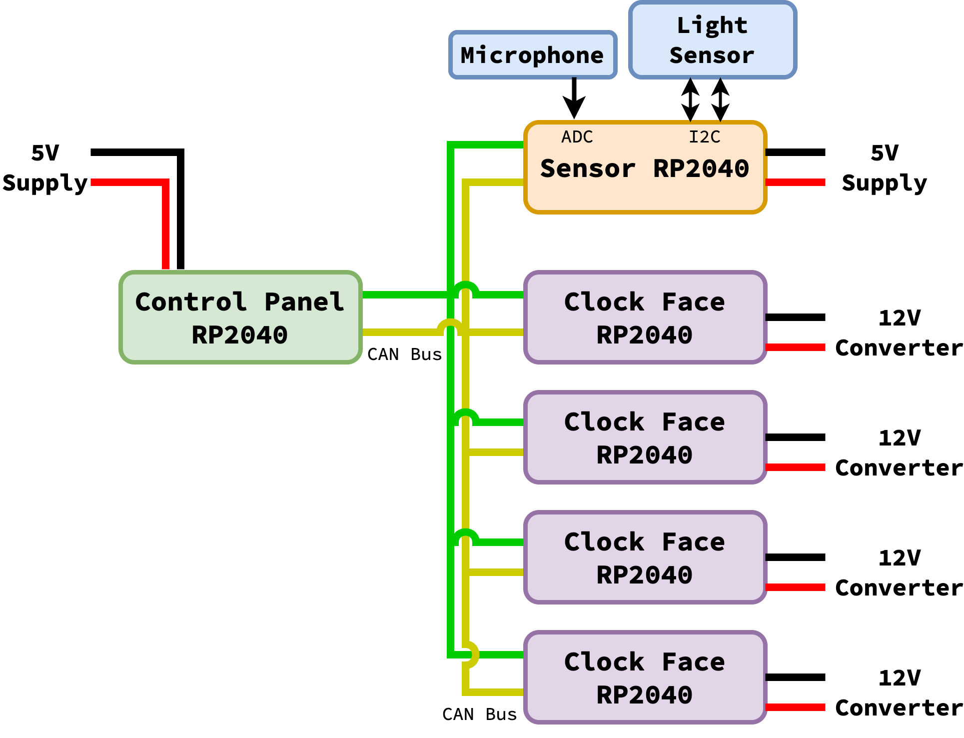
Our system was composed of three types of board:
A controller board (located at the main playing level, acting as the primary user interface)
A sensor board (located in the belfry for collecting sensor measurements)
Four face boards (located in each clock face for driving the LEDs)
All of these boards communicate over a shared CAN bus for reliable communication of information. While both the control and sensor board have access to an outlet (and can be powered through a 5V DC power supply), all of the clock face boards will rely on pre-existing 12V DC power converters already installed in the tower. For our project, we chose to use a Pico W for each board, as opposed to just a Pico, to allow for WiFi communication (as well as Bluetooth, should future groups choose to expand the system using the same hardware).
Different Supplies
The different power supplies and corresponding absolute voltages could theoretically provide communication issues by referencing different grounds; however, CAN communication relies on the difference between two lines, so absolute differences in supply voltages will not impact our network.
LED Setup
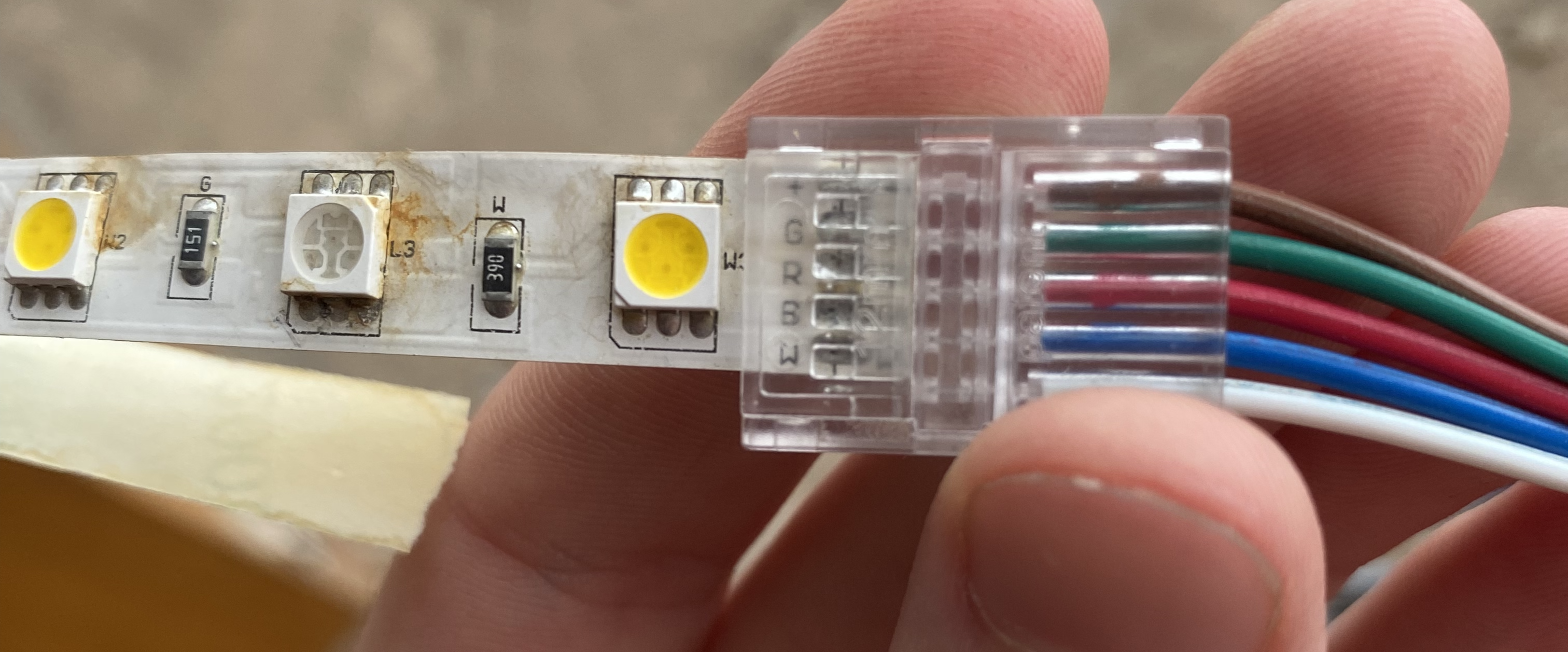
The clocktower currently uses strips of RGBW LEDs
to light the clock faces. These LEDs have 5 pins: +12V, R, G,
B, and W. We suspected this meant that the non-power lines should
PWM’d to ground to adjust the amount of that color; after probing these
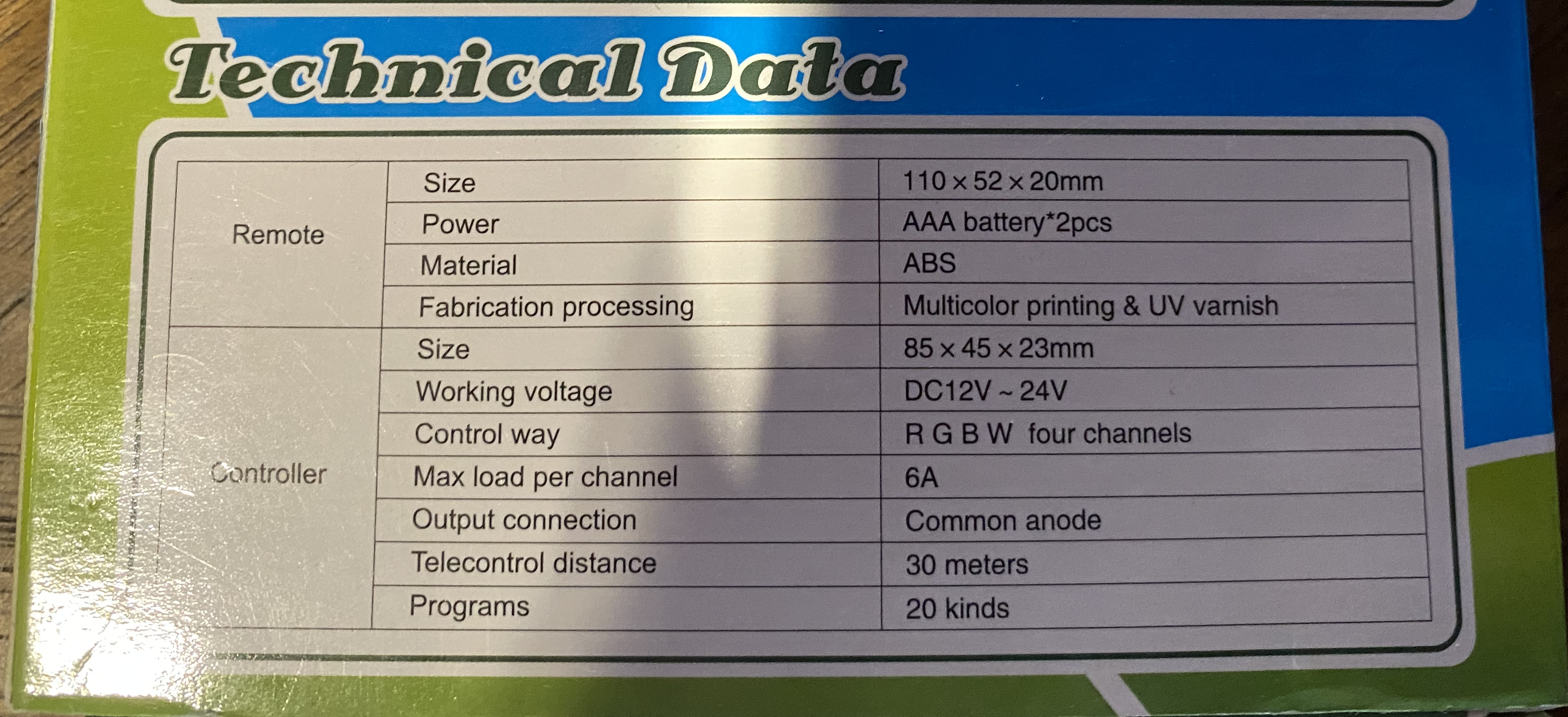
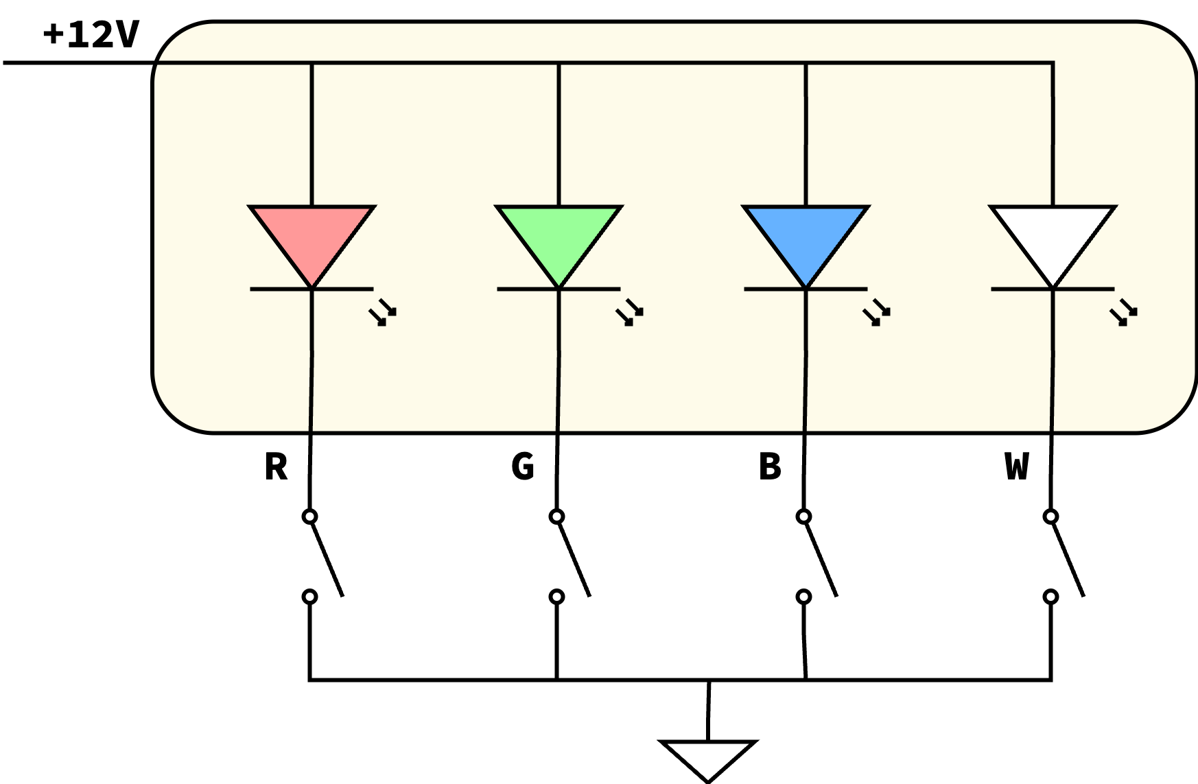
lines, as well as getting hints from the “Common Anode” marking on the
box, we confirmed that this was the case, with the model below showing
the strips in beige (anticipating connecting them to some form of switch)
One other consideration we had to make was the PWM frequency; too slow, and the blinking would be observable to viewers. However, after probing the current LED PWM output, we found the period to be about \(7.5ms\) (corresponding to a frequency of \(\sim 133Hz\)), which is easily attainable by our PWM channels (set to around \(4kHz\)) and our MOSFETs (which have rise and fall times in the tens of nanoseconds).
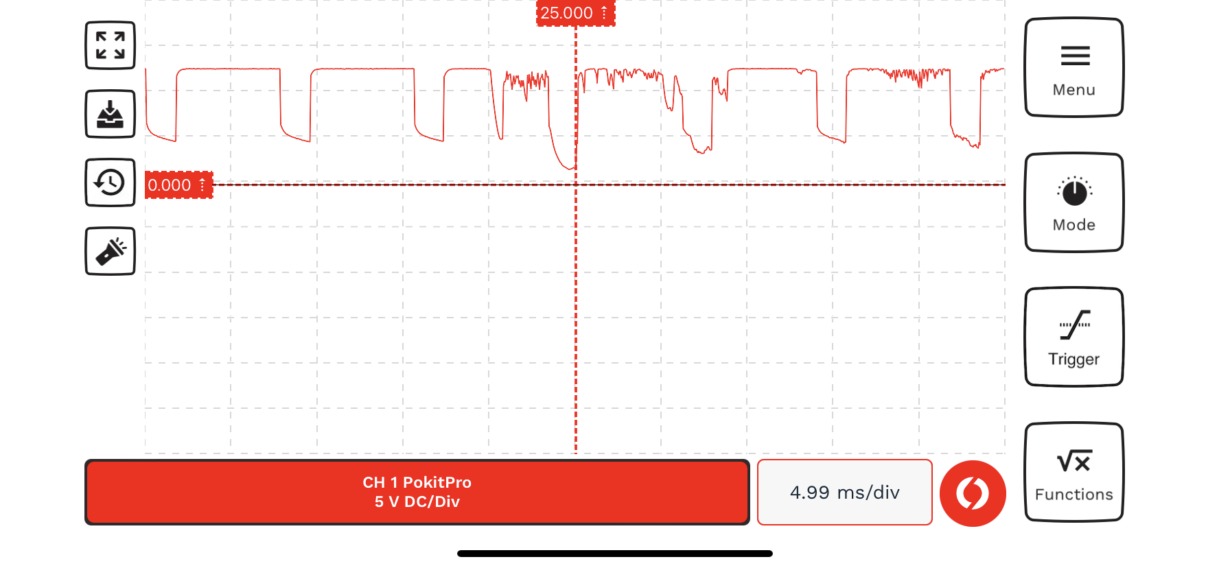
Probe output of an LED currently installed, with \(7.5ms\) between repeating patterns
CAN Transceiver
One particularly hardware-intensive component of our system were the CAN transceivers; these were present on all boards to communicate over the shared CAN bus. We chose to use the SN65HVD230DR transceiver, as it had already been used in a CAN bus demo from Professor Adams, allowing us to re-use the PIO program and accompaning C code (albeit modifying as an object-oriented class for reusability across programs for all the boards).
Aside from the transceiver itself, some other components are needed, including:
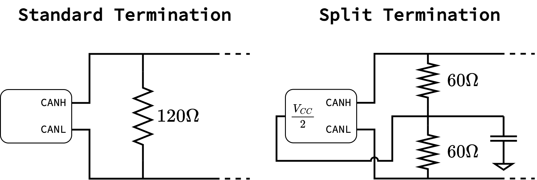
Terminating Resistors: Resistors are needed to pull the bus lines together by default. While terminating resistors are strictly only needed at the two ends of a bus, we wanted our system to be able to handle any configuration of connected boards, and accordingly terminated at all nodes of the bus. Additionally, CAN buses usually have standard termination (a \(120\Omega\) resistor between the two lines); however, we opted for split termination, which uses two \(60\Omega\) resistors instead to insert a capacitor between the two lines, to low-pass noise. Our transceiver additionally supported this by providing a \(\frac{V_{CC}}{2}\) output to connect to the midpoint and further stabilize the bus
TVS Diode: A Transient Voltage Suppression (TVS) diode was placed between both bus lines and ground, preventing large voltage spikes from damaging other electronics
Slope Control: Our particular transceiver provided a pin which allowed the device to be in low-power mode (pulled to \(V_{CC}\)), in “high-speed” mode (pulled to ground), or in “slope-control” mode (a resistor between the pin and ground), where the slope of transmissions could be controlled by the resistor’s value. Since we valued data integrity more than speed, we chose to have the transceiver in “slope-control” mode by providing a \(10k\Omega\) resistor, with an additional PMOS above to allow the microcontroller to turn off transmissions by pulling the node high, such as during setup to avoid noise
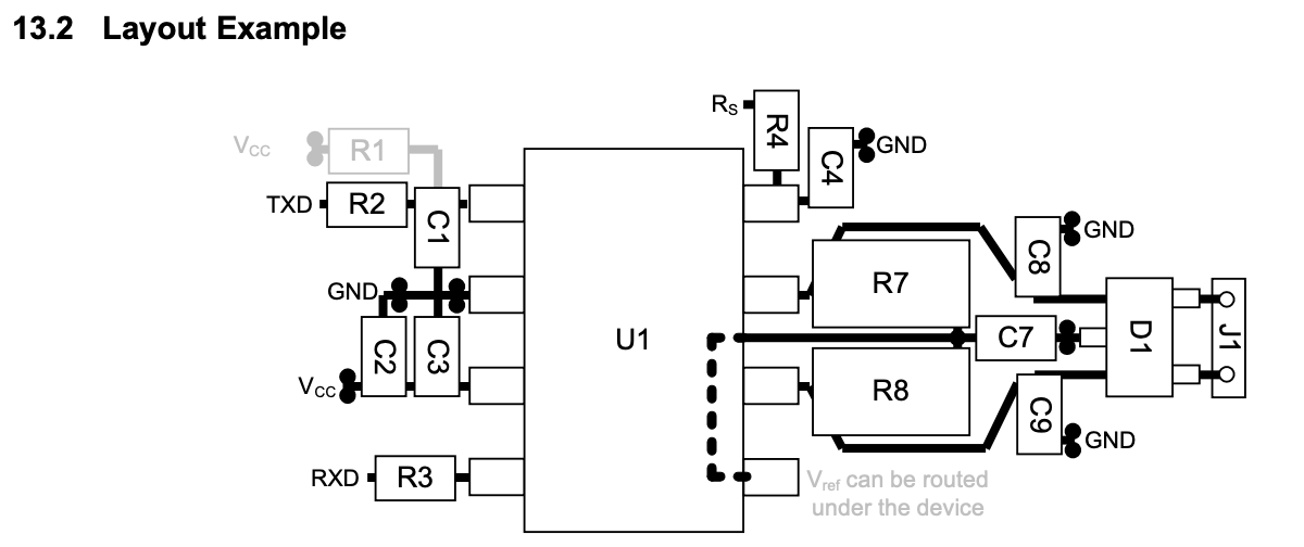
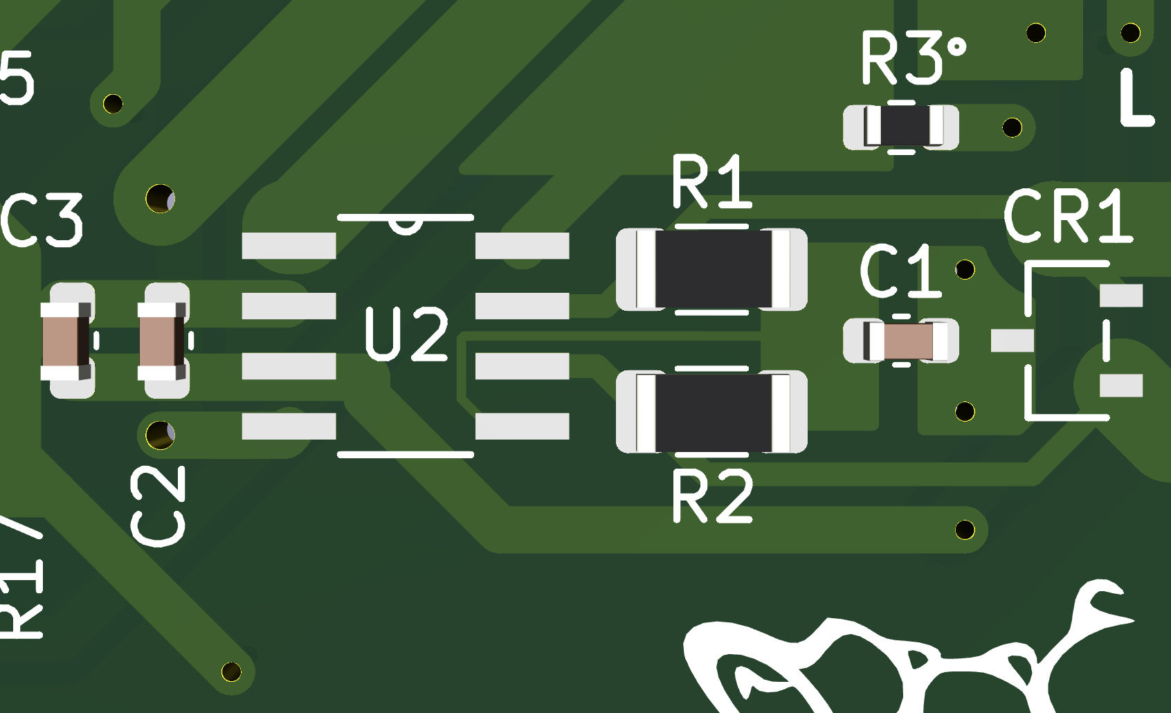
This diode (D1), as well as the split termination resistors and
capacitor (R7/R8/C7) and smoothing capacitors (C2/C3) can be
seen in the example layout below from the CAN transceiver datasheet,
which was utilized when implementing all boards (with the screenshot
below shown from the controller board):
Controller Board
The control board is the primary interface to the overall system. It should allow users to easily change the colors, as well as the “mode” of the LEDs, including being unconditionally on, pulsing with audio, or turning on and off with ambient light. Accordingly, the board features:
3 potentiometer sliders to control the amount of each color. LEDs of the corresponding color are situated above each slider to give a visual indication of how much of each color is present; this is done by using PWM to control the perceived brightness of each LED, with each LED connected to a separate PWM channel
A CAN transceiver connected to 5 pairs of outputs (in a
1x10screw terminal block) for communicating with all other boards.Switches to turn the board on and connect to WiFi, as well as a rotary switch for controlling the LED mode. Additional LEDs show whether the board is on and connected to WiFi
Sensor Board
The sensor board lives in the top of the tower, and is responsible for providing data about the amount of light and sound it detects. It includes an ambient light sensor and a microphone, as well as a CAN transceiver to communicate the data to the controller board.
Face Board
Finally, a face board lives in each of the clock faces. These boards are responsible for receiving the target color from the controller board, and adjusting the PWM duty rate for each of the LEDs appropriately. Accordingly, they contain 4 high-power MOSFETs (one for each channel to PWM), a CAN transceiver, and 2 LEDs to indicate both power and communication with the controller board. To connect to the LEDs, we noticed two controllers currently being used per face due to the single strip output from them; to alleviate this, each face board has two terminal blocks that each provide the 5 connections necessary for the LED strip.
Unlike normal LEDs, the LED strips are particularly high-power; while we couldn’t find the exact part number for the strips, the manufacturer’s website indicates that they could draw over an amp per meter, with a similar product by Adafruit indicating up to 1.6 amps per meter. While we couldn’t get an exact length measurement of the already-installed LEDs, the controller indicated a maximum load of 6 amps per channel, with the 12V voltage converters indicating a maximum of 24 amps (sufficient for the 4 channels). Accordingly, we chose our high-power driving MOSFETs and corresponding trace widths to be sufficient for 6 amps; our MOSFETs could handle up to 62 amps, and the traces were calculated for slightly over 6 amps via KiCad’s trace calculator (perhaps being able to handle a bit more), giving us confidence that they would work well with the current setup.
Hardware Difficulties
During the implementation of these boards, we ran into several unusual difficulties.
Face Board Shorting
When initially testing our boards, we noticed that one of the face boards
caused our power supply to produce a “whine”. After investigating, we
found an unusually low resistance between VSYS and GND of the
Pico on board; other boards had this around \(4k\Omega\), but the
offending board had around \(12.8\Omega\) between these two pins,
likely acting as a short and causing excessive current draw. Given that
it only occurred on one board, it seemed unlikely (although possible) to
be an issue with the board, but rather the soldering; however,
thoroughly desoldering and even drilling out the connection between these
pins proved unable to remove the low-impedance connection. While the
other boards were sufficient for a system demonstration, remedying this
board will be necessary for all four faces to be operational beyond this
class.
CAN Jump-Starting
When initially connecting the CAN transceivers between the boards, we expect both:
A board’s messages to be seen by other boards (when connected)
A board’s messages to be seen by itself (all the time)
However, our boards were strangely unable to initially receive either type of message when powered on. However, a strange remedy was found to this issue; if the two CAN lines were shorted together briefly, both types of messages would be received by the boards. Our current hypothesis is that there is some initial deadlock in the CAN bus’ PIO implementation that a temporary short is able to alleviate. While we can still demonstrate communication, our system should ideally be able to start up on its own, especially if a restart is required (by a watchdog timer or power fluctuations, for example).