ECE 5740 Final Lab:
Virtual Pinball with Sonar and Muscle IR Inputs
Team Members: Tianqi Hu (th737), Kedar Johnson (kj349)
For our final project, we designed a virtual pinball machine where the flippers are controlled using two sonar sensors and the ball is launched using an IR sensor configured to read bicep contractions. By waving a hand in front of the two sensors and flexing the arm with the IR sensor strap, one can play this more active variation of pinball. An overview of the project can be found in this video.
This project builds on our Galton Board lab by transforming a physics-based simulation into a fully interactive pinball machine. Rather than relying on conventional controls, we reimagine pinball as a physically driven experience where the player’s own movements directly control the game.
Our digital pinball machine features a variety of obstacles, including pegs, rectangles, rhombuses, and triangles. We explore different approaches for detecting collisions with these different geometries and for applying appropriate collision physics to update the ball’s motion in real time.
We further extend the hardware implementation by incorporating two sensor systems: ultrasonic distance sensors for flipper control and an infrared sensor circuit for ball launching. To enhance game play experience, we also add continuous background music and a discrete “ding!” sound effect triggered by collisions, implemented using direct memory access to enable CPU-free audio playback.
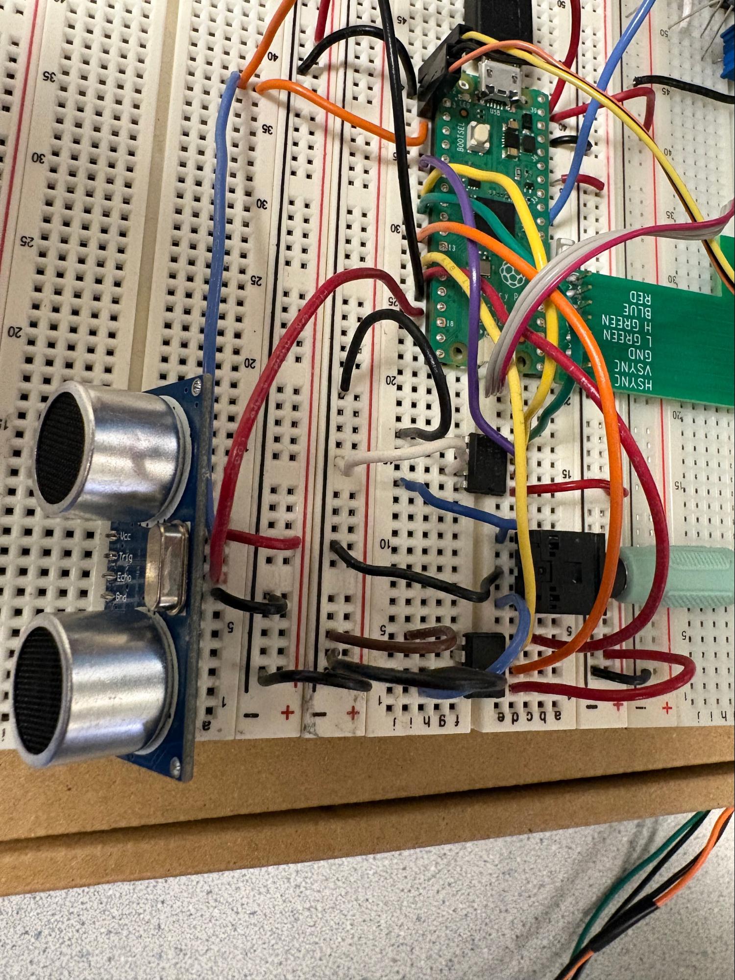
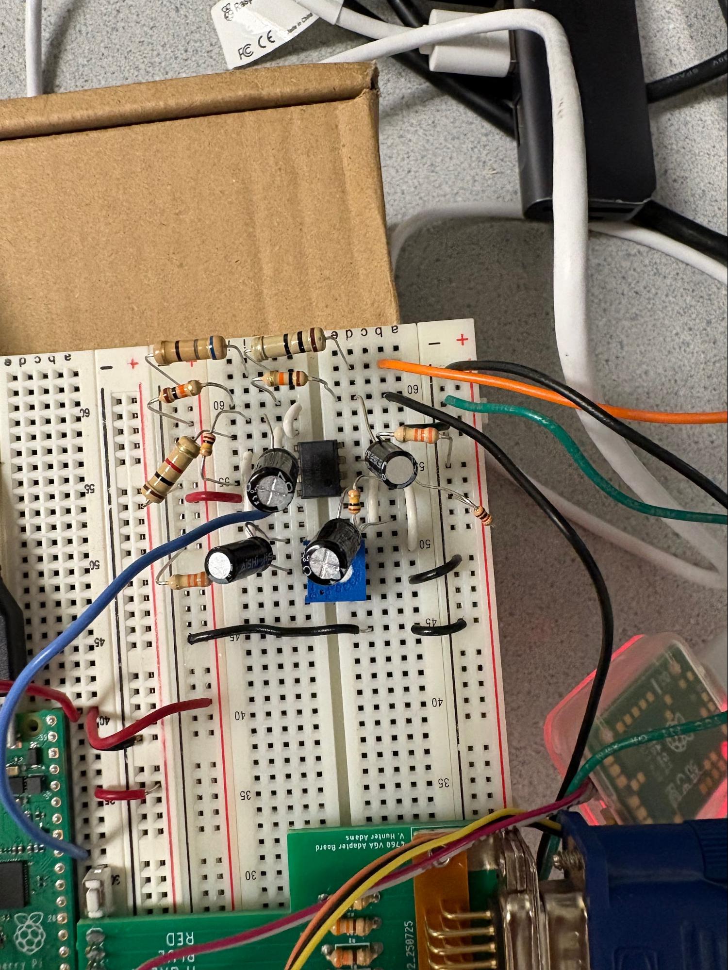
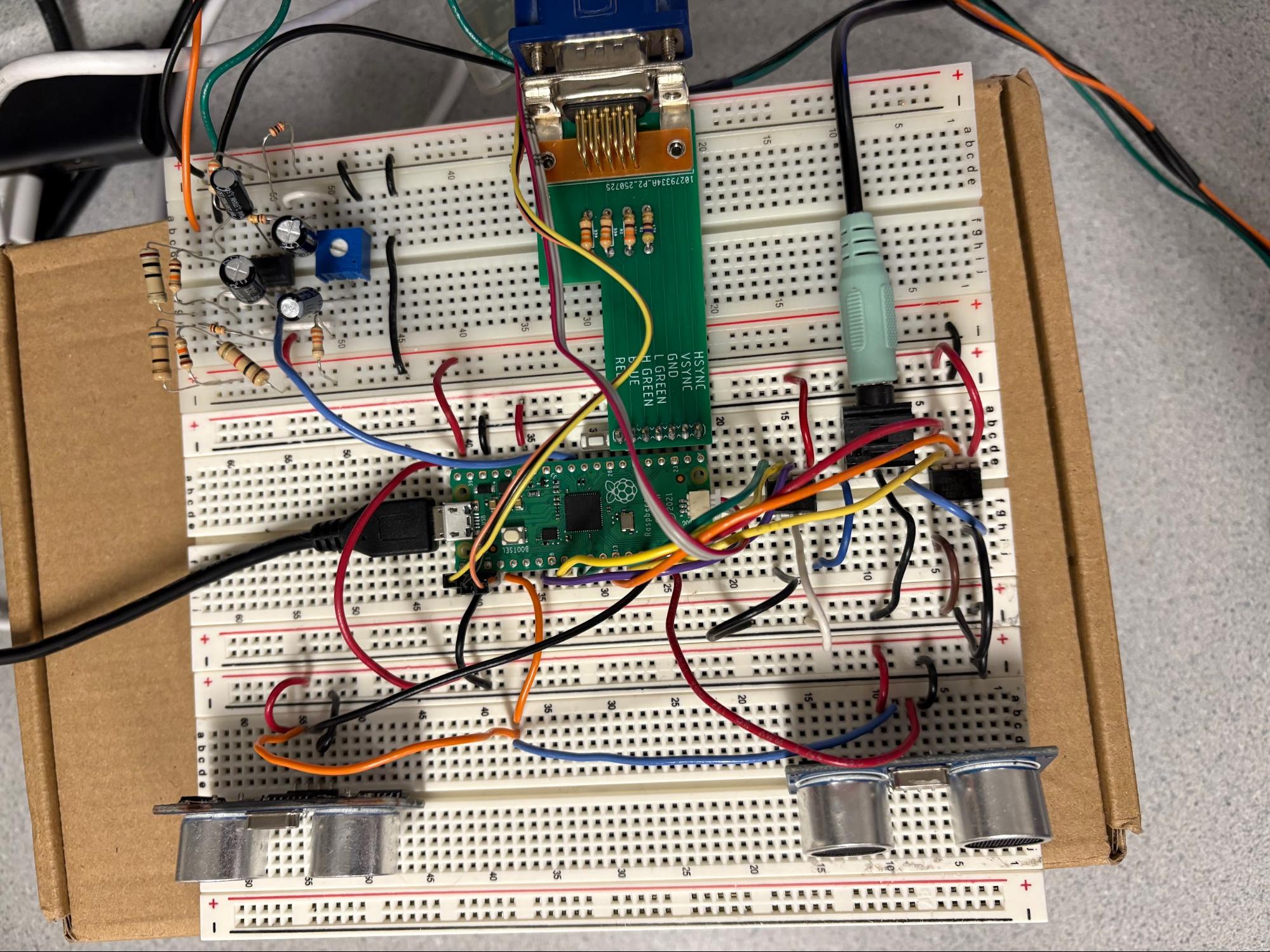
A top level view of our system is shown below:
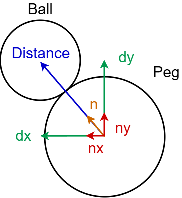
Our second lab focused on collisions with pegs. These objects had a surface with uniform distance from the center point, so distance between the ball and the peg and normal vectors could be calculated from the peg’s center.
This helps to prevent clipping through objects in the simulation, since a collision is detected when the distance between the ball’s center and the peg’s center is less than the sum of their radii. This is checked again by calculating the intermediate and checking if this value is greater than zero.


This essentially checks the ball's trajectory with respect to the peg’s center by comparing the magnitude of these x-components and y-components. When the velocity of the ball is directed towards the peg’s center the intermediate will be positive, otherwise, it is zero or negative.
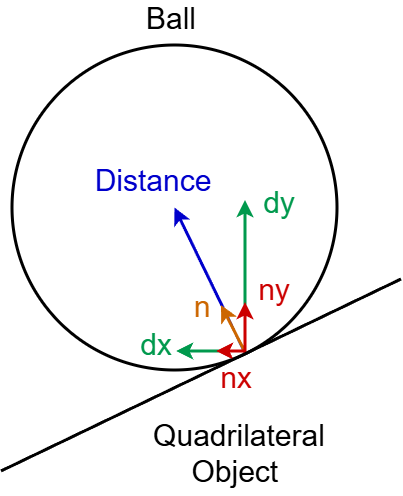
The issue for collisions with quadrilateral objects is their non-uniform perimeter distance from their centers. This makes practically any normal vectors originating from the center incorrect for collisions with these objects. The natural adaptation is to calculate normal vectors from the perimeter lines.
While this method is practical, it has a key limitation: missed or late collision detection when the ball moves too quickly. Because collisions are only checked once per frame in the interrupt service routine, the ball can “tunnel” from outside an obstacle to already past its boundary in the next frame. In that case, when we compute the surface normal using the ball’s current (inside) position, the normal points from the collision point inwards of the obstacle to the ball. The intermediate check then treats the ball as moving away from the obstacle, so no collision response is applied and the ball continues through the object.
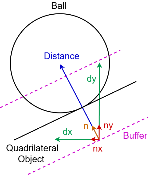
The solution we used is to apply a buffer in the collision calculations such that the point where the distance and normal vector are calculated from is offset into the object. This helps preserve the normal vector’s direction and the intermediate’s polarity when a collision is detected while the ball’s center is within the object.
The buffer is a function of the ball’s velocity so it can be large enough to stop major clipping when the ball is fast and small enough to prevent a false collision when the ball is slow. A false collision occurs when the ball is detected as colliding before it meets the object’s perimeter due to the extended range provided by a constant buffer.

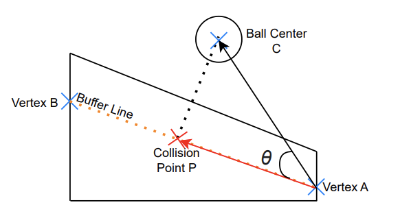
Collisions with quadrilateral objects are calculated by finding the point of collision along the buffered perimeter. To find this point, we project the position vector to the ball’s center with respect to one of the object’s vertices, A, onto the perimeter from A to another vertex, B. This will give us the vector from A to the collision point P.


Note that for collisions with diagonal line segments, we only apply the buffer to the y components for two reasons. First, it will also offset the x component of distance due to the angle of the perimeter. Second, acceleration between collisions is completely due to gravity, so very often the y component of velocity is intense enough to risk clipping. From this collision point with an applied buffer, we calculate the distance to the ball’s center.

We then calculate the normal vector and intermediate the same as for a peg and check that a collision occurs.
The process for horizontal and vertical lines is straightforward. Since the perimeter is parallel to the x or y axis, we can simply use the ball’s x coordinate for horizontal lines and y coordinate for vertical lines to find the collision point.


When a collision is confirmed, we shift the ball out of the object in the normal vector direction with a magnitude of collision distance + 1 pixel.


 )
)
Then, we update the ball’s velocity and apply a 0.75 bounciness factor.


Should either component of the resulting velocity exceed the magnitude of a constant max_velocity (35 pixels per frame at 30 FPS), we reduce it to equal the max. This value was chosen based on testing, where above this we observed some clipping and similar issues despite buffering and other countermeasures.
Collisions with flippers differ from collisions with stationary obstacles because they are rigid-body collisions involving a rotating body rather than interactions with a stationary surface. Therefore, once a collision with a flipper has been detected, we compute the collision physics separately.
The flippers undergo rigid-body rotation and therefore have nonzero surface velocity at the point of contact, which means the collision must account for momentum and energy transfer from the rotating rigid body to the ball. This allows the flipper to actively impart velocity to the ball, rather than simply reflecting its incoming motion.
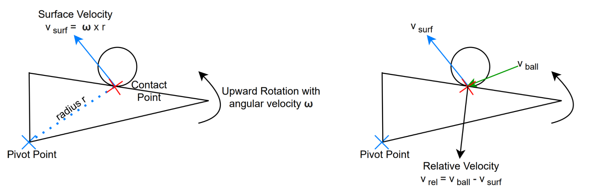
At the moment of impact, we first find the surface velocity of the flipper at the contact point. Next, we find the relative velocity of the ball between the ball velocity and surface velocity. This transforms the collision into the flipper’s local frame, where the contact surface is momentarily at rest and standard rigid-body collision physics can be applied.
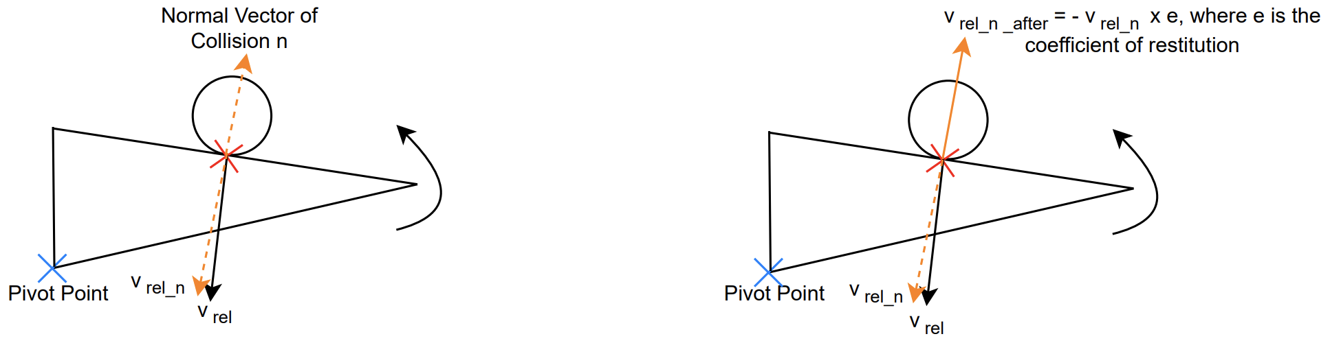
The relative velocity is then decomposed into normal and tangential components. The normal component is what causes the collision, so we apply collision physics to this component whereas the tangential component remains constant throughout the collision.
The velocity along the normal is dependent on the coefficient of restitution, which models how elastic the collision is. In our case, since large velocities cause the ball to clip through obstacles, we set the coefficient value to 0.1. We flip the direction of the normal component and then apply the coefficient of restitution.
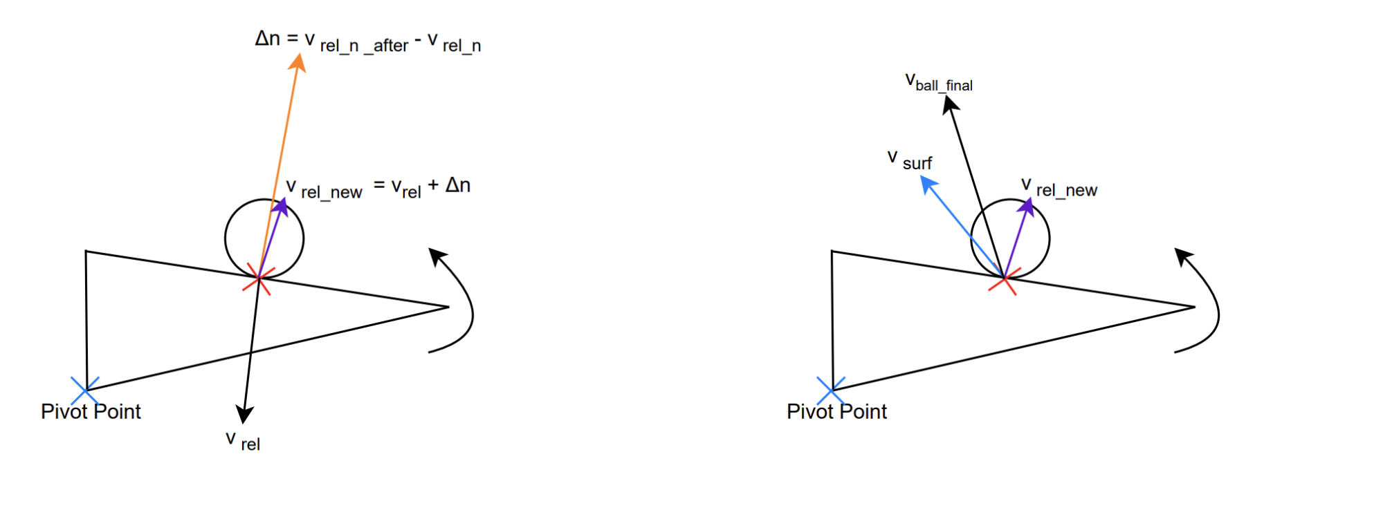
Next, we calculate the change in the normal component of the relative velocity, ∆n, and add it to the pre-collision relative velocity to obtain the new relative velocity after the collision.
Finally, we find the final velocity of the ball after the collision. Since the surface velocity of the flipper has not changed, we can calculate the ball’s world-frame velocity by adding the post-collision relative velocity to the flipper’s surface velocity at the contact point.
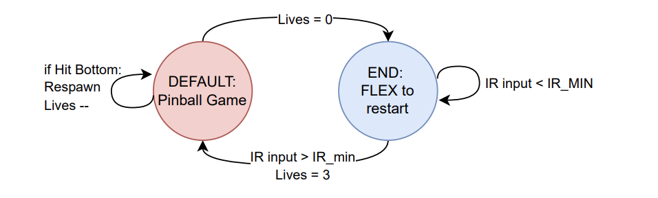
The animation thread changes the game state to end when the ball hits the bottom boundary and lives are reduced to zero. In the end state, the animation thread displays the highest score for the most recent play through and a prompt to flex to restart. The sonar thread yields during end state and the IR thread waits for a signal above its threshold before switching the game state back to default and resetting lives and highscore.
The animation thread calls all functions for drawing the VGA display except for the flippers which are drawn in the sonar thread. Everytime this thread runs, it starts by checking the game state. In the default state, if it has just switched from the end state then it sets all pixels to black (0) using fillRect() across the entire screen.
Next is updating the ball position. The thread will assign the ball’s current position to local variables and erase the pixels displaying the ball by setting them black with drawBall(). The drawBall() function simply takes the ball’s x and y coordinates and a char indicating color as parameters and calls fillCircle() with all of the drawBall() parameters in addition to the global value indicating the ball’s radius (8). If the ball is not set to relaunch, then ballMotion() is called with the memory address for the ball struct as an input. This is where collision calculations and position updates between frames are completed. Next, the animation thread calls wallsAndEdges() to check collisions specifically with the boundaries. With all changes in the ball’s position resolved, the thread’s local variables for the ball’s position are updated. The ball is redrawn after all other drawing functions in the thread have been called.
drawBackground() is called to draw the borders and most of the background visual effects. First, this function calls drawLine() twice to draw the slanted edge in both upper corners, drawVLine() to draw the divider for the launch chamber, and drawRect() to draw the top, left, right, and bottom borders.
Next, variables for the circle effects around the pegs are defined including the initial radius (30), the minimum radius (15), a temporary radius (starting at initial radius), and a temporary color (starting at the global color index value). In a while loop that continues as the temporary radius shrinks from initial to below the minimum, a circle is drawn centered at each peg with a radius equal to temporary radius and color determined by the temporary color. Every loop, the temporary color is also cycled through 16 colors.
Continuing, drawBackground() assigns three temporary color variables with color indices that are 1 apart (from 0 to 15 in a loop). drawStar() is called three times with fixed center positions, preset lengths, and temporary color variables in descending order as parameters. drawStar() starts by calculating two radii for its farthest and closest points using the length parameter and a 0.382 scale down constant. This function then implements two arrays to hold the x and y coordinates for 10 points/corners and assigns them in a for loop using sin and cos tables to step through 36° intervals. In another for loop, drawLine() is repeatedly called with each point and its neighbor as parameters to draw all 10 edges. The result is a complete star, and drawbackground uses this to draw three descending stars of progressively increasing sizes at the lower center of the VGA display.
Finally, drawBackground calls drawTrianglePairs() with the number of triangles as a parameter. drawTrianglePairs() checks which triangles to “turn on” based on a global variable called blink frames that functions as a frame counter. It divides the current value of blink frames by a length of time to hold the same triangle pair indicated by the variable hold frames (8 frames). This is further broken down into intervals of 6 in a variable called active index to indicate each pair. In a for loop, the function checks which pair to turn on, and for that pair, it sets a temporary color variable to pink. For all other pairs, the color variable is set to black.
Within these loops, drawtriangle() is called twice with corner positions for both triangles in the pair and the temporary color value included as parameters. drawTriangle() uses the input parameters to call drawLine() three times to draw or erase a triangle depending on if the color input is pink or black. This creates a flashing pattern of triangles that points along the top of the rhombi towards the space between flippers.
The animation thread calls drawObstacles() next to print all obstacles. In this function, all rectangle objects are drawn with fillRect(); all pegs are drawn with fillCircle(); both rhombuses are drawn with drawVLine() twice for the sides, drawHLine() for the bottom, and drawLine() for the slanted top. Each object has preset positions and sizes, and each group of objects has preset colors.
We then call drawInfo() to print the game information in the top left corner. This function starts by clearing the space with a black fillRect() and setting text and cursor parameters. All text prints use snprintf() to prepare variable conversions to strings and writeString() or writeStringBold() to print to the VGA display.
drawInfo() prints “Lives :” and in a for loop ending when the loop index exceeds the number of remaining lives, the function uses drawChar() to draw hearts that indicate these remaining lives. drawChar() is given a position defined in each loop, the ASCII code for a heart (0x03), the char for red (8), the char for black (0), and text size (1) as parameters. Afterwards, the cursor and text color are readjusted before printing the current score and high score with cursor adjustments in between prints.
Here is where the global variable blink frames increments up by 1. If blink frames is a multiple of the global constant hold frames then the global variable color index is also incremented up by 1. In ballMotion(), whenever a collision occurs with objects other than the rhombi, launch divider, and flippers, a global variable star blink counter is assigned a value equal to the sum of the constant number of frames to hold white and the constant number of frames to hold yellow (22).
In the animation thread, if the star blink counter is greater than 0 then while it is greater than the global constant for the number of white frames it will call blinkStars() with the color index for yellow (11) as a parameter. Otherwise, if the star blink counter is greater than 0 then it will call the same function with the color index for white (15) as a parameter. If the star blink counter is 0 or less, then the same function is called with black as the parameter.
blinkStars() calls the drawStar() function 5 times with 5 positions along the top of the display. Each star has matching lengths and colors based on the parameter for blinkStars().
If relaunch is enabled, then the animation thread calls relaunchCountdown() instead of ballmotion(). relaunchCountdown() prints an instruction telling the user to flex which will create an IR muscle sensor signal that triggers a ball launch. This function also prints a countdown that starts when the global variable relaunch counter starts decrementing. This function clears the allocated area with a black fillRect() 0.25 seconds before the countdown ends and the ball launches
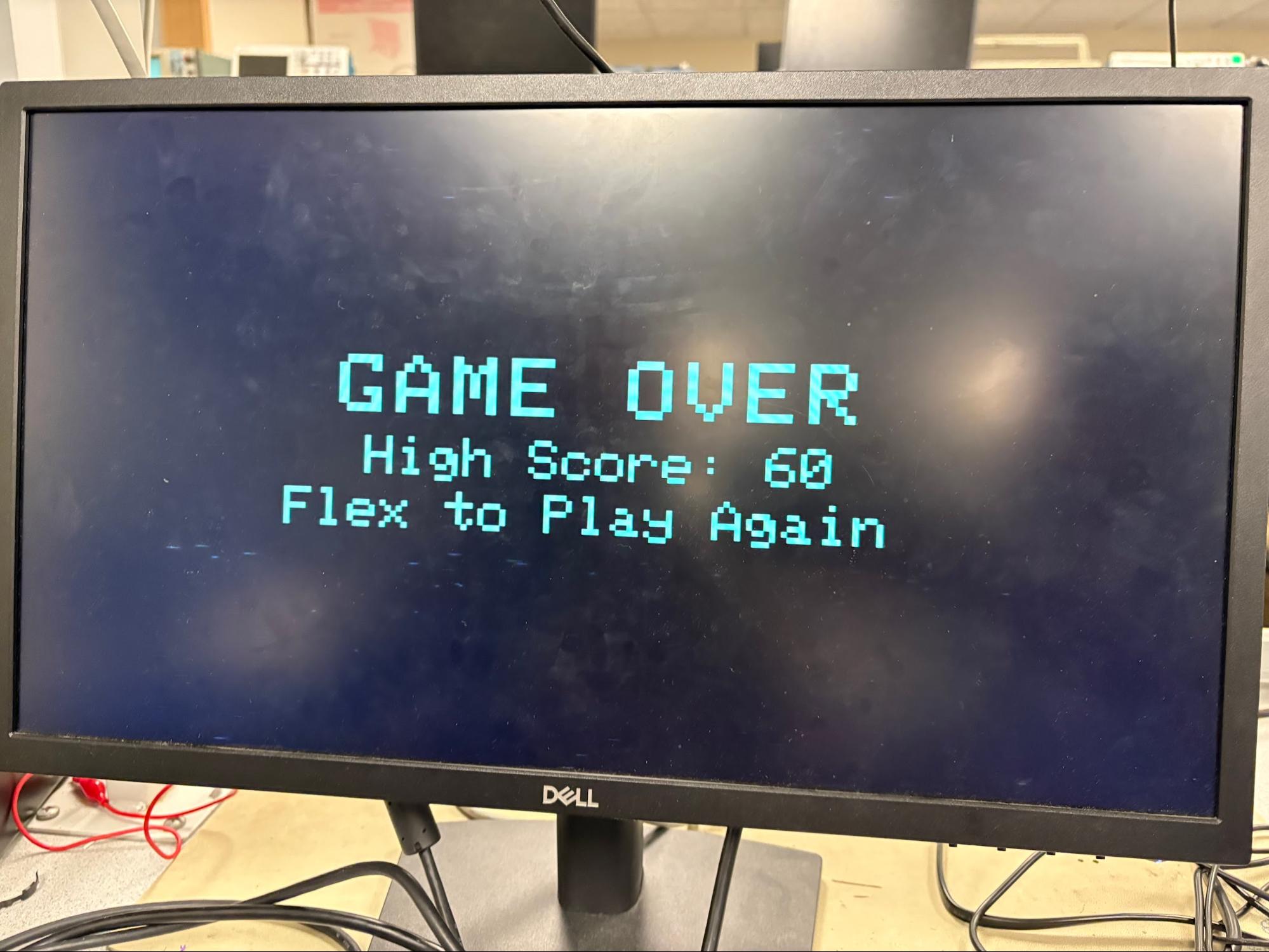
When the game state is set to end state, the animation thread will only call drawEndScreen() once and do nothing else until the game state is changed back to default in the IR thread. drawEndScreen() clears the whole VGA display with a black fillRect(). It then prints a large game over message including the high score for the most recent play through. Last, this function prints a prompt to the user to flex to continue playing.
Two sounds are to be generated: the first is the background music for the game, which should play throughout the time the pinball machine is active. The other sound should be a classic “ding!” sound when the ball collides with an obstacle, similar to a real pinball machine. Unlike in previous labs, however, these sounds are not easily synthesized by way of simple sine waves. Therefore, we use music found online and download them as wav files, which we then convert to DAC-compatible data.
Our first approach was to use the same SPI channel (SPI0), and have 2 sets of control and data channels that feed data to the SPI channel. The “ding!” control channel would only start when a collision is detected, and write the sound data to the SPI. On the other hand, the background music control channel would be chained to its data channel, which would mean background music data is constantly being fed to the same SPI.
The DAC takes in digital data in 16 bits: the first 4 bits determine which DAC channel the analog signal will be output from, either channel A or B. We also set this up such that the “ding!” data had channel A configuration bits whereas background music data was configured with channel B’s bits. This way, data from both music streams could be output to different channels on the DMA and different speakers.
However, this setup did not produce the expected audio output. Instead, we observed heavily distorted sounds from the speakers. Although the SPI peripheral transmits data to the DAC at the correct audio sampling rate of approximately 44 kHz, sharing a single SPI interface between two independent DMA streams caused contention at the SPI transmit path. While the SPI includes a transmit FIFO, it does not provide arbitration or timing guarantees between multiple DMA sources. As a result, audio samples from the background music and the “ding!” sounds were interleaved in time rather than mixed, violating the uniform sample timing required by the DAC. This introduced significant timing jitter and led to distorted sounds.
As such, a simple hardware fix was to use an additional DAC and utilize both SPI peripherals, such that each audio stream is driven by its own dedicated SPI channel. GPIO pins 4–7 were configured for SPI0, while pins 8–11 were configured for SPI1. This separation eliminated timing contention between audio streams, allowing each DAC to receive samples at a stable and uniform rate and resulted in clean music playback.
However, another issue that arose from this implementation was that the VGA display would briefly appear to “shake” during collision events. This occurred because both the VGA subsystem and the audio playback rely on DMA, and a collision triggers additional audio DMA activity. The resulting contention for shared bus and memory resources introduced small delays in the VGA pixel transfers, causing temporary timing irregularities. A fix for this was to increase the clock speed of the RP2040 to 250MHz, allowing DMA transfers to occur faster. This reduces the impact of contention between the VGA and audio DMA channels, and the VGA display was able to run as normal.
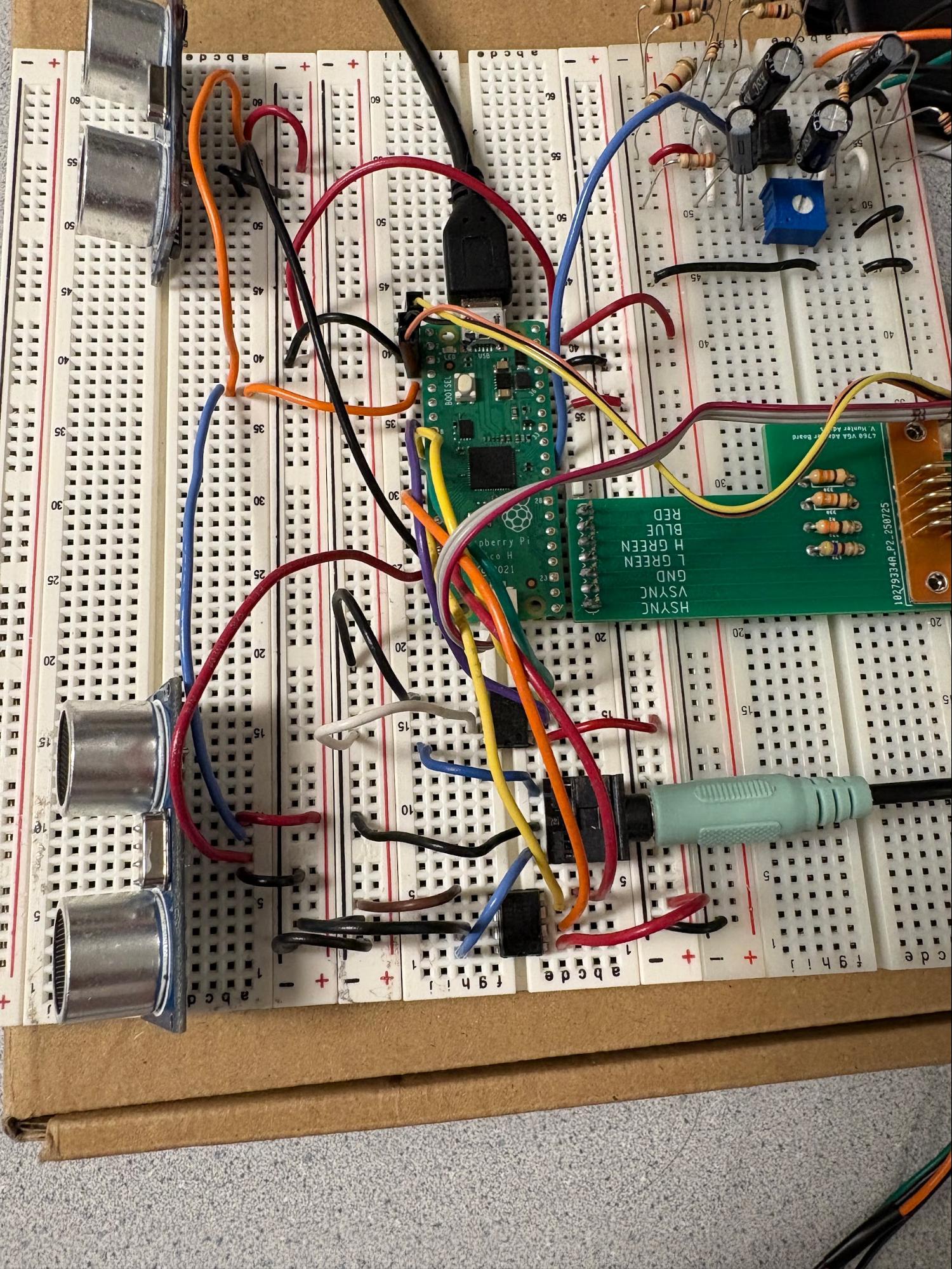
The total circuit is made up of three main sections for handling the IR muscle sensor, the dual sonar sensors, and sound generation.
Two ultrasonic distance sensors were used to control the flippers on the pinball machine. These sensors measure the distance between the sensor and the nearest surface, and moving closer to the sensor would cause the flippers to move upwards, whereas moving away would cause the flippers to move downwards. We used HC-SR04 sensors equipped with ultrasonic transmitter, receiver and control circuits.
The sensor is triggered by a 10 microsecond pulse, after which the sensor sends out 8 cycles of ultrasound bursts at 40 kHz to detect surfaces. After detection, it sends out an echo pulse that varies in width: a surface further away returns a longer echo pulse and vice versa. The formula for calculating the distance (in centimetres) is: echo pulse period/58.
Following the data sheet instructions, the period of the trigger pulse should be larger than 60 microseconds, such that the trigger pulse and echo pulse do not overlap. We therefore chose a PWM frequency of 1kHz. To achieve this, we set the clock divide value to 250 (corresponding to a 1MHz clock), and as a result each PWM counter tick equals 1 microsecond. Next, we set the wrap value to 1000 so each PWM period is 1 millisecond long. Finally, we set the control value to 10 such that a pulse is only 10 microseconds long.
Next, we implement the code to measure the echo pulse. We do this by way of an IRQ, which is triggered both on the rising and falling edge of a pulse received on the input GPIOs to the echo pin on the sonar sensors. When a pulse is detected (rising edge), we enter into the IRQ and record the current system time and exit the IRQ. On the falling edge, the IRQ takes the difference between the current system time and the last measured system time to compute the width of the echo pulse, and updates a global pulse_width_us variable with the value. Finally, it sets a pulse_ready bool to true to signal to the sonar protothread that a new pulse has been detected.
The sonar protothread is responsible for calculating the detected distance and updating the position of the flipper on the VGA screen. It is only active if the pulse_ready bool is true; otherwise, it yields to the other threads. When a new pulse is detected, it computes the distance from the pulse_width_us variable, and checks if the distance is larger than 20cm. We chose 20cm to be the threshold through experimental testing. Any distance smaller than 20cm will mean that the user is close enough to be engaging with the flippers, so the flipper should be moving upwards. Otherwise, the user is far away and the flippers should move down. This gameplay sequence was found to be the most intuitive.
The flipper position is not mapped directly to the measured distance. Instead, the distance measurement is used only to determine the direction of rotation. The flipper itself rotates at a fixed angular speed (5 rad/s), which results in smooth and visually stable motion on the VGA display. This design prevents abrupt changes in user distance from causing sudden jumps in the flipper position.
Each frame, the flipper rotation angle is updated incrementally according to:

where  t is the frame period and
  is the constant angular velocity. Although the implementation specifies the update rate in terms of radians per frame, this corresponds to a true angular velocity of
  in radians per second. While the flipper is updated discretely once per frame, the angular velocity itself is defined in continuous time (rad/s). This explicit angular velocity is required later when computing collision physics, since the linear velocity of points along the flipper depends on the true angular velocity rather than a frame-based update amount.
The rotation values were clamped between a minimum and maximum, which corresponds to the range of y values the tip of the flipper could be drawn at. If the rotation values were different from the previous frame, the previous flipper triangle was erased and a new triangle was drawn onto the screen.
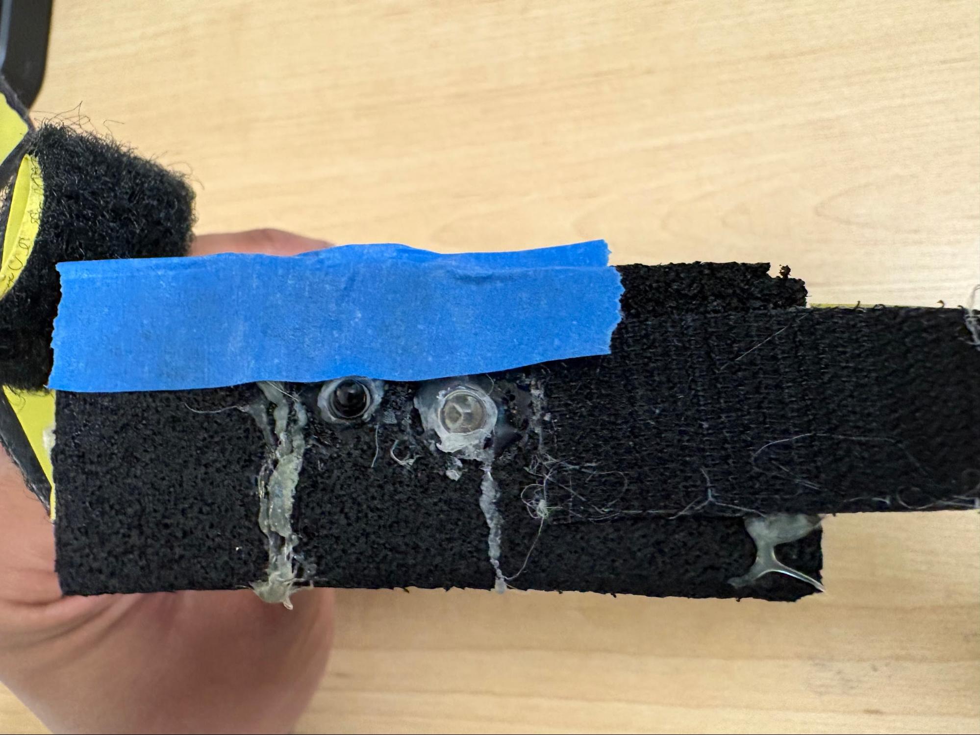
The IR muscle sensor is based on a prior student’s project where they compared the effectiveness of an IR sensor with an EMG sensor for measuring muscle contractions. The IR sensor uses an IR emitter to shine a beam at the target muscle. Some rays reflect off of the muscle fibers and shine back towards an IR phototransistor positioned next to the emitter with a divider in between them.
During a muscle contraction, there is a short period where the fibers are lengthened, a varying period of sustained force and fiber length, and a final period where the fibers slowly release and blood flows back into the muscle.[1] In the initial lengthening period, the muscle fibers are less reflective due to the stretched out state.1 In the final period, the fiber’s reflectivity increases beyond the resting state due to the blood flow.1
When the IR phototransistor is hit by these reflected rays, a signal of matching intensity is sent into the filtering circuit. With a bandpass filter and careful selection of resistance and capacitance values, much of the noise and artifacts can be reduced in the final signal.1 This also allows the signal from the initial lengthening to finish before the signal from the final period of returning blood flow starts.1 We send the signal from the final period of the contraction through GPIO 26 (ADC channel 0) where it is converted to a digital signal using the RP2040’s built-in analog to digital converter (ADC).
The ball launch velocity is controlled using the input signal from the IR muscle sensor and managed with IR thread. When the ball hits the bottom boundary, the IR thread is signaled to relaunch the ball. The animation thread will print a prompt to the user to flex for the IR muscle sensor along with a 3 second countdown.
Once the IR thread detects a signal greater than the constant IR_MIN (500 in 4095 ADC range) it will start a running summation of IR muscle sensor signals and the animation thread will start the countdown. This minimum value from the IR muscle sensor prevents weak signals from triggering the launch sequence.When the global relaunch counter reaches 12 or higher (3+ seconds), the IR thread will calculate the average IR muscle sensor input over that 3 second period.
If the average input is higher than the constant IR_MAX (1500 in 4095 ADC range) then it is reduced to IR_MAX, and if the average input is less than IR_MIN then the summation resets and the IR thread waits until it receives a signal from the IR sensor that is greater than IR_MIN again. This second IR_MIN check is a secondary measure to prevent brief, small muscle contractions from enabling the launch sequence.
The average IR signal is then converted to velocity on a scale such that IR_MAX converts to max velocity. The result is assigned to the respawned ball’s y-component velocity, and this causes the ball to launch. The relaunch sequence is ended and the launch counter and tally are reset before yielding.
When starting a new game (after losing and reaching end game state) the IR thread logic changes. Now when the input from the IR muscle sensor exceeds IR_MIN high score and lives are reset, the game state is switched to default, and relaunch is signaled to initiate the first ball launch.
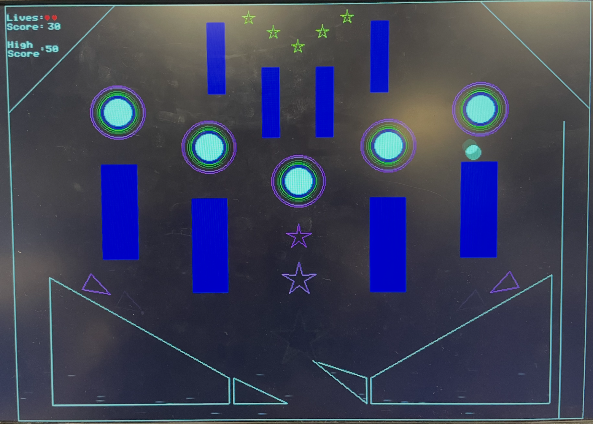
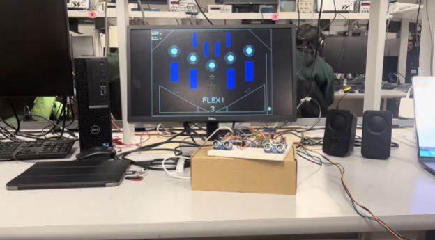
The pinball game as displayed on the VGA is shown below. It has 8 rectangles, 5 pegs, and 2 rhombuses as the obstacles. The two flippers at the bottom of the screen are used to push the ball back up the screen.
In the screenshot above, we show the instance where a ball has collided with the top of a rectangle. The shadow of the ball that appears is the previous position of the ball. The next position of the ball is correctly drawn: we see that the new position of the ball is just above the rectangle, which is in line with our collision logic that transports the ball just above the surface of the obstacle in event of a collision. Another hidden easter egg is shown: the stars at the top of the screen light up in yellow for a collision!
In general, the collision behavior of the pinball game is robust and visually realistic. Collisions between the ball and all obstacles are accurately resolved so that the ball never overlaps any surface. Upon contact, the ball is immediately reflected based on the local surface normal or surface velocity in the case of moving flippers. This results in motion that closely resembles a real pinball machine, and the ball motion feels responsive and predictable.
Flexing one’s muscles to launch the ball proves to be an engaging input mechanism; it provides a clear sense of physical effort and direct control over the ball’s initial velocity. The muscle sensor circuit has been set up such that even subtle changes in flexing strength cause a corresponding change in the measured signal. If the player flexes hard enough, the ball is launched with full force. Correspondingly, when the player is not flexing, the IR signal remains below the activation threshold, so the launch sequence and countdown do not begin until intentional muscle activation is detected.
As for the flipper control, the sonar sensors correctly trigger upward flipper motion when a person is close enough and return the flippers downward when no object is detected within range. With our design choice of using the distance measurement as a per-frame directional command rather than a direct position mapping, the flippers rotate up or down smoothly, resulting in a more polished gameplay.
These sensor controls provide a safe method for incorporating human movement into gameplay, as they rely only on passive sensing and do not require any electrical current to be passed through the body.
The music is played back reliably using DMA-driven audio output, and after utilising both SPI buses on the RP2040, both the background music and the “ding!” collision sounds can be produced at the same time, without any interruptions.
Finally, the game state of our system is well managed and the game over screen appears after all 3 lives have been used up. The high score of the 3 games is displayed on the screen, and the user flexes to play again.
To get a better understanding of how the game play is like, we invite you to watch the youtube video linked in the introduction.
Overall, designing this pinball machine game and coming up with inventive ways to include human movement into the gameplay was a rewarding process. We first started with setting up the sensor circuits, then moved to writing code for collision physics, and finally integrated all pieces to present a working pinball game. As we experienced the game ourselves, we iteratively refined its mechanics and interactions to improve responsiveness, stability, and overall user experience.
One area of improvement would be expanding the gameplay features to increase variety and engagement. For example, allowing more balls to be animated simultaneously or introducing multiple levels with different obstacle layouts would add depth to the experience and allow the system to go beyond the limitations of a traditional pinball machine.
Finally, we would like to thank Professor Hunter and Professor Bruce for their guidance and support throughout the project, including helping us to find safe and effective ways to measure human movement and integrate it into the gameplay design.
The group approves this report for inclusion on the course website. The group approves the video for inclusion on the course youtube channel.
Tianqi: Sonar Sensor circuits, Collision Physics, Game Design, Music
Kedar: IR Sensor circuit, Collision Physics, Game Design
Animation.c file:
/**
* Hunter Adams (vha3@cornell.edu)
*
*
* HARDWARE CONNECTIONS
- GPIO 16 ---> VGA Hsync
- GPIO 17 ---> VGA Vsync
- GPIO 18 ---> VGA Green lo-bit --> 470 ohm resistor --> VGA_Green
- GPIO 19 ---> VGA Green hi_bit --> 330 ohm resistor --> VGA_Green
- GPIO 20 ---> 330 ohm resistor ---> VGA-Blue
- GPIO 21 ---> 330 ohm resistor ---> VGA-Red
- RP2040 GND ---> VGA-GND
*
* RESOURCES USED
* - PIO state machines 0, 1, and 2 on PIO instance 0
* - DMA channels obtained by claim mechanism
* - 153.6 kBytes of RAM (for pixel color data)
*
*/
// VGA graphics library
#include "vga16_graphics_v2.h"
// Standard libraries
#include <stdio.h>
#include <stdlib.h>
#include <math.h>
#include <string.h>
// Pico libraries
#include "pico/stdlib.h"
#include "pico/divider.h"
#include "pico/multicore.h"
// Hardware libraries
#include "hardware/clocks.h"
#include "hardware/pio.h"
#include "hardware/dma.h"
#include "hardware/adc.h"
#include "hardware/pwm.h"
#include "hardware/irq.h"
#include "hardware/spi.h"
#include "hardware/pll.h"
// Protothreads
#include "pt_cornell_rp2040_v1_4.h"
// + + + + BEGIN ANIMATION CODE
char color_index = 0 ;
typedef struct {
int B1x, B1y;
int B2x, B2y;
int Tx, Ty;
int B1x_m, B1y_m;
int B2x_m, B2y_m;
int Tx_m, Ty_m;
} TrianglePair;
TrianglePair triangle_pairs[6] = {
{40,303, 49,286, 71,309, 600,303, 591,286, 569,309}, // 0
{76,324, 86,306, 107,330, 564,324, 554,306, 533,330}, // 1
{113,345,123,327,144,351, 527,345, 517,327, 496,351}, // 2
{149,365,159,348,180,371, 491,365, 481,348, 460,371}, // 3
{186,386,196,369,217,392, 454,386, 444,369, 423,392}, // 4
{222,407,232,389,253,413, 418,407, 408,389, 387,413} // 5
};
int cos1000[10] = { 0,587,951,951,587,0,-587,-951,-951,-587 };
int sin1000[10] = {-1000,-809,-309,309,809,1000,809,309,-309,-809};
static int blink_frames = 0;
static int hold_frames = 2;
void drawTriangle(int a_x, int a_y, int b_x, int b_y, int c_x, int c_y, int color){
int vert_length = b_y - a_y;
int hori_width = c_x - b_x;
drawLine(a_x, a_y, b_x, b_y, color);
drawLine(b_x, b_y, c_x, c_y, color);
drawLine(a_x, a_y, c_x, c_y, color);
}
void drawStar(int center_x, int center_y, int length, int color){
int outer_r = length / 2;
int inner_r = (outer_r * 382) / 1000; // integer 0.382
int px[10];
int py[10];
for(int i = 0; i < 10; i++){
int r = (i % 2 == 0) ? outer_r : inner_r;
px[i] = center_x + (r * cos1000[i]) / 1000;
py[i] = center_y + (r * sin1000[i]) / 1000;
}
for(int i = 0; i < 10; i++){
int j = (i + 1) % 10;
drawLine(px[i], py[i], px[j], py[j], color);
}
}
void drawTrianglePairs(int start_x, int start_y,
int axis_x,
int num_triangles,
float step, float h, float w)
{
int triangle_hold = 8;
int active_index = (blink_frames / triangle_hold) % num_triangles;
for(int k = 0; k < num_triangles; k++){
int color;
if(k == active_index){
color = PINK; // only this triangle pair is on
} else {
color = BLACK; // off triangles
}
int B1x = triangle_pairs[k].B1x;
int B1y = triangle_pairs[k].B1y;
int B2x = triangle_pairs[k].B2x;
int B2y = triangle_pairs[k].B2y;
int Tx = triangle_pairs[k].Tx;
int Ty = triangle_pairs[k].Ty;
int B1x_m = triangle_pairs[k].B1x_m;
int B1y_m = triangle_pairs[k].B1y_m;
int B2x_m = triangle_pairs[k].B2x_m;
int B2y_m = triangle_pairs[k].B2y_m;
int Tx_m = triangle_pairs[k].Tx_m;
int Ty_m = triangle_pairs[k].Ty_m;
// original triangle
drawTriangle(B1x, B1y,
B2x, B2y,
Tx, Ty,
color);
// mirrored triangle
drawTriangle(B1x_m, B1y_m,
B2x_m, B2y_m,
Tx_m, Ty_m,
color);
}
}
void drawBackground(){
// drawRect(4, 0, 635, 479, WHITE);
//draws the borders and the tunnel
drawLine(120, 0, 0, 120, WHITE);
drawLine(518, 0, 638, 120, WHITE);
drawVLine(611, 135, 479-135, WHITE);
drawRect(0, 0, 640, 480, WHITE);
// circles
int circle_radius = 30;
int min_radius = 15;
int r = circle_radius;
int local_color = color_index;
while(r > min_radius){
drawCircle(120, 120, r, local_color);
drawCircle(220, 160, r, local_color);
drawCircle(320, 200, r, local_color);
drawCircle(420, 160, r, local_color);
drawCircle(520, 120, r, local_color);
// shrink radius
r -= 2;
// advance color
local_color++;
if(local_color >= 15) local_color = 0;
}
int star0_color = color_index;
int star1_color = (color_index + 1) % 15;
int star2_color = (color_index + 2) % 15;
drawStar(320, 265, 30, star0_color);
drawStar(320, 315, 40, star1_color);
drawStar(320, 385, 70, star2_color);
drawTrianglePairs(45, 295, 320, 6, 42, 30, 20);
}
void blinkStars(int color){
drawStar(266, 15, 16, color);
drawStar(293, 31, 16, color);
drawStar(320, 47, 16, color);
drawStar(347, 31, 16, color);
drawStar(374, 15, 16, color);
}
char rhombus_colour = WHITE;
void drawObstacles(){
// top two rectangles
fillRect(220, 20, 20, 80, DARK_BLUE);
fillRect(400, 20, 20, 80, DARK_BLUE);
// bottom two rectangles
fillRect(280, 70, 20, 80, DARK_BLUE);
fillRect(340, 70, 20, 80, DARK_BLUE);
// middle circle
fillCircle(320, 200, 15, WHITE);
// 2 circles on the left
//left
fillCircle(120, 120, 15, WHITE);
// right
fillCircle(220, 160, 15, WHITE);
// 2 circles on the right
// left
fillCircle(420, 160, 15, WHITE);
// right
fillCircle(520, 120, 15, WHITE);
// second set of rectangles
fillRect(100, 180, 40, 110, DARK_BLUE);
fillRect(200, 220, 40, 110, DARK_BLUE);
fillRect(400, 220, 40, 110, DARK_BLUE);
fillRect(500, 180, 40, 110, DARK_BLUE);
// draw left rhombus
drawVLine(40, 310, 150, rhombus_colour);
drawHLine(40, 460, 200, rhombus_colour);
drawVLine(240, 430, 30, rhombus_colour);
drawLine(40, 310, 240, 430, rhombus_colour);
// draw right rhombus
drawVLine(600, 310, 150, rhombus_colour);
drawHLine(400, 460, 200, rhombus_colour);
drawVLine(400, 430, 30, rhombus_colour);
drawLine(400, 430, 600, 310, rhombus_colour);
}
// + + + END OF ANIMATION CODE
// fixed point arithmetic
typedef signed int fix15;
#define multfix15(a,b) ((fix15)((((signed long long)(a))*((signed long long)(b)))>>15))
#define float2fix15(a) ((fix15)((a)*32768.0)) // 2^15
#define fix2float15(a) ((float)(a)/32768.0)
#define absfix15(a) abs(a)
#define int2fix15(a) ((fix15)(a << 15))
#define fix2int15(a) ((int)(a >> 15))
#define char2fix15(a) (fix15)(((fix15)(a)) << 15)
#define divfix(a,b) (fix15)(div_s64s64( (((signed long long)(a)) << 15), ((signed long long)(b))))
#define sqrtfix(a) (float2fix15(sqrt(fix2float15(a))))
// Some globals for storing timer information
volatile unsigned int time_accum = 0;
unsigned int time_accum_old = 0;
char timetext[40];
// for square root
#define MAXIMUM(a, b) ((a) > (b) ? (a) : (b))
#define MINIMUM(a, b) ((a) < (b) ? (a) : (b))
const fix15 alpha = float2fix15(0.960433870103);
const fix15 beta = float2fix15(0.397824734759);
// macros for wall detection
#define rightDivider 611
#define hitBottom(b) (b>480)
#define hitTop(b) (b<0)
#define hitTopLeft(a, b) (b<(120-a))
#define hitTopRight(a, b) (b<(a-518))
#define hitLeft(a) (a<0)
#define hitRight(a) (a>639)
#define hitRightDivider(a, b) ((a>rightDivider-2 && a<rightDivider+2) && b>155)
// uS per frame
#define FRAME_RATE 33000
int frames;
// globals for pinball objects and balls
// #define buffer 20 // accounts for direction issues that affect intermediate calculations when the ball clips to far
#define max_velocity int2fix15(30)
int ball_r = 8;
int peg_r = 15;
fix15 b_p_collision_distance;
fix15 bounciness = float2fix15(0.75);
fix15 gravity = float2fix15(0.85);
fix15 initial_velocity;
char color = WHITE;
// globals for game state
// count up to 12, 0.25 * 12 = 3
int relaunch_counter = 0;
bool relaunch = true;
enum gameState {
DEFAULT,
END
};
enum gameState state = DEFAULT;
typedef struct {
int x, y;
} Point;
typedef struct {
fix15 x, y, vx, vy;
} Ball;
Ball ball;
// numbered left to right with vertices starting at upper left most corner
// 0, 1 are flippers
// 2, 3 are bottom trapezoids
// 4 - 7 are middle rectangles (add in once vertices are decided)
// 8 - 12 are pegs (starts with center then from left most to right)
// 13 - 16 are upper rectangles
// 17, 18 are upper left and right slanted bounds
Point object_points[18][4] = {
{{int2fix15(245), int2fix15 (430)}, {int2fix15 (305), int2fix15(460)}},
{{int2fix15 (335), int2fix15(460)}, {int2fix15(395), int2fix15 (430)}},
{{int2fix15 (40), int2fix15 (310)}, {int2fix15 (40), int2fix15 (460)}, {int2fix15(240), int2fix15 (460)}, {int2fix15(240), int2fix15 (430)}},
{{int2fix15(400), int2fix15 (430)}, {int2fix15(400), int2fix15 (460)}, {int2fix15 (600), int2fix15 (460)}, {int2fix15 (600), int2fix15 (310)}},
{{int2fix15 (100), int2fix15 (180)}, {int2fix15 (100), int2fix15 (290)}, {int2fix15 (140), int2fix15 (290)}, {int2fix15 (140), int2fix15 (180)}},
{{int2fix15 (200), int2fix15 (220)}, {int2fix15 (200), int2fix15 (330)}, {int2fix15 (240), int2fix15 (330)}, {int2fix15 (240), int2fix15 (220)}},
{{int2fix15 (400), int2fix15 (220)}, {int2fix15 (400), int2fix15 (330)}, {int2fix15 (440), int2fix15 (330)}, {int2fix15 (440), int2fix15 (220)}},
{{int2fix15 (500), int2fix15 (180)}, {int2fix15 (500), int2fix15 (290)}, {int2fix15 (540), int2fix15 (290)}, {int2fix15 (540), int2fix15 (180)}},
{{int2fix15(320), int2fix15(200)}},
{{int2fix15(220), int2fix15(160)}},
{{int2fix15(420), int2fix15(160)}},
{{int2fix15(120), int2fix15(120)}},
{{int2fix15(520), int2fix15(120)}},
{{int2fix15 (220), int2fix15 (20)}, {int2fix15 (220), int2fix15 (100)}, {int2fix15 (240), int2fix15 (100)}, {int2fix15(240), int2fix15(20)}},
{{int2fix15 (280), int2fix15 (70)}, {int2fix15 (280), int2fix15 (150)}, {int2fix15 (300), int2fix15 (150)}, {int2fix15(300), int2fix15(70)}},
{{int2fix15 (340), int2fix15 (70)}, {int2fix15 (340), int2fix15 (150)}, {int2fix15 (360), int2fix15 (150)}, {int2fix15(360), int2fix15(70)}},
{{int2fix15 (400), int2fix15 (20)}, {int2fix15 (400), int2fix15 (100)}, {int2fix15 (420), int2fix15 (100)}, {int2fix15(420), int2fix15(20)}},
{{int2fix15(611), int2fix15 (135)}, {int2fix15 (611), int2fix15(479)}},
};
void drawBall(int x, int y, char c){
//center
fillCircle(x, y, ball_r, c);
}
// Create a ball
void spawnBall(Ball* b)
{
// Start in launch chamber with 0 initial velocity
b->x = int2fix15(625);
b->y = int2fix15(445); //460
b->vx = int2fix15(0);
b->vy = int2fix15(0);
// For Testing
// 69 for left, 570 for right
// b->x = int2fix15(519); //519, 120
// b->y = int2fix15(320);
// b->vx = int2fix15(0);
// b->vy = int2fix15(10);
}
const fix15 inv_sqrt2 = float2fix15(0.70710678f); // 1/sqrt(2)
volatile int lives = 3;
volatile int score = 0;
volatile int high_score = 0;
// Detect wallstrikes, update velocity and position
void wallsAndEdges(Ball* b)
{
int b_x = fix2int15(b->x);
int b_y = fix2int15(b->y);
int temp;
// Reverse direction if we've hit a wall
if (hitTop(b_y)) {
b->vy = -(b->vy) >> 1;
b->y = int2fix15(ball_r);
}
if (hitTopLeft(b_x, b_y)) {
temp = b->vy;
// reflect across the left slanted wall
// choose the mapping that looks good for you
b->vy = -(b->vx) >> 1;
b->vx = -(temp) >> 1;
// push ball inside along down-right normal
fix15 push = int2fix15(ball_r + 1);
fix15 nx = inv_sqrt2; // x component > 0 (to the right)
fix15 ny = inv_sqrt2; // y component > 0 (down)
b->x += multfix15(nx, push);
b->y += multfix15(ny, push);
}
if (hitTopRight(b_x, b_y)) {
temp = b->vx;
// reflect across the right slanted wall
b->vx = b->vy >> 1;
b->vy = temp >> 1;
// push ball inside along down-left normal
fix15 push = int2fix15(ball_r + 1);
fix15 nx = -inv_sqrt2; // x component < 0 (to the left)
fix15 ny = inv_sqrt2; // y component > 0 (down)
b->x += multfix15(nx, push);
b->y += multfix15(ny, push);
}
if (hitBottom(b_y)) {
spawnBall(b);
relaunch = true;
lives--;
if (score > high_score) high_score = score;
score = 0;
if (lives < 1) {
state = END;
} else state = DEFAULT;
}
if (hitRight(b_x)) {
b->vx = -(b->vx) >> 1;
b->x = int2fix15(639 - ball_r);
}
if (hitLeft(b_x)) {
b->vx = -(b->vx) >> 1;
b->x = int2fix15(ball_r);
}
}
bool checkDiagonalCollision(int i, fix15 *dx, fix15 *dy, fix15 *distance, fix15 *collision_point_x, fix15 *collision_point_y, fix15 *buffer, Ball* b){
fix15 projection;
fix15 JK_x;
fix15 JK_y;
fix15 JC_x;
fix15 JC_y;
fix15 JC_dot_JK;
fix15 JK_dot_JK;
fix15 side;
fix15 abs_dx;
fix15 abs_dy;
int second_vertex;
// buffer should be tied to x and y velocity
*buffer = absfix15(b->vy) + absfix15(b->vx);
if (i == 0 || i == 1) second_vertex = 1;
else second_vertex = 3;
// always vertex 1 to 0
// or vertex 3 to 0
JK_x = object_points[i][0].x - object_points[i][second_vertex].x;
JK_y = object_points[i][0].y - object_points[i][second_vertex].y;
JC_x = b->x - object_points[i][second_vertex].x;
JC_y = b->y - (object_points[i][second_vertex].y + *buffer);
// ball must be above J->K
side = multfix15(JK_x, JC_y) - multfix15(JK_y, JC_x);
// If the ball is on the wrong side of the line, stop checking this segment
// Pick < 0 or > 0 depending on which side you want to keep
if (side < 0) {
// goes to next object
return false;
}
JC_dot_JK = multfix15(JC_x, JK_x) + multfix15(JC_y, JK_y);
JK_dot_JK = multfix15(JK_x, JK_x) + multfix15(JK_y, JK_y);
projection = divfix(JC_dot_JK, JK_dot_JK);
if (projection > int2fix15(1)) {
*collision_point_x = object_points[i][0].x;
*collision_point_y = object_points[i][0].y + *buffer;
}
else if (projection < int2fix15(0)) {
*collision_point_x = object_points[i][second_vertex].x;
*collision_point_y = object_points[i][second_vertex].y + *buffer;
}
else {
*collision_point_x = object_points[i][second_vertex].x + multfix15(projection, JK_x);
*collision_point_y = (object_points[i][second_vertex].y + *buffer) + multfix15(projection, JK_y);
}
*dx = b->x - *collision_point_x;
*dy = b->y - *collision_point_y;
abs_dx = absfix15(*dx);
abs_dy = absfix15(*dy);
//collision check
*distance = multfix15(alpha, MAXIMUM(abs_dx, abs_dy)) + multfix15(beta, MINIMUM(abs_dx, abs_dy));
if (*distance < int2fix15(ball_r) + *buffer) {
return true;
}
else return false;
}
bool checkVerticalCollision(int i, fix15 *dx, fix15 *dy, fix15 *distance, fix15 *collision_point_x, fix15 *collision_point_y, fix15 *buffer, Ball* b, bool check_one){
fix15 lower_bound;
fix15 upper_bound;
fix15 abs_dx;
fix15 abs_dy;
int limit;
// buffer should be tied to x velocity bc vertical collision
*buffer = absfix15(b->vy) + absfix15(b->vx);
// we have a pair of lines to check; the first is 0-1 and other 3-2
for (int seg = 0; seg < 2; seg++) {
int j, k;
if (seg == 0) {
j = 0;
k = 1;
*collision_point_x = object_points[i][j].x + *buffer;
}
else {
if (check_one){
j = 0;
k = 1;
}
else {
j = 3;
k = 2;
}
*collision_point_x = object_points[i][j].x - *buffer;
}
lower_bound = object_points[i][j].y;
upper_bound = object_points[i][k].y;
// first check: is ball's y position between the segment?
if (b->y >= lower_bound && b->y <= upper_bound){
*collision_point_y = b->y;
// drawVLine(fix2int15(*collision_point_x), fix2int15(*collision_point_y), 15, RED);
// this is vector from wall to ball center
*dx = b->x - *collision_point_x;
*dy = 0;
abs_dx = absfix15(*dx);
abs_dy = 0;
*distance = multfix15(alpha, MAXIMUM(abs_dx, abs_dy)) + multfix15(beta, MINIMUM(abs_dx, abs_dy));
if (*distance < int2fix15(ball_r) + *buffer) {
return true;
}
}
}
return false;
}
bool checkHorizontalCollision(int i, fix15 *dx, fix15 *dy, fix15 *distance, fix15 *collision_point_x, fix15 *collision_point_y, fix15 *buffer, Ball* b){
fix15 lower_bound;
fix15 upper_bound;
fix15 abs_dx;
fix15 abs_dy;
*buffer = absfix15(b->vy) + absfix15(b->vx);
// we have a pair of lines to check; the first is 0-3 and other 1-2
for (int seg = 0; seg < 2; seg++) {
int j, k;
if (seg == 0) {
j = 0;
k = 3;
*collision_point_y = object_points[i][j].y + *buffer;
}
else {
j = 1;
k = 2;
*collision_point_y = object_points[i][j].y - *buffer;
}
lower_bound = object_points[i][j].x;
upper_bound = object_points[i][k].x;
// first check: is ball's y position between the segment?
if (b->x >= lower_bound && b->x <= upper_bound){
*collision_point_x = b->x;
// this is vector from wall to ball center
*dy = b->y - *collision_point_y;
*dx = 0;
abs_dx = absfix15(*dx);
abs_dy = absfix15(*dy);
// collision check
*distance = multfix15(alpha, MAXIMUM(abs_dx, abs_dy)) + multfix15(beta, MINIMUM(abs_dx, abs_dy));
if (*distance < int2fix15(ball_r) + *buffer) {
return true;
}
}
}
return false;
}
volatile fix15 angular_velocity_left;
volatile fix15 angular_velocity_right;
const fix15 pivot_left_x = int2fix15(240);
const fix15 pivot_left_y = int2fix15(460);
const fix15 pivot_right_x = int2fix15(395);
const fix15 pivot_right_y = int2fix15(460);
const fix15 flipper_e = float2fix15(0.1);
void handleFlipperCollision(int i, fix15 dx, fix15 dy, fix15 distance, fix15 collision_point_x, fix15 collision_point_y, fix15 buffer, Ball* b){
if (distance == 0) return;
// normal pointing from flipper -> ball
fix15 nx = divfix(dx, distance);
fix15 ny = divfix(dy, distance);
// choose pivot and angular velocity for this flipper
fix15 pivot_x, pivot_y;
fix15 omega;
if (i == 0) {
pivot_x = pivot_left_x;
pivot_y = pivot_left_y;
omega = angular_velocity_left;
}
else { // i == 1
pivot_x = pivot_right_x;
pivot_y = pivot_right_y;
omega = angular_velocity_right;
}
// radius vector from pivot to contact point
fix15 rx = collision_point_x - pivot_x;
fix15 ry = collision_point_y - pivot_y;
// surface velocity at contact point: v = omega × r
// perp(r) = (-ry, rx)
fix15 surf_vx = -multfix15(ry, omega);
fix15 surf_vy = multfix15(rx, omega);
// relative velocity of ball wrt flipper surface
fix15 rel_vx = b->vx - surf_vx; //negative if ball moving towards flipper
fix15 rel_vy = b->vy - surf_vy; //could be neg or pos depending on ball and flipper v
// normal component of relative velocity
fix15 v_rel_n = multfix15(rel_vx, nx) + multfix15(rel_vy, ny);
// reflect normal component with restitution
// v'_rel_n = -e * v_rel_n
fix15 minus_e = -flipper_e;
fix15 v_rel_n_after = multfix15(minus_e, v_rel_n);
// delta in normal component
fix15 delta_n = v_rel_n_after - v_rel_n;
// apply change along normal in relative frame
rel_vx += multfix15(delta_n, nx);
rel_vy += multfix15(delta_n, ny);
// convert back to world velocity
b->vx = rel_vx + surf_vx;
b->vy = rel_vy + surf_vy;
if (b->vx > max_velocity) b->vx = max_velocity;
if (b->vx < -max_velocity) b->vx = -max_velocity;
if (b->vy > max_velocity) b->vy = max_velocity;
if (b->vy < -max_velocity) b->vy = -max_velocity;
// finally, push ball out so it sits exactly at radius ball_r from the contact
b->x = collision_point_x + multfix15(nx, buffer + int2fix15(ball_r + 1));
b->y = collision_point_y + multfix15(ny, buffer + int2fix15(ball_r + 1));
}
int data_chan;
int ctrl_chan;
int data_chan_1;
int ctrl_chan_1;
volatile int star_blink_counter = 0;
const int star_blink_yellow_frames = 14; // how many frames to stay yellow
const int star_blink_white_frames = 8; // how many frames to stay white
void ballMotion(Ball* b) {
// update ball's position and velocity
fix15 dx;
fix15 dy;
fix15 abs_dx;
fix15 abs_dy;
fix15 distance;
fix15 nx;
fix15 ny;
fix15 intermediate;
fix15 collision_point_x;
fix15 collision_point_y;
int start_object = 0;
int end_object = 17;
bool collide = false;
fix15 buffer;
//apply gravity
b->vy += gravity;
//update position
b->x += b->vx;
b->y += b->vy;
for (int i = start_object; i <= end_object; i++) {
// peg collisions
if (i > 7 && i < 13) {
dx = b->x - object_points[i][0].x;
dy = b->y - object_points[i][0].y;
abs_dx = absfix15(dx);
abs_dy = absfix15(dy);
// collision check
if (abs_dx < b_p_collision_distance && abs_dy < b_p_collision_distance) {
distance = multfix15(alpha, MAXIMUM(abs_dx, abs_dy)) + multfix15(beta, MINIMUM(abs_dx, abs_dy));
collide = true;
}
}
// flipper collisions
else if (i == 0 || i == 1){
// check diagonal line
collide = checkDiagonalCollision(
i,
&dx,
&dy,
&distance,
&collision_point_x,
&collision_point_y,
&buffer,
b);
if(collide){
handleFlipperCollision(i,
dx,
dy,
distance,
collision_point_x,
collision_point_y,
buffer,
b);
}
continue;
}
// rhombus collisions
else if (i == 2 || i == 3){
// check diagonal line
collide = checkDiagonalCollision(
i,
&dx,
&dy,
&distance,
&collision_point_x,
&collision_point_y,
&buffer,
b
);
if (!collide){
// check Vertical lines
collide = checkVerticalCollision(
i,
&dx,
&dy,
&distance,
&collision_point_x,
&collision_point_y,
&buffer,
b,
false
);
}
}
//
else if ((i > 3 && i < 8) || i > 12 && i < 17){
collide = checkHorizontalCollision(
i,
&dx,
&dy,
&distance,
&collision_point_x,
&collision_point_y,
&buffer,
b
);
if (!collide){
collide = checkVerticalCollision(
i,
&dx,
&dy,
&distance,
&collision_point_x,
&collision_point_y,
&buffer,
b,
false
);
}
}
// this is for the launcher wall
else if (i == 17){
collide = checkVerticalCollision(
i,
&dx,
&dy,
&distance,
&collision_point_x,
&collision_point_y,
&buffer,
b,
true
);
}
if (collide) {
// distance could be 0, so add a check
if (distance == 0) continue;
nx = divfix(dx, distance);
ny = divfix(dy, distance);
intermediate = multfix15(nx, b->vx) + multfix15(ny, b->vy);
intermediate = multfix15(int2fix15(-2), intermediate);
// check intermediate to confirm that the ball is moving towards the obstacle
if(intermediate > 0) {
// teleport ball outside of object
if (i > 7 && i < 13) {
b->x = object_points[i][0].x + (multfix15(nx, (b_p_collision_distance + int2fix15(1))));
b->y = object_points[i][0].y + (multfix15(ny, (b_p_collision_distance + int2fix15(1))));
} else {
b->x = collision_point_x + multfix15(nx, buffer + int2fix15(ball_r + 1));
b->y = collision_point_y + multfix15(ny, buffer + int2fix15(ball_r + 1));
}
b->vx += multfix15(nx, intermediate);
b->vy += multfix15(ny, intermediate);
b->vx = multfix15(b->vx, bounciness);
b->vy = multfix15(b->vy, bounciness);
if (b->vx > max_velocity) b->vx = max_velocity;
if (b->vx < -max_velocity) b->vx = -max_velocity;
if (b->vy > max_velocity) b->vy = max_velocity;
if (b->vy < -max_velocity) b->vy = -max_velocity;
// blink the stars
if (i > 3 && i != 17){
star_blink_counter = star_blink_yellow_frames + star_blink_white_frames;
dma_start_channel_mask(1u << ctrl_chan);
// 20 points for pegs
if (i > 7 && i < 13) {
score += 20;
}
// 10 points for bottom row of rectangles
else if (i > 3 && i < 8){
score += 10;
}
// 30 points for top row of rectangles
else if (i > 12 && i < 17){
score +=30;
}
}
}
break;
}
// OBJECT FOR LOOP ENDS HERE
}
}
void relaunchCountdown() {
setTextWrap(0);
setTextSize(3);
setTextColor2(WHITE, 0);
char buf[64];
setTextSize(4);
setCursor(310, 430);
snprintf(buf, sizeof buf, "%d", (3-(relaunch_counter/4)));
writeString(buf);
setCursor(270, 380);
snprintf(buf, sizeof buf, "FLEX!");
writeString(buf);
if (relaunch_counter > 10) {
// erase the flex
fillRect(270, 380, 120, 30, BLACK);
// erase the countdown
fillRect(310, 430, 20, 30, BLACK);
}
}
// draw Time Since Start, High Score, Lives, and Score
void drawInfo(){
const int x = 2, y = 10, w = 73, h = 8;
// Erase panel
fillRect(x, y, w+10, h, 0);
setTextWrap(0);
setTextSize(1);
setTextColor2(WHITE, 0);
setCursor(x, y);
writeStringBold("Lives:");
setTextColor2(RED, 0);
// draw lives as hearts using drawChar directly
for (int i = 0; i < lives; i++) {
short cx = x + 7 * 6 + i * 8; // 6 px glyph width + a bit of spacing
short cy = y; // top of the 8 px high box
drawChar(cx, cy, 0x03, RED, 0, 1);
}
//Draw the score now
setTextColor2(WHITE, 0);
// Score line
fillRect(x, y+10, w, h, 0);
setCursor(x, y + 10);
writeStringBold("Score:");
setCursor(x + 45, y + 10);
char buf[16];
snprintf(buf, sizeof buf, "%d", score);
writeStringBold(buf);
// High score line (stacked)
fillRect(x, y+30, w-12, h+6, 0);
setCursor(x, y + 30);
writeStringBold("High");
setCursor(x, y+40);
writeStringBold("Score");
setCursor(x+35, y+35);
snprintf(buf, sizeof buf, ":%d", high_score);
writeStringBold(buf);
}
void drawEndScreen() {
// Erase screen
fillRect(0, 0, 640, 480, 0);
setTextWrap(0);
setTextSize(6);
setTextColor2(WHITE, 0);
char buf[32];
setCursor(140, 180);
writeStringBold("GAME OVER");
setTextSize(4);
setCursor(160, 240);
snprintf(buf, sizeof buf, "High Score: %d", high_score);
writeString(buf);
setCursor(100, 280);
writeString("Flex to Play Again");
}
static PT_THREAD (protothread_anim(struct pt *pt))
{
// Mark beginning of thread
PT_BEGIN(pt);
// Spawn balls
spawnBall(&ball);
// Variables for maintaining frame rate
static int begin_time;
static int spare_time;
int ball_x;
int ball_y;
static bool endDrawn;
while(1) {
// Measure time at start of thread
begin_time = time_us_32();
if (state == DEFAULT) {
if (endDrawn) {
fillRect(0, 0, 640, 460, 0);
endDrawn = false;
}
ball_x = fix2int15(ball.x);
ball_y = fix2int15(ball.y);
drawBall(ball_x, ball_y, BLACK);
if (!relaunch) ballMotion(&ball);
else relaunchCountdown();
//check if hit walls or bottom
wallsAndEdges(&ball);
ball_x = fix2int15(ball.x);
ball_y = fix2int15(ball.y);
drawBackground();
drawObstacles();
drawInfo();
drawBall(ball_x, ball_y, WHITE);
blink_frames++;
if (blink_frames % hold_frames == 0) {
color_index++;
if(color_index >= 15) color_index = 0;
}
if (star_blink_counter > 0) {
if (star_blink_counter > star_blink_white_frames) {
// first phase: yellow
blinkStars(YELLOW);
} else {
// second phase: white
blinkStars(WHITE);
}
star_blink_counter--;
} else {
blinkStars(BLACK);
}
drawBall(ball_x, ball_y, WHITE);
} else {
if (!endDrawn) {
drawEndScreen();
endDrawn = true;
}
}
// delay in accordance with frame rate
spare_time = FRAME_RATE - (time_us_32() - begin_time) ;
PT_YIELD_usec(spare_time) ;
// NEVER exit while
} // END WHILE(1)
PT_END(pt);
} // animation thread
// + + + BEGIN SONAR SENSOR CODE
// PWM wrap value and clock divide value
// For a CPU rate of 250 MHz, this gives
// a PWM frequency of 1 kHz.
// so you count up to 25000 within this 1 cycle
#define CLKDIV 250.0
#define WRAPVAL 1000
// GPIO we're using for PWM
// GPIO 2 is pin 4
#define PWM_OUT 2
// GPIO for pulse measurement
// GPIO 3 corresponds to pin 5
#define PULSE_LEFT_GPIO 12
#define PULSE_RIGHT_GPIO 13
// Variable to hold PWM slice number
uint slice_num ;
// PWM duty cycle
volatile int control ;
volatile int old_control ;
volatile uint64_t pulse_start_left_us = 0;
volatile uint64_t pulse_width_left_us = 0;
volatile bool pulse_ready_left = false;
volatile uint64_t pulse_start_right_us = 0;
volatile uint64_t pulse_width_right_us = 0;
volatile bool pulse_ready_right = false;
void pulse_irq(uint gpio, uint32_t events) {
if (gpio == PULSE_LEFT_GPIO) {
if (events & GPIO_IRQ_EDGE_RISE) {
pulse_start_left_us = time_us_64();
}
if (events & GPIO_IRQ_EDGE_FALL) {
uint64_t now = time_us_64();
pulse_width_left_us = now - pulse_start_left_us;
pulse_ready_left = true;
}
} else if (gpio == PULSE_RIGHT_GPIO) {
if (events & GPIO_IRQ_EDGE_RISE) {
pulse_start_right_us = time_us_64();
}
if (events & GPIO_IRQ_EDGE_FALL) {
uint64_t now = time_us_64();
pulse_width_right_us = now - pulse_start_right_us;
pulse_ready_right = true;
}
}
}
// max distance is distance to start engaging
const fix15 engaged_distance = int2fix15(20);
const fix15 angular_velocity = float2fix15(5.0);
const fix15 dt = float2fix15(0.1);
const fix15 max_rotation = float2fix15(0.877636);
const fix15 ratio = float2fix15(50/0.877636);
fix15 rotation_left = float2fix15(0.0);
fix15 rotation_right = float2fix15(0.0);
fix15 last_rotation_left = float2fix15(0.1);
fix15 last_rotation_right = float2fix15(0.1);
int old_left_vertex_y = 460;
int new_left_vertex_y = 460;
int old_right_vertex_y = 460;
int new_right_vertex_y = 460;
fix15 distance_left;
fix15 distance_right;
fix15 updated_rotation;
fix15 tip_left_y;
fix15 tip_right_y;
// clamping the max values because sometimes the ball jumps too much
// fix15 max_distance = 50
static PT_THREAD (protothread_sonar(struct pt *pt))
{
PT_BEGIN(pt);
while (1) {
PT_YIELD_usec(100000);
PT_WAIT_UNTIL(pt, pulse_ready_left || pulse_ready_right);
if (state == DEFAULT) {
drawTriangle(245, 430, 245, 460, 305, new_left_vertex_y, rhombus_colour);
drawTriangle(395, 430, 395, 460, 335, new_right_vertex_y, rhombus_colour);
if (pulse_ready_left) {
distance_left = float2fix15(pulse_width_left_us / 58);
if (distance_left < engaged_distance) {
updated_rotation = rotation_left + multfix15(dt, angular_velocity);
rotation_left = (updated_rotation < max_rotation) ? updated_rotation : max_rotation;
}
else {
updated_rotation = rotation_left - multfix15(dt, angular_velocity);
rotation_left = (updated_rotation > 0.0f) ? updated_rotation : 0.0f;
}
if (rotation_left != last_rotation_left) {
// erase old flipper
drawTriangle(245, 430, 245, 460, 305, old_left_vertex_y, BLACK);
tip_left_y = pivot_left_y - multfix15(rotation_left, ratio);
// update collision data
object_points[0][1].y = tip_left_y;
new_left_vertex_y = fix2int15(tip_left_y);
// draw new
drawTriangle(245, 430, 245, 460, 305, new_left_vertex_y, rhombus_colour);
// update stored vertex
old_left_vertex_y = new_left_vertex_y;
}
angular_velocity_left = divfix(rotation_left - last_rotation_left, dt);
last_rotation_left = rotation_left;
pulse_ready_left = false;
}
if (pulse_ready_right) {
distance_right = float2fix15(pulse_width_right_us / 58);
if (distance_right < engaged_distance) {
updated_rotation = rotation_right + multfix15(dt, angular_velocity);
rotation_right = (updated_rotation < max_rotation) ? updated_rotation : max_rotation;
}
else {
updated_rotation = rotation_right - multfix15(dt, angular_velocity);
rotation_right = (updated_rotation > 0.0f) ? updated_rotation : 0.0f;
}
// sprintf(pt_serial_out_buffer, "Updated Rotation: %.3f\n", fix2float15(updated_rotation));
// serial_write;
// sprintf(pt_serial_out_buffer, "Rotation Right: %.3f\n", fix2float15(rotation_left));
// serial_write;
if (rotation_right != last_rotation_right) {
// erase old flipper
drawTriangle(395, 430, 395, 460, 335, old_right_vertex_y, BLACK);
tip_right_y = pivot_right_y - multfix15(rotation_right, ratio);
// update collision data
object_points[1][0].y = tip_right_y;
new_right_vertex_y = fix2int15(tip_right_y);
// draw new
drawTriangle(395, 430, 395, 460, 335, new_right_vertex_y, rhombus_colour);
// update stored vertex
old_right_vertex_y = new_right_vertex_y;
}
angular_velocity_right = divfix(rotation_right - last_rotation_right, dt);
last_rotation_right = rotation_right;
pulse_ready_right = false;
}
}
}
PT_END(pt);
}
// + + + END OF SONAR SENSOR CODE
// + + + START OF IR SENSOR CODE
// globals for IR sensor and ball launch
#define IR_GPIO 26
#define IR_HISTORY_RANGE 16
#define ADC_CONVERSION 26.40644669 // = 3.3 Volts / 4095 for fix15
#define IR_MIN int2fix15(500)
#define IR_MAX int2fix15(1500)
static PT_THREAD (protothread_ir(struct pt *pt))
{
PT_BEGIN(pt);
static int adc_input;
static fix15 ir_input;
static fix15 max_ir_input = 0;
static bool start_input = false;
while(1) {
adc_input = adc_read();
ir_input = int2fix15(adc_input);
if (state == DEFAULT) {
if (relaunch == true && ir_input > IR_MIN) start_input = 1;
if (start_input) {
relaunch_counter += 1;
if (ir_input > max_ir_input) max_ir_input = ir_input;
if (relaunch_counter > 11) {
if (max_ir_input > IR_MAX) max_ir_input = IR_MAX;
if (max_ir_input > IR_MIN) {
initial_velocity = -divfix(multfix15(max_ir_input, max_velocity), IR_MAX);
relaunch = false;
ball.vy = initial_velocity;
}
relaunch_counter = 0;
start_input = 0;
max_ir_input = 0;
}
} else initial_velocity = 0;
} else {
if (ir_input > IR_MIN) {
high_score = 0;
lives = 3;
state = DEFAULT;
relaunch = true;
}
PT_YIELD_usec(1750000); // = 750 ms for a total of 1s
}
PT_YIELD_usec(250000); // = 250 ms
}
PT_END(pt);
}
// + + + END OF IR SENSOR CODE
// + + + START OF DMA CODE
// DMA parameters
#include "dac_ding.h"
#include "dac_background.h"
const uint16_t * ding_address_pointer = &DAC_ding_data[0];
const uint32_t ding_transfer_count = sizeof(DAC_ding_data) / sizeof(uint16_t);
const uint16_t * bg_address_pointer = &DAC_background_data[0];
const uint32_t bg_transfer_count = sizeof(DAC_background_data) / sizeof(uint16_t);
//SPI configurations
#define PIN_MISO 4
#define PIN_CS 5
#define PIN_SCK 6
#define PIN_MOSI 7
#define SPI_PORT spi0
#define PIN_MISO_1 8
#define PIN_CS_1 9
#define PIN_SCK_1 10
#define PIN_MOSI_1 11
#define SPI_PORT_1 spi1
// + + + END OF DMA CODE
// ========================================
// === core 1 main -- started in main below
// ========================================
void core1_main(){
// Add threads
pt_add_thread(protothread_sonar);
pt_add_thread(protothread_ir);
// Start the scheduler
pt_schedule_start ;
}
int main() {
// overclock
set_sys_clock_khz(250000, true) ;
// Initialize stdio
stdio_init_all();
////////////////////////////////////////////////////////////////////////
///////////////////////// PWM CONFIGURATION ////////////////////////////
////////////////////////////////////////////////////////////////////////
// Tell GPIO PWM_OUT that it is allocated to the PWM
gpio_set_function(PWM_OUT, GPIO_FUNC_PWM);
// Find out which PWM slice is connected to GPIO PWM_OUT (it's slice 2)
slice_num = pwm_gpio_to_slice_num(PWM_OUT);
// Mask our slice's IRQ output into the PWM block's single interrupt line,
// and register our interrupt handler
pwm_clear_irq(slice_num);
pwm_set_chan_level(slice_num, PWM_CHAN_A, 10);
// This section configures the period of the PWM signals
pwm_set_wrap(slice_num, WRAPVAL) ;
pwm_set_clkdiv(slice_num, CLKDIV) ;
// Start the channel
pwm_set_mask_enabled((1u << slice_num));
////////////////////////////////////////////////////////////////////////
///////////////////////// PULSE CONFIGURATION ////////////////////////////
////////////////////////////////////////////////////////////////////////
// Init pulse GPIOs
gpio_init(PULSE_LEFT_GPIO);
gpio_set_dir(PULSE_LEFT_GPIO, GPIO_IN);
gpio_pull_down(PULSE_LEFT_GPIO);
gpio_init(PULSE_RIGHT_GPIO);
gpio_set_dir(PULSE_RIGHT_GPIO, GPIO_IN);
gpio_pull_down(PULSE_RIGHT_GPIO);
// void gpio_set_irq_enabled_with_callback (uint gpio, uint32_t event_mask, bool enabled, gpio_irq_callback_t callback)
gpio_set_irq_enabled_with_callback(
PULSE_LEFT_GPIO,
GPIO_IRQ_EDGE_RISE | GPIO_IRQ_EDGE_FALL,
true,
&pulse_irq
);
gpio_set_irq_enabled(
PULSE_RIGHT_GPIO,
GPIO_IRQ_EDGE_RISE | GPIO_IRQ_EDGE_FALL,
true
);
// ++++ DMA CONFIGURATIONS ++++
// Initialize SPI channel (channel, baud rate set to 20MHz)
spi_init(SPI_PORT, 4000000) ;
spi_init(SPI_PORT_1, 4000000) ;
// Format SPI channel (channel, data bits per transfer, polarity, phase, order)
spi_set_format(SPI_PORT, 16, 0, 0, 0);
spi_set_format(SPI_PORT_1, 16, 0, 0, 0);
// Map SPI signals to GPIO ports, acts like framed SPI with this CS mapping
gpio_set_function(PIN_MISO, GPIO_FUNC_SPI);
gpio_set_function(PIN_CS, GPIO_FUNC_SPI) ;
gpio_set_function(PIN_SCK, GPIO_FUNC_SPI);
gpio_set_function(PIN_MOSI, GPIO_FUNC_SPI);
gpio_set_function(PIN_MISO_1, GPIO_FUNC_SPI);
gpio_set_function(PIN_CS_1, GPIO_FUNC_SPI) ;
gpio_set_function(PIN_SCK_1, GPIO_FUNC_SPI);
gpio_set_function(PIN_MOSI_1, GPIO_FUNC_SPI);
// Select DMA channels
data_chan = dma_claim_unused_channel(true);;
ctrl_chan = dma_claim_unused_channel(true);;
data_chan_1 = dma_claim_unused_channel(true);;
ctrl_chan_1 = dma_claim_unused_channel(true);;
// Setup the control channel
dma_channel_config c = dma_channel_get_default_config(ctrl_chan); // default configs
channel_config_set_transfer_data_size(&c, DMA_SIZE_32); // 32-bit txfers
channel_config_set_read_increment(&c, false); // no read incrementing
channel_config_set_write_increment(&c, false); // no write incrementing
channel_config_set_chain_to(&c, data_chan); // chain to data channel
dma_channel_config c_1 = dma_channel_get_default_config(ctrl_chan_1); // default configs
channel_config_set_transfer_data_size(&c_1, DMA_SIZE_32); // 32-bit txfers
channel_config_set_read_increment(&c_1, false); // no read incrementing
channel_config_set_write_increment(&c_1, false); // no write incrementing
channel_config_set_chain_to(&c_1, data_chan_1); // chain to data channel
dma_channel_configure(
ctrl_chan, // Channel to be configured
&c, // The configuration we just created
&dma_hw->ch[data_chan].read_addr, // Write address (data channel read address)
&ding_address_pointer, // Read address (POINTER TO AN ADDRESS), in this case the sine table
1, // Number of transfers
false // Don't start immediately
);
dma_channel_configure(
ctrl_chan_1, // Channel to be configured
&c_1, // The configuration we just created
&dma_hw->ch[data_chan_1].read_addr, // Write address (data channel read address)
&bg_address_pointer, // Read address (POINTER TO AN ADDRESS), in this case the sine table
1, // Number of transfers
false // Don't start immediately
);
// Setup the data channel
dma_channel_config c2 = dma_channel_get_default_config(data_chan); // Default configs
channel_config_set_transfer_data_size(&c2, DMA_SIZE_16); // 16-bit txfers
channel_config_set_read_increment(&c2, true); // yes read incrementing
channel_config_set_write_increment(&c2, false); // no write incrementing
// (X/Y)*sys_clk, where X is the first 16 bytes and Y is the second
// sys_clk is 150 MHz unless changed in code. Configured to ~44 kHz
// 0x13 = 19, 0xffff = 65535
dma_timer_set_fraction(0, 0x000C, 0xffff) ;
// 0x3b means timer0 (see SDK manual)
channel_config_set_dreq(&c2, 0x3b); // DREQ paced by timer 0
dma_channel_config c2_1 = dma_channel_get_default_config(data_chan_1); // Default configs
channel_config_set_transfer_data_size(&c2_1, DMA_SIZE_16); // 16-bit txfers
channel_config_set_read_increment(&c2_1, true); // yes read incrementing
channel_config_set_write_increment(&c2_1, false); // no write incrementing
// 0x3b means timer0 (see SDK manual)
channel_config_set_dreq(&c2_1, 0x3b); // DREQ paced by timer 0
channel_config_set_chain_to(&c2_1, ctrl_chan_1);
dma_channel_configure(
data_chan, // Channel to be configured
&c2, // The configuration we just created
&spi_get_hw(SPI_PORT)->dr, // write address (SPI data register)
DAC_ding_data, // The initial read address
ding_transfer_count, // Number of transfers
false // Don't start immediately.
);
dma_channel_configure(
data_chan_1, // Channel to be configured
&c2_1, // The configuration we just created
&spi_get_hw(SPI_PORT_1)->dr, // write address (SPI data register)
DAC_background_data, // The initial read address
bg_transfer_count, // Number of transfers
false // Don't start immediately.
);
dma_start_channel_mask(1u << ctrl_chan_1) ;
// ++++ END OF DMA CONFIG ++++
// Initialize the VGA screen
initVGA() ;
// initialize ADC
adc_init();
adc_gpio_init(IR_GPIO);
adc_select_input(0);
// Intialize assign gloal variable values
b_p_collision_distance = int2fix15((ball_r + peg_r));
// start core 1
multicore_reset_core1();
multicore_launch_core1(&core1_main);
// add threads
pt_add_thread(protothread_anim);
// start scheduler
pt_schedule_start;
}
\
[1] Subramaniam, R. (n.d.). (rep.). An IR Muscle Contraction Sensor. Retrieved December 15, 2025, from https://people.ece.cornell.edu/land/courses/eceprojectsland/STUDENTPROJ/2013to2014/ras578/Writeup/An%20IR%20Muscle%20Contraction%20Sensor.html.