1. Project Introduction
Overview
This project implements a control system for a TARS-inspired walking robot using the Raspberry Pi Pico (RP2040). It uses three servo motors to drive the robot's legs and achieve a coordinated walking gait.
Summary
Inspired by the robot TARS from the movie Interstellar, we built a miniaturized, mobile robot consisting of three connected rectangular modules. We implemented a custom C-based control system utilizing Protothreads for multitasking, enabling the robot to walk, rotate, and respond to user commands via a serial interface. The project demonstrates the feasibility of complex kinematic control on the RP2040 platform.
2. High Level Design
Rationale & Inspiration
The idea was born from our fascination with the unique locomotion of the TARS robot in Interstellar. We wanted to replicate this non-standard walking mechanism—which relies on shifting centers of mass and coordinated limb rotation—on a small, embedded scale using the Raspberry Pi Pico.
Our design draws inspiration from Charles Diaz’s open-source TARS project on Hackster.io. We aimed to miniaturize his design and port the control logic from Python to C to leverage the real-time capabilities and threading features of the Pico SDK.
Logical Structure
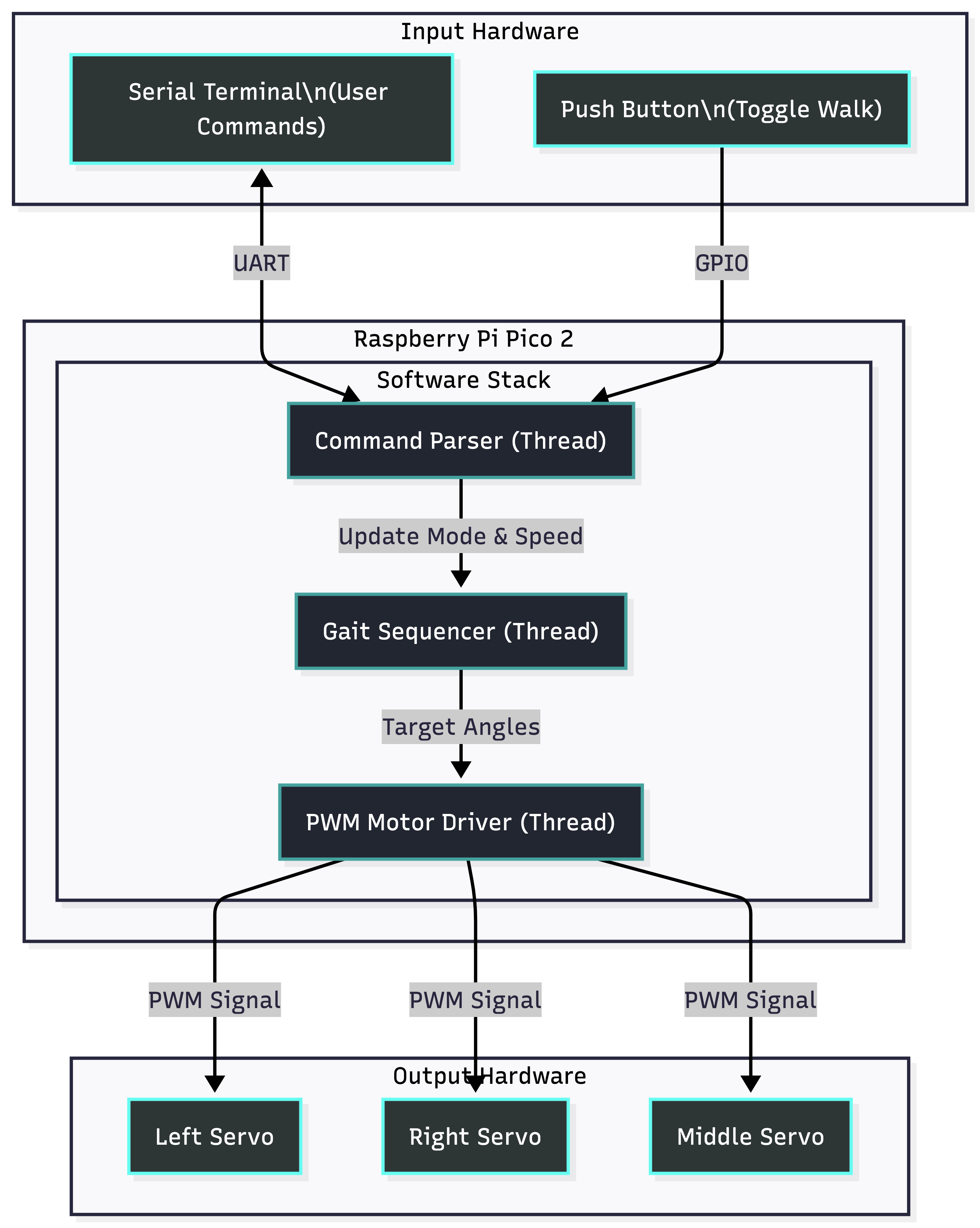
The system is built on the Pico C SDK and utilizes Protothreads for cooperative multitasking. This architecture allows us to handle distinct tasks concurrently without blocking:
- Motor Thread: Handles the precise PWM signaling and smooth angle interpolation for the servos.
- Gait Thread: Orchestrates the high-level sequencing of leg movements (Stick-Slip motion).
- Command Thread: Listens for UART input to toggle modes (Walk, Stop, Calibrate).
Hardware/Software Tradeoffs
Servo Control: We chose standard PWM servos for simplicity and cost. However, they lack position feedback, meaning we had to implement "blind" movement sequences and software-based calibration (trim offsets) to ensure the robot walks straight.
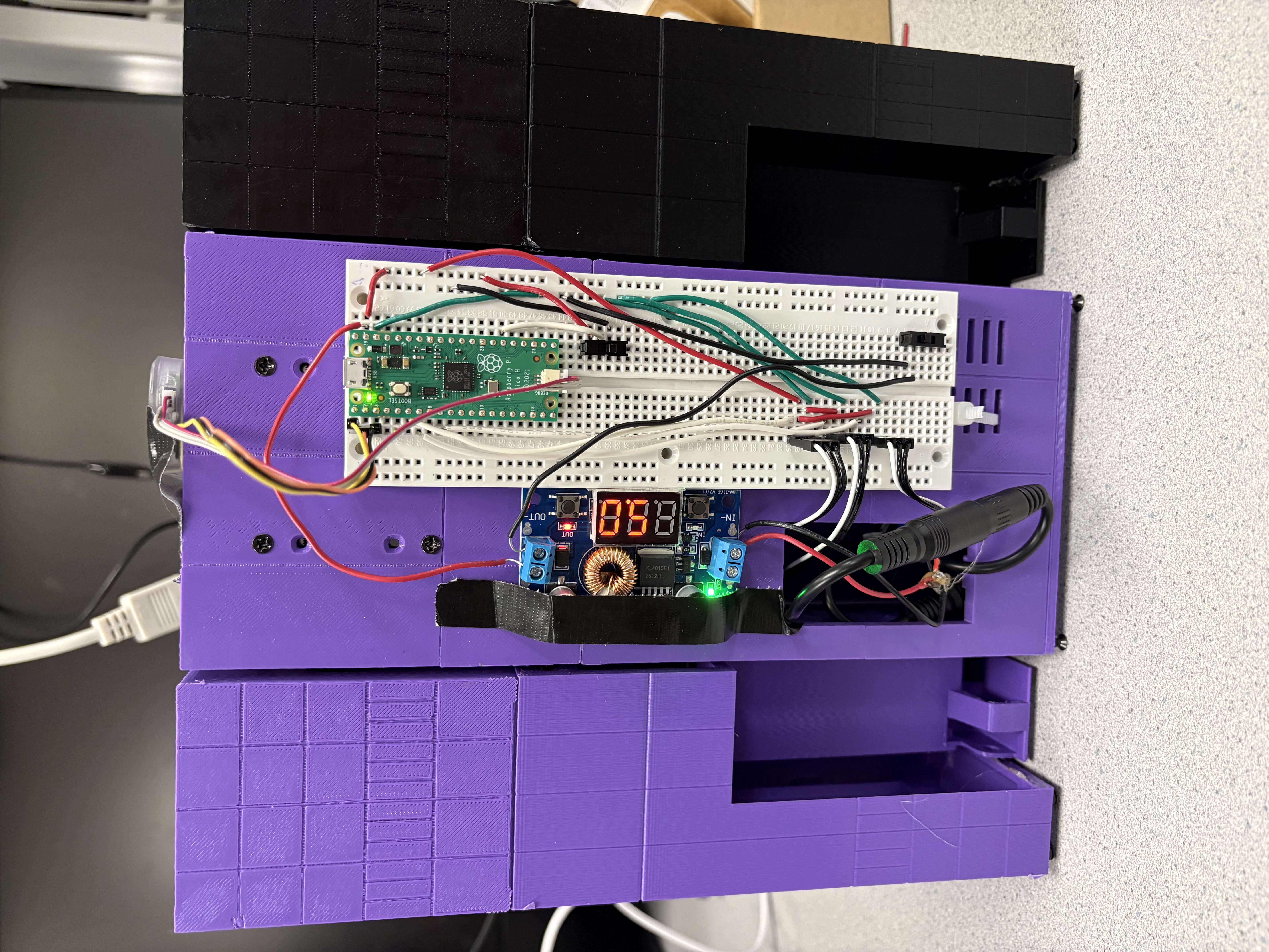
Power: The servos draw significant current under load. We separated the servo power rail (5V external) from the Pico's logic power to prevent brownouts, sharing only a common ground.
3. Program & Hardware Design
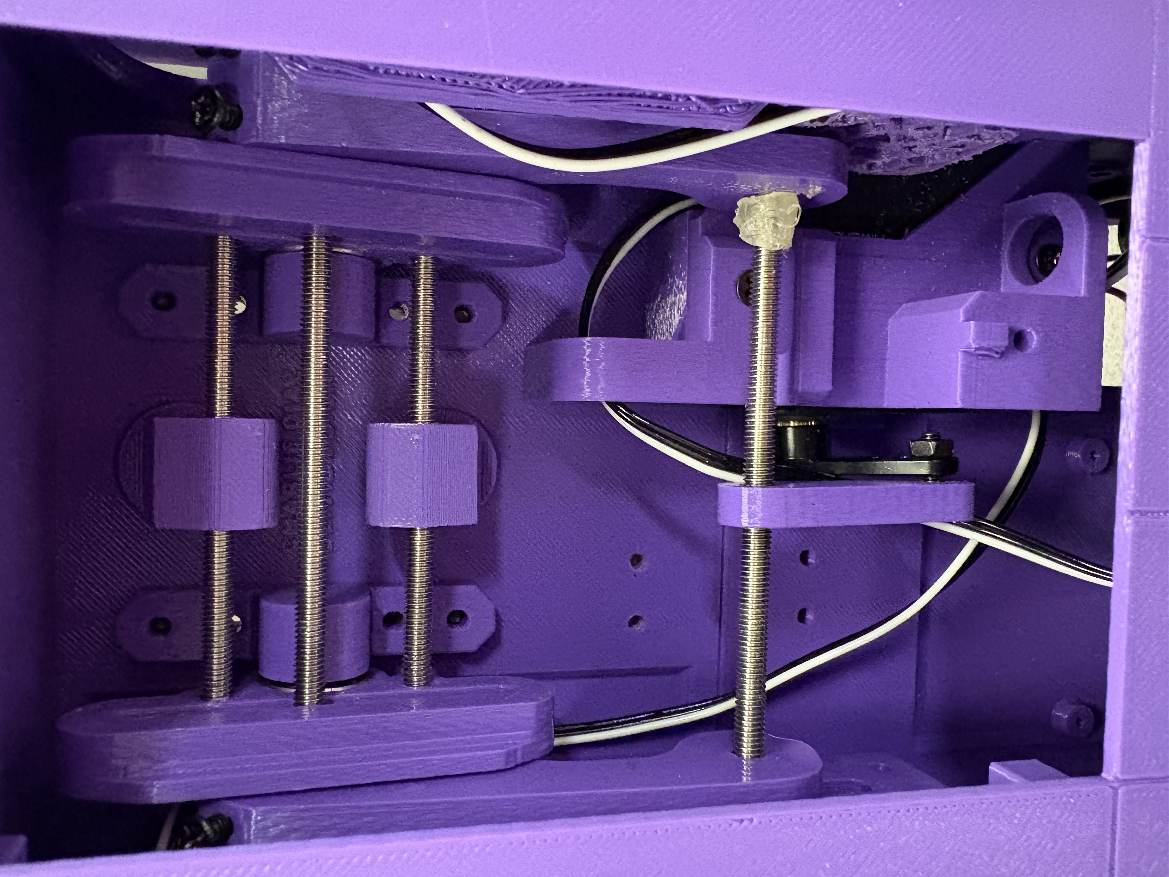
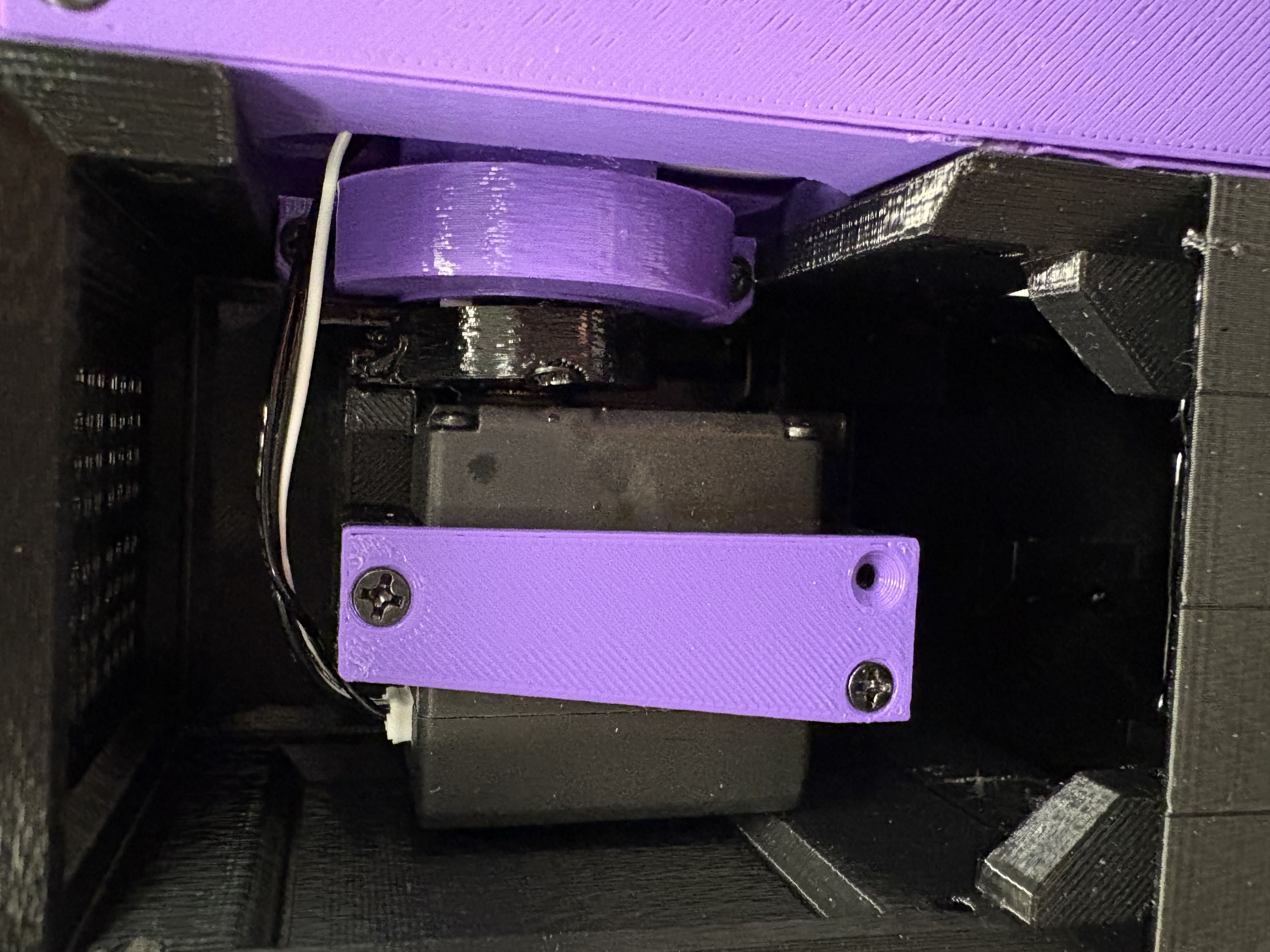
Hardware Details
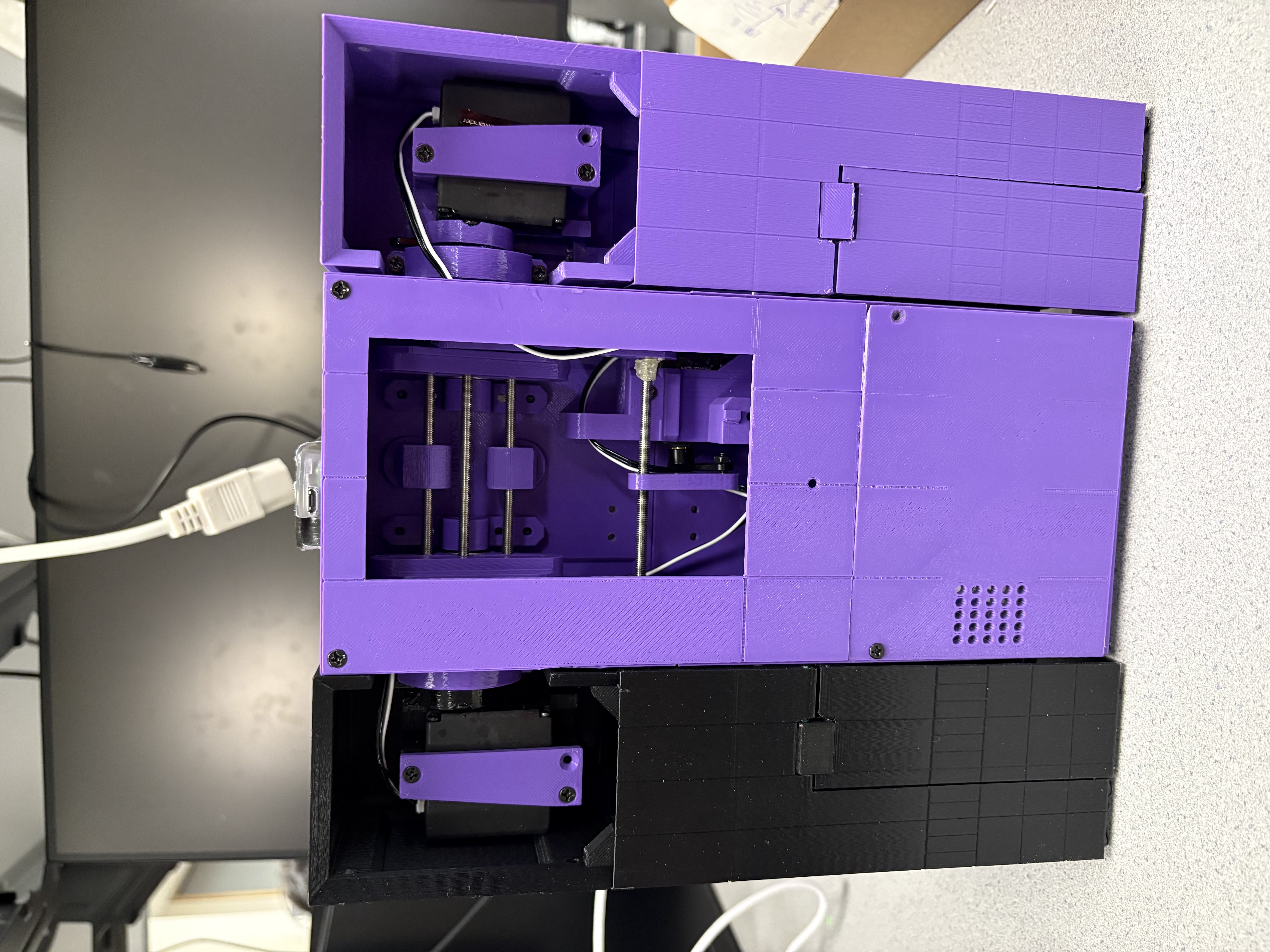
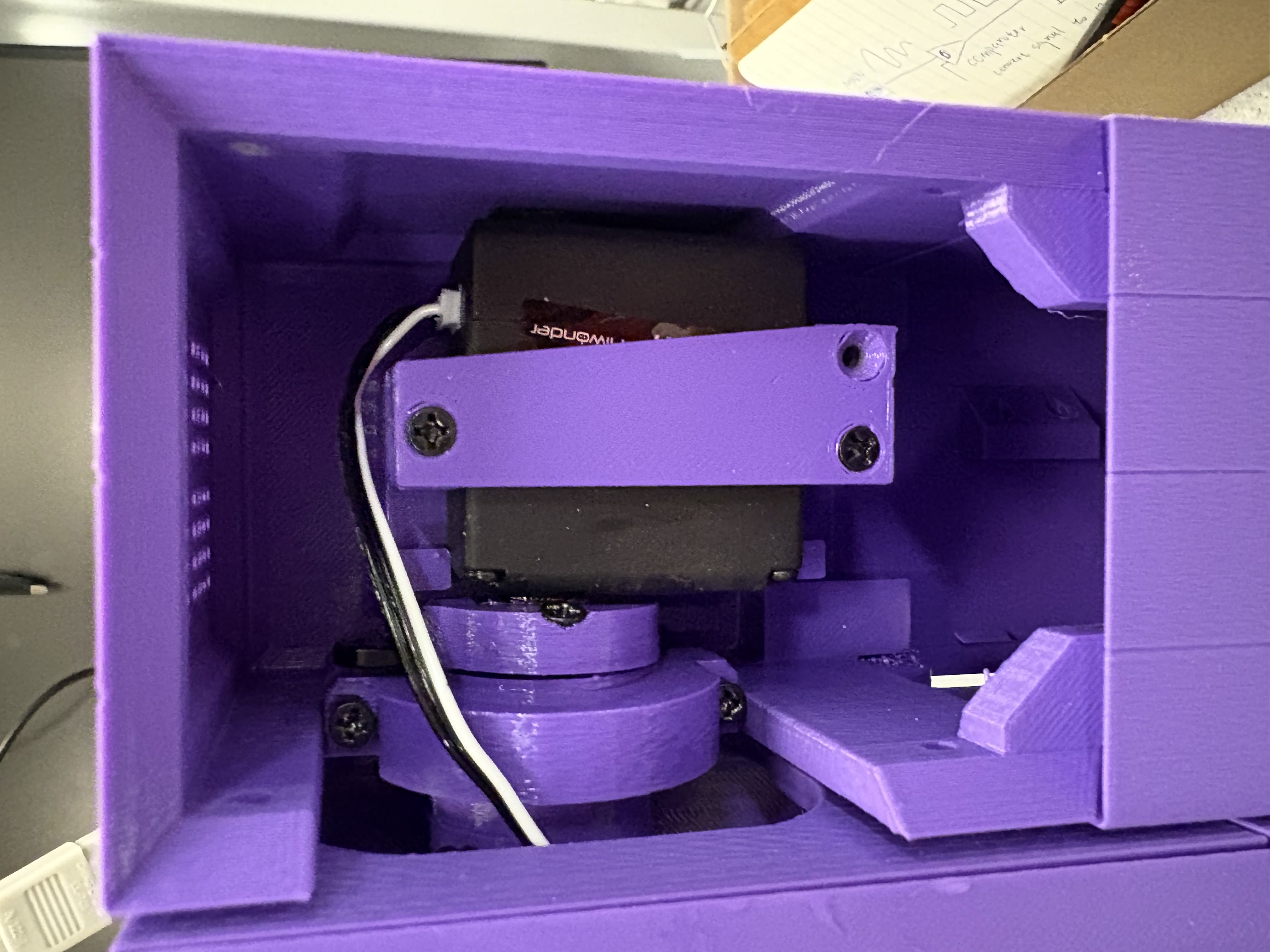
The robot consists of three 3D-printed segments (Legs). The center leg holds the electronics, while the two side legs are actuated to provide forward thrust and balance.
- Microcontroller: Raspberry Pi Pico (RP2040)
- Actuators: 3x MG90S Servos (Left, Right, Middle)
- Power: 7.4V Li-Po Battery regulated to 5V for servos
- Interface: Serial over USB / Button Input
Weight Distribution: Achieving the correct weight distribution was a significant challenge. Since the battery is relatively heavy compared to other components, its placement is crucial. After trial and error, we positioned the battery at the very bottom of the body. This lowers the center of gravity, increasing stability. Additionally, this placement provides more angular momentum when the body swings forward. We also added extra weight around the battery (using magnets) to further enhance stability.
(Hardware connections described in README: GPIO 4, 5, 6 for Servos)
Software Implementation
The core logic is implemented in C. We used a state machine approach for the walking gait:
- Lift Center: Side legs rotate effectively to lift the middle body.
- Swing: The body swings forward relative to the planted legs.
- Retract & Reset: The body lowers and the legs retract for the next cycle.
Motor Range & Calibration: All three servo motors have a maximum range of 270 degrees, which is far more than required. Exceeding the safe operating angles could damage the mechanical assembly or the motors themselves. Therefore, we implemented strict software limits to constrain the motion within safe bounds.
Additionally, we observed slight angle drifts over time, likely due to mechanical tolerances or motor characteristics. To address this, we implemented a configurable offset system. Each motor has an offset angle that can be adjusted in real-time via the serial terminal, allowing us to calibrate the robot's posture without recompiling the code.
Fine-tuning Challenges: Fine-tuning the motor speed and swing angle for the swing movement proved difficult:
- Motor Speed: If too slow, the body cannot fall forward and remains standing on the legs. If too high, the robot becomes unstable after standing on its body.
- Swing Angle: If too small, the body cannot move forward. If too large, the center of gravity shifts too far back when the robot stands on its body, causing it to tip backwards.
System Architecture

4. Results
Performance
The robot successfully demonstrates a walking gait. The movement is smooth due to our incremental servo update logic.
- Speed: Adjustable via serial command. Basic walking speed is approximately 3 seconds per cycle.
- Stability: The robot maintains balance during the swing phase on flat surfaces.
Video Demo
Demo of the walking gait.
Effect of Surface Friction
The robot's performance varies significantly with surface friction. In the demo video above, the robot is placed on a table with lower friction. This allows the robot to slide forward slightly when the body swings forward and catches itself, aiding the movement.
However, when placed on the ground, the higher friction prevents this forward slide. Instead, the momentum causes the robot to wobble back and forth when the body swings forward and catches itself.
Failure Case: Wobbling on high-friction surface.
Solution: To mitigate this, we adjusted the swing angle so that the legs can better support the body and prevent it from tipping backwards. We also added a time delay after the body swings forward, waiting for the body to stabilize before retracting the legs.
5. Conclusions
We successfully built a miniature functional replica of TARS that can walk using a custom RP2040 control backend. The results met our core expectation of replicating the unique "block walking" motion.
Limitations: However, we observed that this specific walking gait is inherently inefficient and unstable. The open-loop nature of the control system makes it highly sensitive to environmental variables, particularly surface friction. Without active feedback, the robot cannot adapt to slips or uneven terrain, making the locomotion unreliable outside of controlled conditions.
Future Work: If we were to do this again, we would incorporate encoders or IMU feedback to enable self-balancing and closed-loop control, as the current open-loop gait is sensitive to surface friction and slight weight imbalances.
Appendices
Appendix A: Permissions
The group approves this report for inclusion on the course website.
The group approves the video for inclusion on the course youtube channel.
Appendix B: Program Listings
Code is available on our GitHub repository: GitHub Link
Appendix C: Task Distribution
- Neil Chou: 3D printing, Mechanical Assembly, Gait Logic (C Implementation).
- Thomas Lin: Circuit Design, PWM Driver Setup, Serial Interface.
References
- TARS-AI Community GitHub - Inspiration for mechanical design.
- Raspberry Pi Pico C/C++ SDK Documentation.