Final Report
Project Introduction
Project Sound Bite
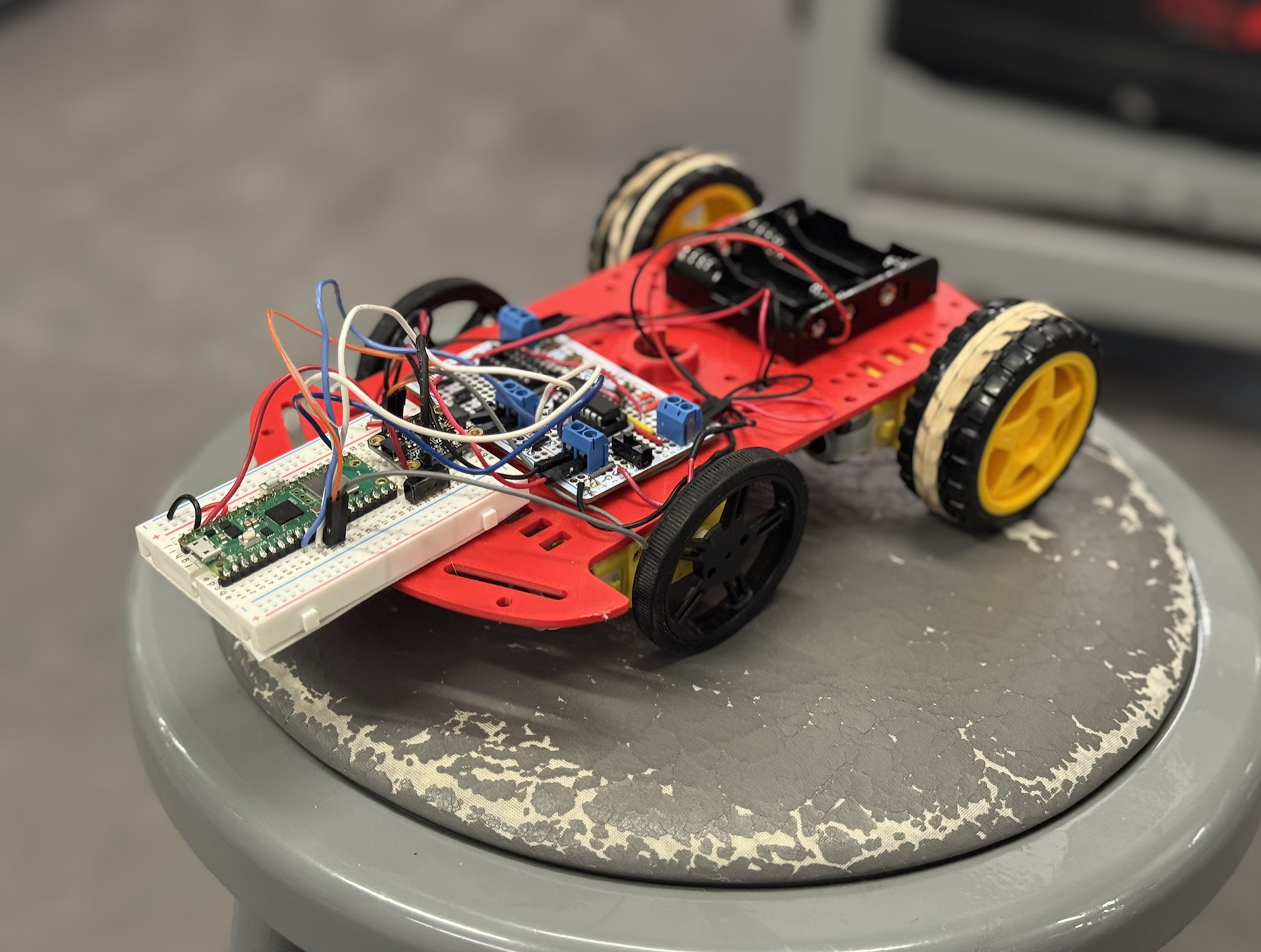 Figure: Autonomous drawing car
Summary
What we did:
We built an autonomous drawing system using two Raspberry Pi Pico Ws that communicate over UDP. One Pico W interfaces with a PC, handling mouse input and VGA output to generate and display waypoints. These waypoints are transmitted wirelessly to a second Pico W mounted on a car. The car uses a 9-axis IMU to determine its orientation, computes PWM values, and drives its motors to reach each target point. The system supports two operating modes. In direct-follow mode, the car traces the path exactly as drawn. In optimized-route mode, the car calculates the shortest path through all points, improving efficiency while preserving the overall flow.
Why we did it:
One group member admired a previous year's drawing robot, and we share an interest in cars and Formula One. All group members work on a student project team that builds autonomous air systems, which motivated us to explore similar concepts on the ground. We wanted to combine creative expression with autonomous vehicle concepts like navigation, state estimation, and control. The project required us to work through autonomous navigation, reliable wireless communication, and real-time control while building something engaging to watch and satisfying to tune.
High Level Design
Rationale and Sources
Our drawing and communication subsystems are based on reference designs and sample code from ECE 4760 course materials provided by Professors Bruce Land and Van Hunter Adams. For the drawing interface, we adapted Professor Land's USB Host HID and VGA graphics demonstrations for the Raspberry Pi Pico RP2040. These examples showed how to run USB mouse input, VGA output, and protothreads concurrently across both cores. We modified this structure to sample mouse position data, generate waypoints, and render the drawing in real time on a VGA display.
The VGA graphics framework and USB HID handling provided a stable foundation. The separation of USB tasks, VGA graphics, and event-handling logic informed our thread organization. We modified the example code to stream drawing coordinates rather than perform direct on-screen drawing, allowing the generated data to be reused as motion commands for the car.
For wireless communication between the two Pico Ws, we based our design on Professor Land's UDP data transfer examples using LWIP and protothreads. These examples demonstrated efficient, low-latency communication between Pico Ws on the same network. We adapted this approach to continuously transmit waypoint data from the PC-side Pico W to the car.
We also used reference material and sample code from Professor Hunter Adams. PWM generation for motor control was adapted from course examples demonstrating the RP2040's hardware PWM peripherals. Sensor interfacing and I2C communication patterns were informed by Professor Adams' sample code, which we extended to support our onboard sensors.
For orientation sensing, we combined these course references with an external driver for the BNO055 9-axis IMU. We adapted the BNO055 driver from the JRDPropulsion BNO055-RP2040-Library (https://github.com/JRDPropulsion/BNO055-RP2040-Library/blob/main/src/BNO055.cpp), converting it from C++ to C for use with the Pico SDK. The driver handled low-level device configuration and data acquisition, allowing us to focus on heading estimation and motor control rather than register-level setup.
Building on established course examples from both professors let us avoid reimplementing low-level drivers and focus on system integration, control logic, and overall behavior.
Background Math
Mathematical Background: Baseline Navigation
This section describes the mathematical model used for baseline robot navigation through a sequence of user-defined waypoints. The approach combines planar geometry, trigonometry, and simple threshold-based control to guide a differential-drive robot along straight-line segments between waypoints.
Coordinate System and Robot Pose
The robot operates in a two-dimensional Cartesian world frame. Its pose is represented as \[ \mathbf{p} = (x, y, \theta), \] where \(x\) and \(y\) denote the robot's position and \(\theta\) is the robot's heading angle in radians, with \(\theta = 0\) aligned with the positive \(x\)-axis. Each waypoint is defined as a fixed target position \[ \mathbf{w}_i = (x_i, y_i). \]
Distance to a Waypoint
The straight-line distance from the robot to a target waypoint is computed using the Euclidean distance formula: \[ d = \sqrt{(x_i - x)^2 + (y_i - y)^2}. \] This distance determines how long the robot drives forward after aligning its heading with the waypoint.
Angle to a Waypoint
The absolute direction from the robot to a waypoint in the world frame is computed using the two-argument arctangent function: \[ \theta_{\text{target}} = \operatorname{atan2}(y_i - y,\; x_i - x). \] The use of \(\operatorname{atan2}\) ensures correct angle computation across all quadrants and avoids division-by-zero errors.
IMU Heading and Degree-to-Radian Conversion
The robot’s heading is measured by an onboard IMU as a yaw angle in degrees. For use in trigonometric calculations, this value is converted to radians: \[ \theta = \theta_{\deg} \cdot \frac{\pi}{180}. \] Using radians ensures compatibility with standard math library functions.
Heading Error and Angle Normalization
The signed heading error between the robot’s current orientation and the desired waypoint direction is given by \[ e_\theta = \theta_{\text{target}} - \theta. \] Because angular quantities are periodic, this error is normalized to the interval \([-\pi, \pi]\) to ensure the robot always turns along the shortest angular path: \[ e_\theta \leftarrow \begin{cases} e_\theta - 2\pi, & e_\theta \ge \pi,\\ e_\theta + 2\pi, & e_\theta < -\pi,\\ e_\theta, & \text{otherwise}. \end{cases} \]
Angular Tolerance and Alignment
Perfect alignment is unnecessary and can cause oscillatory behavior. Instead, the robot is considered aligned when \[ |e_\theta| < \theta_{\text{tol}}, \] where \(\theta_{\text{tol}}\) is a predefined angular tolerance. This threshold improves robustness and reduces control chatter.
Differential-Drive Turning Logic
The robot uses differential drive to rotate in place by driving the left and right motors in opposite directions. The sign of the heading error determines the direction of rotation: \[ \begin{cases} e_\theta > 0 \;\Rightarrow\; \text{turn right},\\ e_\theta < 0 \;\Rightarrow\; \text{turn left}. \end{cases} \] A constant-magnitude PWM signal is applied during turning, resulting in a bang-bang control strategy.
Distance-to-Time Conversion for Forward Motion
Once aligned, the robot drives forward for a duration proportional to the computed distance. Assuming a constant linear speed \(v\), the required travel time is \[ t = \frac{d}{v}. \] This time is converted into milliseconds or microseconds for implementation. The approach is open-loop, meaning the robot does not continuously measure distance during motion.
PWM Scaling and Saturation
Motor commands are implemented using pulse-width modulation (PWM). Commands are constrained to hardware-safe limits: \[ 0 \le \mathrm{PWM} \le \mathrm{PWM}_{\max}. \] A signed PWM convention encodes both direction and magnitude, ensuring safe and consistent motor control.
Baseline Navigation Assumptions
The baseline navigation model assumes:
- Motion occurs on a flat 2D plane.
- IMU heading measurements are sufficiently accurate.
- Forward speed is approximately constant at a fixed PWM level.
- Wheel slip and external disturbances are minimal.
Mathematical Background: Optimized Path Planning
In addition to baseline waypoint following, an optional path optimization step is implemented to reduce total travel distance. This optimization operates on the set of waypoints before transmission to the robot and is independent of the low-level motion controller.
Problem Formulation
Given a starting position \(\mathbf{s}\) and a set of \(N\) waypoints \[ \{\mathbf{w}_1, \mathbf{w}_2, \dots, \mathbf{w}_N\}, \] the objective is to determine an ordering of the waypoints that minimizes the total path length \[ L = \sum_{k=0}^{N-1} \left\lVert \mathbf{p}_{k+1} - \mathbf{p}_k \right\rVert, \] where \(\mathbf{p}_0 = \mathbf{s}\) and \(\mathbf{p}_{k}\) denotes the \(k\)-th waypoint in the chosen route. This problem is a variant of the Traveling Salesman Problem (TSP), which is NP-hard.
Nearest-Neighbor Heuristic
To construct an initial feasible route efficiently, a nearest-neighbor heuristic is used. Starting from the current position \(\mathbf{s}\), the algorithm repeatedly selects the closest unvisited waypoint: \[ \mathbf{w}_{\text{next}} = \arg\min_{\mathbf{w}_i \in \mathcal{U}} \left\lVert \mathbf{w}_i - \mathbf{p}_{\text{current}} \right\rVert, \] where \(\mathcal{U}\) is the set of unvisited waypoints. This approach produces a valid route with low computational cost, though it is not guaranteed to be globally optimal.
2-Opt Local Improvement
To further reduce total path length, the route produced by the nearest-neighbor heuristic is refined using a 2-opt local optimization method. Two edges in the route, \[ (A \rightarrow B) \quad \text{and} \quad (C \rightarrow D), \] are replaced with \[ (A \rightarrow C) \quad \text{and} \quad (B \rightarrow D), \] if doing so reduces the total distance: \[ \lVert A - C \rVert + \lVert B - D \rVert < \lVert A - B \rVert + \lVert C - D \rVert. \] When such an improvement is found, the intermediate segment of the route is reversed. This process is repeated until no further improvements are possible, yielding a locally optimized path.
Optimized Path Characteristics
The optimized route typically results in:
- Reduced total travel distance
- Fewer large heading changes
- Smoother overall trajectories
Although the optimized path is not guaranteed to be globally optimal, the combination of nearest-neighbor initialization and 2-opt refinement provides a strong balance between computational efficiency and path quality for real-time use.
Integration with Navigation Controller
Once computed, the optimized waypoint order is transmitted to the robot in the same format as the baseline route. The low-level navigation controller operates identically in both cases, ensuring modular separation between high-level path planning and low-level motion control.
Logical Structure
The system architecture uses two cooperating Pico W subsystems. The PC-side Pico W reads mouse input via USB HID, maintains a VGA display of the drawing interface, generates waypoints, and sends them via UDP. The car-side Pico W receives UDP waypoints and queues them for execution, reads BNO055 Euler angles for heading estimation, computes heading error and distance to the next waypoint, executes motor control through PWM signals, and runs a PWM ISR for precise motor timing without blocking main control loops.
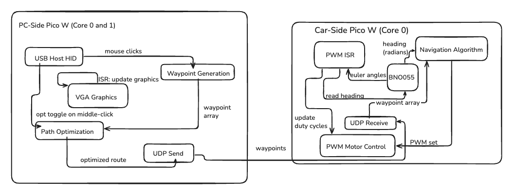 Figure: System architecture diagram showing the PC-side and car-side Pico W subsystems, their internal components, and data flow between them.
Hardware/Software Tradeoffs
Hardware
Chassis and Marker Mounting
The car uses a reverse-engineered chassis with a centrally mounted hole to hold a dry erase marker. This design is simple to CAD and ensures rigidity, reducing wobble during movement. However, accurately positioning the marker at the optimal height is challenging. If the marker sits too low, it drags against the surface and resists motion, introducing extra friction. If it's too high, the drawn line may be faint or inconsistent. Misalignment can also alter the car's motion, reducing path accuracy, especially during sharp turns or tight curves. The tradeoff is between ease of construction and mechanical precision: a simple rigid mount is easier to fabricate, but fine-tuning marker height and placement is time-consuming and directly affects performance.
Software
Motor Control
The car has no wheel encoders, so position is estimated by sequentially updating the pose at each waypoint and correcting heading using the BNO055 IMU. We chose to forgo encoders because we were satisfied with timing-based control, where the duration of the "drive forward" command is calculated based on distance and expected speed. This approach reduces hardware complexity and simplifies the control system. However, this timing-based method assumes consistent motor performance and surface conditions. In cases where there is increased friction, such as when the marker is positioned too low and drags against the drawing surface, the car travels a shorter distance than expected for the given time duration. This causes position estimation errors and cumulative drift, particularly over longer paths or during tight turns. The lack of position feedback means the system cannot detect or compensate for these variations in actual distance traveled. PWM duty cycles are tuned to balance speed and stability under normal conditions. High duty cycles can saturate the motors, causing uneven motion or overshoot, while too low duty cycles reduce responsiveness. The control loop continuously adjusts left/right motor speeds based on heading error, ensuring the car corrects deviations dynamically, but it cannot correct for distance errors without encoder feedback.
Communication
UDP was chosen for its low-latency characteristics, ideal for real-time transmission of waypoints from the PC-side Pico W. UDP operates on a "quantity over quality" principle, where packets may be lost and there is no way to verify on the PC-side (sender) that the data was received by the car (receiver). We contemplated switching to TCP or Bluetooth after noticing lags and pairing issues, but later realized that the problems were caused by the RedRover connection, not UDP itself. After switching to a phone hotspot, UDP proved to be quite reliable. There is a tradeoff with UDP: without any feedback or acknowledgment from the receiver, we don't have full interactivity. To allow the user to append more waypoints to the car, we leave it up to the user to wait for the car to finish its previous course. When sending a new payload, the sender updates the first element of the data array, which indicates how many total waypoints are encoded. The car receives this value and compares it to the previous count. When the car receives a value in the first element that is greater than the previous count, it knows the data is newly received and where to begin reading new waypoints. Dropped packets are tolerated; continuous streaming ensures that missing points have minimal effect on overall path execution.
IMU Integration
The BNO055 provides Euler angles for heading estimation, allowing the car to maintain a correct trajectory toward each waypoint. While the driver simplifies access to orientation data, it limits low-level timing control, which can slightly reduce precision when combined with PWM motor updates. IMU readings are polled at high frequency and integrated with motor commands to allow real-time heading correction.
Software Architecture
Two Pico Ws separate concerns: the PC-side handles USB mouse input, waypoint generation, and VGA visualization, while the car-side manages sensing, control logic, and motor actuation. This separation reduces timing conflicts and ensures that heavy computation on one side (e.g., VGA rendering) does not disrupt motor control or heading updates. Protothreads enable cooperative multitasking, efficiently scheduling multiple tasks without preemption overhead. Tasks include UDP packet reception, IMU reading, heading computation, motor PWM updates, and optional VGA debug output. Careful thread synchronization is required, especially for tasks tied to PWM timing and real-time UDP handling. The ISR-driven motor PWM ensures precise motor timing independent of the main control loop, while cooperative threads manage higher-level decision-making.
Software Design
The software architecture is divided into two subsystems running on separate Pico Ws: the PC-side interface and the car-side control system. Both systems use protothreads for cooperative multitasking, enabling concurrent execution of multiple tasks without preemption overhead.
1. PC-Side Software
The PC-side Pico W runs on dual cores with the following thread organization:
- Core 0: UDP communication, USB HID processing, waypoint management, LED status
- Core 1: VGA graphics rendering (dedicated core for display updates)
1.1 VGA Graphics Subsystem
The VGA display runs on Core 1 using the VGA16 graphics library, providing a 640×480 pixel, 16-color display. The VGA thread continuously updates the screen to show the drawing interface, waypoint markers, and system status at approximately 60 Hz.
/**
 * VGA graphics thread (Core 1)
 * Continuously renders the drawing interface, waypoints, and status information
 * Updates at ~60 Hz for smooth display
 */
PT_THREAD (protothread_vga(struct pt *pt))
{
    PT_BEGIN(pt);
    static char video_str[64], mouse_str[10];
    static unsigned char draw_color = GREEN;
    static int prev_dot_x = -1, prev_dot_y = -1;
    static int has_prev_dot = 0;

    // Display team names and status information
    setTextColor(WHITE);
    setCursor(65, 20);
    writeString("Sarah Zhong");
    // ... additional team member names

    while (1) {
        // Get current mouse position and waypoint count
        extern int mouse_x, mouse_y, mouse_button;
        extern short data_array[];
        int waypoint_count = (data_array[0] >= 0) ? (int)data_array[0] : 0;

        // Draw cursor at mouse position
        erase_cursor(prev_cursor_x, prev_cursor_y);
        draw_cursor(mouse_x, mouse_y);

        // Draw waypoints and connecting lines
        if (waypoint_count > 0) {
            // Draw waypoint markers and connecting lines
            for (int i = 0; i < waypoint_count; i++) {
                int base = 3 + i * 2;
                int wp_x = data_array[base];
                int wp_y = data_array[base + 1];
                fillCircle(wp_x, wp_y, 3, draw_color);
                // Draw line to previous waypoint
                if (i > 0) {
                    int prev_base = 3 + (i - 1) * 2;
                    drawLine(data_array[prev_base], data_array[prev_base + 1],
                              wp_x, wp_y, draw_color);
                }
            }
        }

        // Update status text (waypoint count, UDP status, optimization mode)
        sprintf(video_str, "Waypoints: %d", waypoint_count);
        setCursor(505, 30);
        writeString(video_str);

        PT_YIELD_usec(16667);  // ~60 Hz update rate
    }
    PT_END(pt);
}
The VGA subsystem uses a framebuffer approach where pixel data is stored in a 153.6 kB array (`vga_data_array`). Each byte encodes two pixels (4 bits per pixel for 16 colors). The display is updated via DMA transfers to the VGA connector, with horizontal and vertical sync signals generated by PIO state machines.
1.2 USB Mouse Input Subsystem
Mouse input is handled using TinyUSB's USB Host functionality. The HID thread polls the USB bus at 125 Hz to detect mouse movement and button clicks, updating global variables for mouse position and button state.
/**
 * USB HID thread (Core 0)
 * Polls USB bus for mouse input at 125 Hz
 * Updates global mouse_x, mouse_y, and mouse_button variables
 */
PT_THREAD (protothread_hid(struct pt *pt))
{
    PT_BEGIN(pt);
    while (1) {
        tuh_task();  // Process USB host events
        PT_YIELD_usec(8000);  // 125 Hz polling rate
    }
    PT_END(pt);
}
Mouse coordinates are captured in the `my_hid_app.c` callback functions, which update global variables `mouse_x`, `mouse_y`, and `mouse_button`. The mouse position is constrained to the VGA display bounds (0-639 for x, 0-479 for y).
1.3 Waypoint Generation and Management
Waypoints are captured when the user left-clicks on the VGA display. The mouse sender thread monitors button state changes using edge detection and adds waypoints to the data array.
/**
 * Mouse sender thread (Core 0)
 * Monitors mouse clicks and manages waypoint capture/sending
 * Handles auto-pairing, waypoint accumulation, and UDP transmission
 */
static PT_THREAD (protothread_mouse_sender(struct pt *pt))
{
    PT_BEGIN(pt);
    extern int mouse_x, mouse_y, mouse_button;
    static int prev_mouse_button = 0;
    static int pairing_sent = 0, ack_sent = 0;

    while (1) {
        // Step 1: Auto-pairing - send IP address until paired
        if (!paired) {
            memset(send_data, 0, UDP_MSG_LEN_MAX);
            sprintf(send_data, "IP %s",
                     ip4addr_ntoa(netif_ip4_addr(netif_list)));
            packet_length = command;
            PT_SEM_SIGNAL(pt, &new_udp_send_s);
            PT_YIELD_INTERVAL(1000000);  // Retry every 1 second
        }

        // Step 2: Left-click detection - add waypoint
        if (paired && ack_sent && (mouse_button & 1) && !(prev_mouse_button & 1)) {
            // Edge detection: button just pressed
            if (click_count == 0) {
                reset_data_array();
                // First waypoint: set robot position
                data_array[1] = mouse_x;  // robot x
                data_array[2] = mouse_y;  // robot y
                data_array[3] = mouse_x;  // waypoint1 x
                data_array[4] = mouse_y;  // waypoint1 y
            } else {
                // Subsequent waypoints: append to array
                int base = 3 + click_count * 2;
                if (base + 1 < MAX_DATA_SIZE) {
                    data_array[base] = mouse_x;
                    data_array[base + 1] = mouse_y;
                }
            }
            click_count++;
            data_array[0] = (short)click_count;  // Update waypoint count
            optimized_route_valid = 0;  // Invalidate optimized route
        }

        // Step 3: Right-click detection - send waypoints to car
        if (paired && ack_sent && (mouse_button & 2) && !(prev_mouse_button & 2)) {
            if (click_count > 0) {
                short *route_ptr = data_array;

                // Apply path optimization if enabled
                if (use_optimized_route) {
                    if (!optimized_route_valid) {
                        optimized_route_valid = update_optimized_waypoints();
                    }
                    if (optimized_route_valid) {
                        route_ptr = optimized_waypoint_array;
                    }
                }

                // Copy route to send buffer and transmit
                memcpy(send_data, route_ptr, send_data_size);
                packet_length = data;
                PT_SEM_SIGNAL(pt, &new_udp_send_s);
                continuously_sending = 1;
            }
        }

        prev_mouse_button = mouse_button;
        PT_YIELD_usec(10000);  // 100 Hz polling
    }
    PT_END(pt);
}
Data Array Format: The waypoint data is stored in a `short` array with the following structure:
data_array[0]: Waypoint count (number of waypoints)data_array[1]: Robot starting X positiondata_array[2]: Robot starting Y positiondata_array[3], data_array[4]: Waypoint 1 (x, y)data_array[5], data_array[6]: Waypoint 2 (x, y)- ... and so on for subsequent waypoints
1.4 Path Optimization Subsystem
When optimization mode is enabled, the system applies two algorithms to minimize travel distance: Nearest Neighbor for initial route construction, followed by 2-Opt local improvement. The optimization runs only when the user right-clicks to send waypoints, preventing VGA freezes during waypoint accumulation.
/**
 * Update optimized waypoint order
 * Applies nearest-neighbor and 2-opt algorithms
 * Returns true if optimization succeeded
 */
static bool update_optimized_waypoints(void)
{
    if (!use_optimized_route || click_count <= 0) {
        return false;
    }

    // Extract waypoints to optimize (skip prefix waypoints if needed)
    waypoint_point_t points[MAX_WAYPOINTS];
    int valid_points = 0;
    int prefix_count = optimize_start_waypoint;

    for (int i = 0; i < suffix_count; i++) {
        int base = 3 + (prefix_count + i) * 2;
        points[valid_points].x = (float)data_array[base];
        points[valid_points].y = (float)data_array[base + 1];
        points[valid_points].raw_x = data_array[base];
        points[valid_points].raw_y = data_array[base + 1];
        valid_points++;
    }

    // Build optimized route
    int route[MAX_WAYPOINTS];
    compute_nearest_neighbor_route(points, valid_points, start_point, route);
    two_opt_local_improvement(points, valid_points, start_point, route);

    // Reorder waypoints according to optimized route
    for (int i = 0; i < valid_points; i++) {
        int src_idx = route[i];
        optimized_waypoint_array[dest_index++] = points[src_idx].raw_x;
        optimized_waypoint_array[dest_index++] = points[src_idx].raw_y;
    }

    optimized_route_valid = 1;
    return true;
}
Note: Detailed algorithm explanations and mathematical background are provided in a separate algorithms document.
1.5 UDP Transmission
The UDP send thread waits on a semaphore until waypoint data is ready to transmit. It handles both command packets (pairing, acknowledgments) and data packets (waypoint arrays).
/**
 * UDP send thread (Core 0)
 * Transmits waypoint data or command packets to car-side Pico W
 * Uses semaphore-based signaling for non-blocking operation
 */
static PT_THREAD (protothread_udp_send(struct pt *pt))
{
    PT_BEGIN(pt);
    static struct udp_pcb* pcb = udp_new();
    static ip_addr_t addr;

    while (true) {
        // Wait for data to send (signaled by mouse_sender thread)
        PT_SEM_WAIT(pt, &new_udp_send_s);

        // Determine destination IP (car-side Pico W)
        ipaddr_aton(udp_target_pico, &addr);

        // Determine packet length based on type
        int udp_send_length;
        switch (packet_length) {
            case command: udp_send_length = 32; break;
            case data:     udp_send_length = send_data_size; break;
            case ack:      udp_send_length = 5; break;
        }

        // Allocate packet buffer and copy data
        struct pbuf *p = pbuf_alloc(PBUF_TRANSPORT, udp_send_length + 1, PBUF_RAM);
        memcpy(p->payload, send_data, udp_send_length);

        // Transmit packet
        err_t err = udp_sendto(pcb, p, &addr, UDP_PORT);
        pbuf_free(p);
    }
    PT_END(pt);
}
2. Car-Side Software
The car-side Pico W runs all control logic on Core 0, with Core 1 reserved for future expansion. The system uses a state machine to navigate between waypoints, reading IMU data for heading estimation.
2.1 Data Structures
/**
 * Robot pose structure
 * Tracks current position and heading in world coordinates
 */
typedef struct {
    float x;              // X position (units, matches VGA coordinates)
    float y;              // Y position (units)
    float heading_rad;    // Current heading angle (radians, 0 = +x axis)
} pose_t;

/**
 * Waypoint structure
 * Stores target coordinates for navigation
 */
typedef struct {
    float x;              // Target X coordinate
    float y;              // Target Y coordinate
} waypoint_t;

// Global robot state
pose_t robot = { .x = 0.0f, .y = 0.0f, .heading_rad = 0.0f };
waypoint_t waypoints[NUM_WAYPOINTS];  // Array of waypoints (max 20)

// Movement constants
#define PWM_FORWARD       5000.0f   // Forward PWM duty cycle
#define TURN_PWM          3500.0f   // Turning PWM duty cycle
#define ANGLE_TOL_RAD     (10.0f * 3.14159265f / 180.0f)  // 10° tolerance
#define UNITS_PER_SECOND  200.0f     // Robot speed: 200 units/second
2.2 UDP Reception and Waypoint Parsing
The car-side UDP receive callback runs in an interrupt context when packets arrive. It copies the packet payload to a receive buffer and signals the receive thread via semaphore.
/**
 * UDP receive callback (ISR context)
 * Called by lwIP when UDP packet arrives
 * MUST be kept short - only copies data and signals thread
 */
static void udpecho_raw_recv(void *arg, struct udp_pcb *upcb,
                                 struct pbuf *p, const ip_addr_t *addr, u16_t port)
{
    if (p != NULL) {
        // Copy packet payload to receive buffer
        memcpy(recv_data, p->payload, UDP_MSG_LEN_MAX);

        // Signal receive thread (safe to call from ISR)
        PT_SEM_SIGNAL(pt, &new_udp_recv_s);

        pbuf_free(p);  // Free packet buffer
    }
}

/**
 * UDP receive processing thread
 * Parses received waypoint data and updates waypoint array
 */
static PT_THREAD (protothread_udp_recv(struct pt *pt))
{
    PT_BEGIN(pt);
    while (1) {
        // Wait for new packet (signaled by ISR)
        PT_SEM_WAIT(pt, &new_udp_recv_s);

        // Copy binary waypoint data to data_array
        memcpy(data_array, recv_data, send_data_size);

        // Send acknowledgment back to PC-side
        memset(send_data, 0, UDP_MSG_LEN_MAX);
        sprintf(send_data, "ack");
        packet_length = ack;
        PT_SEM_SIGNAL(pt, &new_udp_send_s);
    }
    PT_END(pt);
}
2.3 IMU Integration
The BNO055 IMU is read via I2C. Heading data is read in the PWM interrupt service routine to ensure high-frequency updates without blocking the main control loop.
/**
 * PWM wrap interrupt service routine
 * Called periodically by hardware PWM timer
 * Reads IMU Euler angles for heading estimation
 * Runs at PWM frequency (~1 kHz for motors)
 */
void on_pwm_wrap() {
    // Clear interrupt flags
    pwm_clear_irq(slice_fwd);
    pwm_clear_irq(slice_rev);

    // Read BNO055 Euler angles (yaw/pitch/roll)
    // Data is in 15.16 fixed-point format
    // euler[0] = yaw (heading) in degrees
    bno055_read_euler(euler);
}

/**
 * Update robot heading from IMU
 * Converts fixed-point degrees to radians
 */
static void update_robot_heading_from_imu(void)
{
    float yaw_deg = fix2float15(euler[0]);   // Convert 15.16 fixed-point to float
    robot.heading_rad = deg2rad(yaw_deg);    // Store in radians
}
The BNO055 is configured in NDOF (Nine Degrees of Freedom) fusion mode, which internally combines accelerometer, gyroscope, and magnetometer data to provide stable Euler angles. The I2C communication runs at 400 kHz, and the sensor is polled at approximately 1 kHz via the PWM ISR.
2.4 Motor Control Functions
Motor control uses the RP2040's hardware PWM peripherals. Four PWM channels control the H-bridge driver: two for forward motion (GPIO16, GPIO17) and two for reverse (GPIO6, GPIO7). Motors use a wrap value of 5000 with a clock divider of 25.0, resulting in a PWM frequency of approximately 1 kHz.
/**
 * Set left motor speed with signed value
 * Positive = forward, negative = backward, zero = stop
 * Uses separate PWM slices for forward and reverse channels
 */
void set_left_motor_signed(float speed) {
    if (speed > 0.0f) {
        // Forward: use forward PWM channel (GPIO16)
        left_forward_pin_pwm(speed);
        left_reverse_pin_pwm(0.0f);
    } else if (speed < 0.0f) {
        // Backward: use reverse PWM channel (GPIO7)
        left_forward_pin_pwm(0.0f);
        left_reverse_pin_pwm(-speed);  // Negate to get positive PWM value
    } else {
        // Stop: set both channels to zero
        left_forward_pin_pwm(0.0f);
        left_reverse_pin_pwm(0.0f);
    }
}

/**
 * Low-level PWM helper with clamping
 * Ensures duty cycle stays within valid range [0, WRAPVAL]
 */
static inline void left_forward_pin_pwm(float pwm) {
    if (pwm < 0.0f) pwm = 0.0f;
    if (pwm > (float)WRAPVAL) pwm = (float)WRAPVAL;
    pwm_set_chan_level(slice_fwd, PWM_CHAN_A, pwm);  // GPIO16
}
2.5 Navigation State Machine
The main control loop implements a three-state finite state machine for waypoint navigation.
/**
 * Main movement control thread
 * Implements state machine: WAITING → TURNING → DRIVING → TURNING → ...
 * Handles dynamic waypoint addition during execution
 */
static PT_THREAD (protothread_I_like_to_move_it_move_it(struct pt *pt))
{
    PT_BEGIN(pt);
    static enum {
        MOVE_WAITING_FOR_ROUTE = 0,
        MOVE_TURNING,
        MOVE_DRIVING
    } move_state = MOVE_WAITING_FOR_ROUTE;
    static uint64_t drive_end_time_us = 0;
    static waypoint_t *current_target = NULL;
    static int last_seen_waypoint_count = -1;

    while (1) {
        uint32_t delay_us = 50000;  // 50ms default (20 Hz control loop)

        // Check for new waypoint data
        if (data_array[0] != -1 && data_array[0] > last_seen_waypoint_count) {
            int current_waypoint_count = data_array[0];

            if (!route_initialized) {
                // First time: initialize robot position and load all waypoints
                populate_robot();
                populate_waypoints_from_index(0);
                current_waypoint = 1;  // Start from waypoint 1 (skip waypoint 0 = home)
                route_initialized = true;
                move_state = MOVE_TURNING;
            } else {
                // More waypoints added: load only new waypoints, keep current position
                int start_index = last_processed_waypoint_index + 1;
                populate_waypoints_from_index(start_index);
                current_waypoint = start_index;
                if (current_waypoint < loaded_waypoint_count) {
                    move_state = MOVE_TURNING;  // Resume navigation
                }
            }
            last_seen_waypoint_count = current_waypoint_count;
        }

        // State machine execution
        switch (move_state) {
            case MOVE_WAITING_FOR_ROUTE:
                delay_us = 200000;  // Wait 200ms when no route
                break;

            case MOVE_TURNING: {
                update_robot_heading_from_imu();
                float err = turn_angle_to_waypoint(&robot, current_target);

                if (fabsf(err) < ANGLE_TOL_RAD) {
                    // Aligned: check distance and transition to driving
                    set_left_motor_signed(0.0f);
                    set_right_motor_signed(0.0f);

                    float dist = distance_to_waypoint(&robot, current_target);
                    if (dist < 0.01f) {
                        // Already at waypoint
                        robot.x = current_target->x;
                        robot.y = current_target->y;
                        current_waypoint++;
                        break;
                    }

                    // Calculate drive time and start forward motion
                    float time_s = dist / UNITS_PER_SECOND;
                    drive_end_time_us = time_us_64() + (uint64_t)(time_s * 1000000.0f);
                    set_left_motor_signed(PWM_FORWARD);
                    set_right_motor_signed(PWM_FORWARD);
                    move_state = MOVE_DRIVING;
                } else if (err < 0.0f) {
                    // Turn left: differential steering
                    set_left_motor_signed(-TURN_PWM);
                    set_right_motor_signed(+TURN_PWM);
                } else {
                    // Turn right
                    set_left_motor_signed(+TURN_PWM);
                    set_right_motor_signed(-TURN_PWM);
                }
                delay_us = 50000;
                break;
            }

            case MOVE_DRIVING: {
                if (time_us_64() >= drive_end_time_us) {
                    // Time-based motion complete
                    set_left_motor_signed(0.0f);
                    set_right_motor_signed(0.0f);
                    robot.x = current_target->x;  // Update position
                    robot.y = current_target->y;
                    current_waypoint++;
                    move_state = MOVE_TURNING;  // Transition back to turning
                } else {
                    // Continue driving forward
                    set_left_motor_signed(PWM_FORWARD);
                    set_right_motor_signed(PWM_FORWARD);
                }
                delay_us = 50000;
                break;
            }
        }

        PT_YIELD_usec(delay_us);
    }
    PT_END(pt);
}
State Transitions:
- MOVE_WAITING_FOR_ROUTE: Initial state when no waypoints are available. Car remains stationary.
- MOVE_TURNING: Car rotates to face the current target waypoint. Uses differential steering (left and right motors run in opposite directions). Exits when heading error is within 10° tolerance.
- MOVE_DRIVING: Car moves forward in a straight line for a calculated duration based on distance and speed. Uses time-based control rather than position feedback (no encoders).
3. Communication Subsystem
3.1 UDP Protocol
Communication between PC-side and car-side Pico Ws uses UDP over Wi-Fi. The protocol supports three packet types. Command packets are 32 bytes, used for pairing ("IP <address>") and acknowledgments ("ack"). Data packets are variable length (up to 1024 bytes) and contain the waypoint array. Acknowledgment packets are 5 bytes and confirm data receipt.
3.2 Pairing Mechanism
The system uses an automatic pairing protocol to discover and connect the two Pico Ws. The PC-side broadcasts its IP address as "IP 192.168.1.100". The car-side receives the broadcast and responds with its own IP as "IP 192.168.1.101". Both sides store each other's IP addresses and mark paired = true. The car-side sends an acknowledgment "ack", and the PC-side begins sending waypoint data.
/**
 * Pairing packet handling in UDP receive thread
 */
if (strcmp(arg1, "IP") == 0) {
    if (mode == echo) {  // Car-side (echo unit)
        // Save sender's IP address
        strcpy(udp_target_pico, arg2);
        paired = true;

        // Respond with our IP address
        memset(send_data, 0, UDP_MSG_LEN_MAX);
        sprintf(send_data, "IP %s",
                 ip4addr_ntoa(netif_ip4_addr(netif_list)));
        packet_length = command;
        PT_SEM_SIGNAL(pt, &new_udp_send_s);
    } else {  // PC-side (send unit)
        // Save car's IP address
        strcpy(udp_target_pico, arg2);
        paired = true;
    }
}
3.3 Packet Format
Waypoint data packets use a binary format for efficiency. Bytes 0-1 contain the waypoint count (short, 2 bytes). Bytes 2-3 contain the robot starting X position (short, 2 bytes). Bytes 4-5 contain the robot starting Y position (short, 2 bytes). Bytes 6 and beyond contain waypoint coordinates as pairs of shorts (x, y, x, y, ...). This binary format minimizes packet size compared to text-based protocols, reducing transmission time and improving real-time responsiveness.
3.4 Thread Synchronization
Inter-thread communication uses protothread semaphores. The new_udp_recv_s semaphore is signaled by the UDP receive ISR when a packet arrives. The new_udp_send_s semaphore is signaled by the mouse sender thread when waypoints are ready to transmit. These semaphores enable non-blocking, event-driven communication between threads, ensuring that heavy VGA rendering or UDP transmission doesn't block mouse input processing or motor control.
3.5 Error Handling and Reliability
UDP is connectionless and doesn't guarantee delivery. The system handles this through several mechanisms. After right-click, waypoint data is sent repeatedly until new waypoints arrive. The car-side sends "ack" packets to confirm receipt, though this is not strictly required for operation. New waypoints can be added while the car is moving, and the car will incorporate them into its path. The waypoint count in data_array[0] allows detection of new waypoint sets.
4. Thread Organization and Concurrency
4.1 PC-Side Threads (Core 0)
Core 0 runs several protothreads. The protothread_udp_recv thread processes incoming UDP packets (pairing, acknowledgments). The protothread_udp_send thread transmits waypoint data and command packets. The protothread_hid thread polls the USB bus for mouse input at 125 Hz. The protothread_mouse_sender thread monitors mouse clicks, manages waypoint accumulation, and triggers UDP transmission. The protothread_toggle_cyw43 thread blinks the Wi-Fi LED to indicate system status.
4.2 PC-Side Threads (Core 1)
Core 1 runs the protothread_vga thread, which renders the VGA display at approximately 60 Hz, drawing waypoints, cursor, and status text.
4.3 Car-Side Threads (Core 0)
Core 0 runs several protothreads. The protothread_udp_recv thread parses received waypoint data and updates data_array. The protothread_udp_send thread sends acknowledgment packets back to the PC-side. The protothread_I_like_to_move_it_move_it thread implements the main navigation control loop with the state machine. The protothread_toggle_cyw43 thread provides status LED indication.
4.4 Interrupt Service Routines
Two interrupt service routines handle time-critical operations. The PWM Wrap ISR updates motor PWM duty cycles and reads IMU data at approximately 1 kHz. The UDP Receive ISR copies incoming packets to a buffer and signals the receive thread (asynchronous, triggered by lwIP). All ISRs are kept minimal to avoid blocking other system operations. The PWM ISR only updates hardware registers and reads sensor data, while the UDP ISR only copies data and signals a semaphore.
Hardware Details
Electrical Hardware
 Figure: Electronics mounted on the car
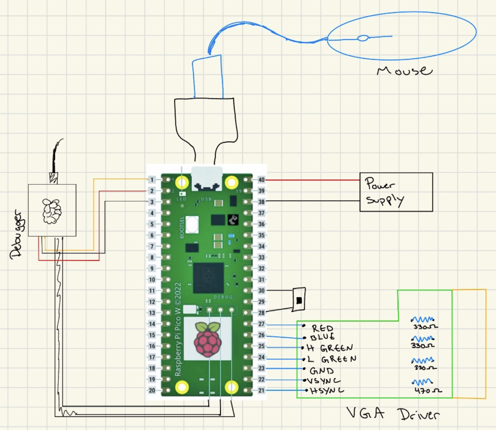 Figure: Pico W and VGA interface hardware
Mechanical Hardware
Preliminary Design
The autonomous drawing car uses a chassis sourced from the lab, likely part of a car kit. We reverse-engineered the chassis in CAD to accommodate a central dry erase marker mount, ensuring the marker tip makes contact with the drawing surface without interfering with wheel motion.
CAD Design
The original CAD model was modified to include a marker holder at the geometric center of the chassis. The mount was designed to be rigid and aligned with the chassis' center of mass, minimizing wobble during movement. Adjustments in CAD focused on ensuring clearance for the motors and wheels while maintaining a simple, manufacturable design.
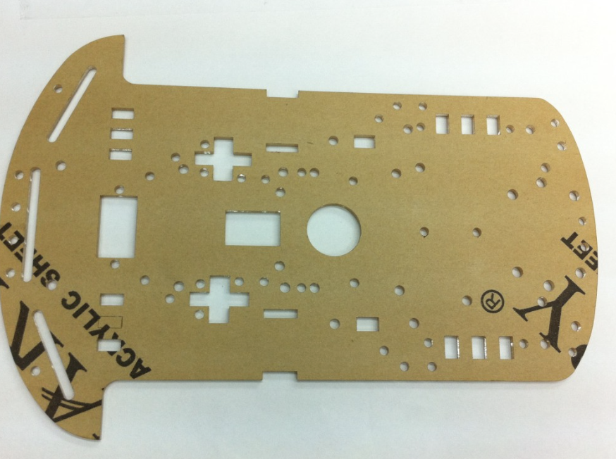 Figure: Chassis
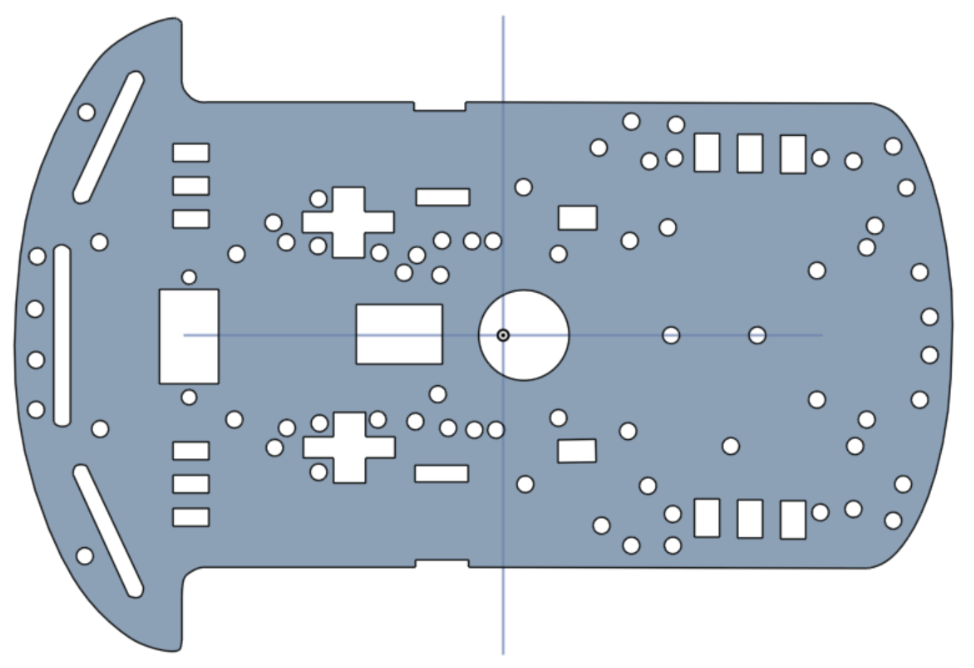 Figure: Reverse engineered CAD
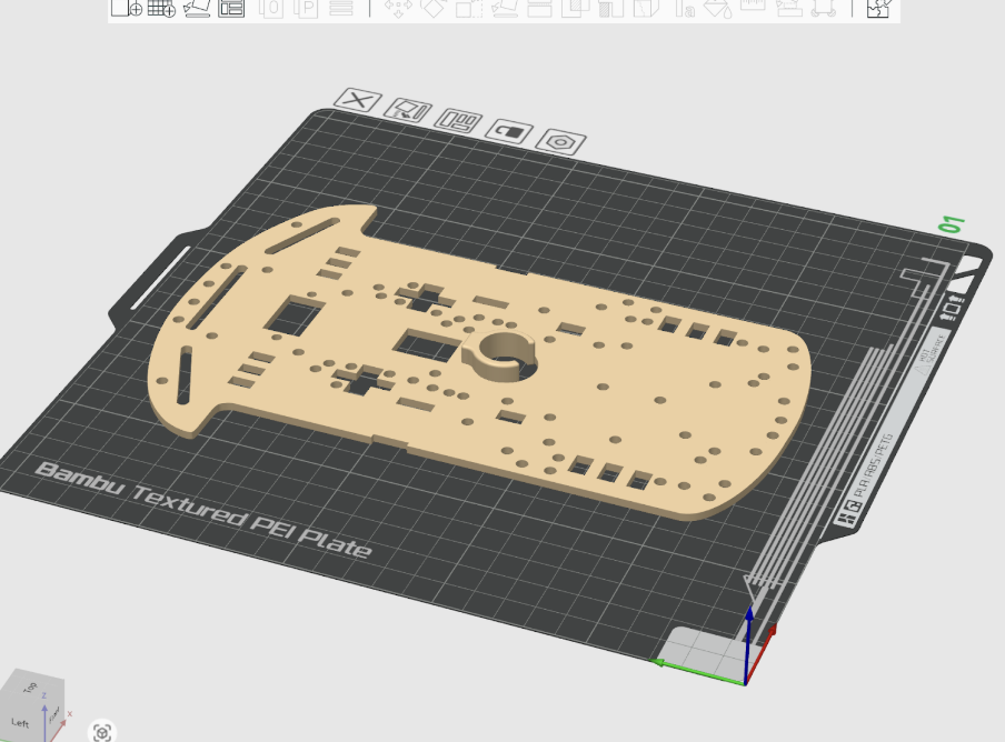 Figure: With dry erase marker mount
Implementation Notes
The modified chassis was printed and assembled using standard lab components. The marker is secured in the mount and can be removed or replaced for maintenance. The mount is fixed in height, but slight manual adjustments were made during testing to ensure reliable contact with the drawing surface.
Code and Design References
All source files retain their original copyright notices where applicable, and this project complies with the terms of all included licenses. Detailed attribution information is documented in picomobile/ATTRIBUTIONS.md and in the References section below. We drew heavily from ECE 4760 course examples provided by Professors Bruce Land and Van Hunter Adams: Professor Land provided USB Host HID examples, UDP data transfer examples using LWIP and protothreads, and the VGA graphics framework. Professor Hunter Adams provided PWM generation examples for motor control, I2C communication patterns, and sensor interfacing examples.
Things We Tried That Did Not Work
Over the final weeks of development, we explored several approaches that ultimately proved ineffective or counterproductive. While these attempts did not make it into the final system, they were critical in shaping our understanding of the problem and guiding us toward more robust solutions.
Continuous Dead-Reckoning Position Integration. Early on, we attempted to continuously update the robot’s global position by integrating forward motion over time using a fixed velocity model. In practice, small variations in motor speed, battery voltage, and surface friction caused position estimates to drift rapidly. Without wheel encoders or closed-loop distance sensing, the accumulated error became large enough that waypoint navigation degraded significantly over longer paths. This led us to abandon continuous integration in favor of discrete waypoint execution with heading correction.
Closed-Loop Heading Control with Aggressive Gains. We initially implemented a proportional-style heading controller with relatively high gains in an effort to achieve fast alignment. While this worked in simulation, the real system exhibited oscillations and jitter due to IMU noise and motor dead zones. The robot would repeatedly overshoot the desired heading, resulting in audible motor chatter and unstable motion. Reducing this to a threshold-based, bang-bang turning strategy produced far more reliable and repeatable behavior.
Driving While Turning Toward a Waypoint. Another attempted improvement was to allow the robot to drive forward while simultaneously correcting its heading, rather than fully aligning before moving. In theory, this should have produced smoother trajectories. In practice, mismatched motor characteristics and uneven friction caused the robot to arc unpredictably, especially at low speeds. This made path execution less consistent than the simpler “turn-then-drive” approach.
Exact Path Following of Dense Waypoints. When streaming dense point data from the drawing interface, we attempted to have the car follow every point exactly. This overwhelmed the control loop and amplified small heading errors, leading to jerky motion and excessive turning. The robot spent more time correcting orientation than making forward progress. This experience motivated the use of waypoint spacing and optional path optimization to reduce unnecessary heading changes.
More Complex Path Optimization Schemes. Beyond nearest-neighbor and 2-opt refinement, we briefly explored more exhaustive path reordering strategies inspired by full TSP solvers. These approaches were either too computationally expensive for our workflow or offered negligible improvement over simpler heuristics, especially given the physical limitations and noise of the robot. The added complexity was not justified by real-world performance gains.
Mechanical Marker Adjustments as a Software Fix. We repeatedly tried to compensate in software for issues caused by marker drag and uneven contact with the drawing surface. No amount of tuning could fully overcome poor marker height or alignment, reinforcing the lesson that some problems are fundamentally mechanical. Once the marker mount was physically adjusted, many previously mysterious control issues disappeared.
Although these approaches did not succeed, each failure clarified system constraints and informed the final design. Many of the project’s most stable features emerged directly from understanding why these ideas did not work on real hardware.
AI Use
Throughout the project, we experimented with two main AI tools: ChatGPT and Cursor. We attempted to use both for a wide range of tasks including hardware troubleshooting, code writing, VGA graphics formatting, and understanding Git workflows.
During the initial brainstorming phase, we used ChatGPT extensively to explore project ideas and generate initial concepts. We also attempted to use it for component selection, but found this approach to be significantly flawed. ChatGPT often hallucinated component specifications or recommended parts that were poorly suited to our requirements, leading us to rely on datasheets and vendor documentation instead.
For code generation, we found both Cursor and ChatGPT to be ineffective. The AI tools frequently produced what we came to call "monkey-paw" code: technically correct code that compiled and ran, but failed to meet our actual design goals or requirements. However, the exercise of prompting the LLM and then realizing its output was inadequate forced us to think more critically about what we were trying to accomplish. This process of identifying the gaps between the AI's output and our needs helped us manually write better code and think through design choices more carefully.
During the main development phase of the final project, attempting to use AI for code generation actually slowed us down. Similar to our experience in previous lab assignments for this course, we found AI tools to be most helpful when used in "Ask mode" for informational questions. Cursor was particularly useful in this context because it could analyze multiple files simultaneously, providing context-aware answers about our codebase. However, we did not use Agent mode and did not accept any code suggestions generated in Ask mode.
ChatGPT proved valuable for addressing side issues unrelated to core development, such as version control workflows, troubleshooting build system problems, and resolving issues with uploading code to the Pico W. For these peripheral tasks, the AI's ability to provide quick explanations and step-by-step guidance was helpful, though we always verified the information against official documentation.
In summary, while AI tools were useful for brainstorming, asking questions, and troubleshooting auxiliary issues, we found them counterproductive for actual code development. The process of working with AI-generated code that was technically correct but functionally wrong ultimately helped us develop a deeper understanding of our system requirements and write more thoughtful, purpose-driven code.
Results of the Design
Test Data, Scope Traces, and Waveforms
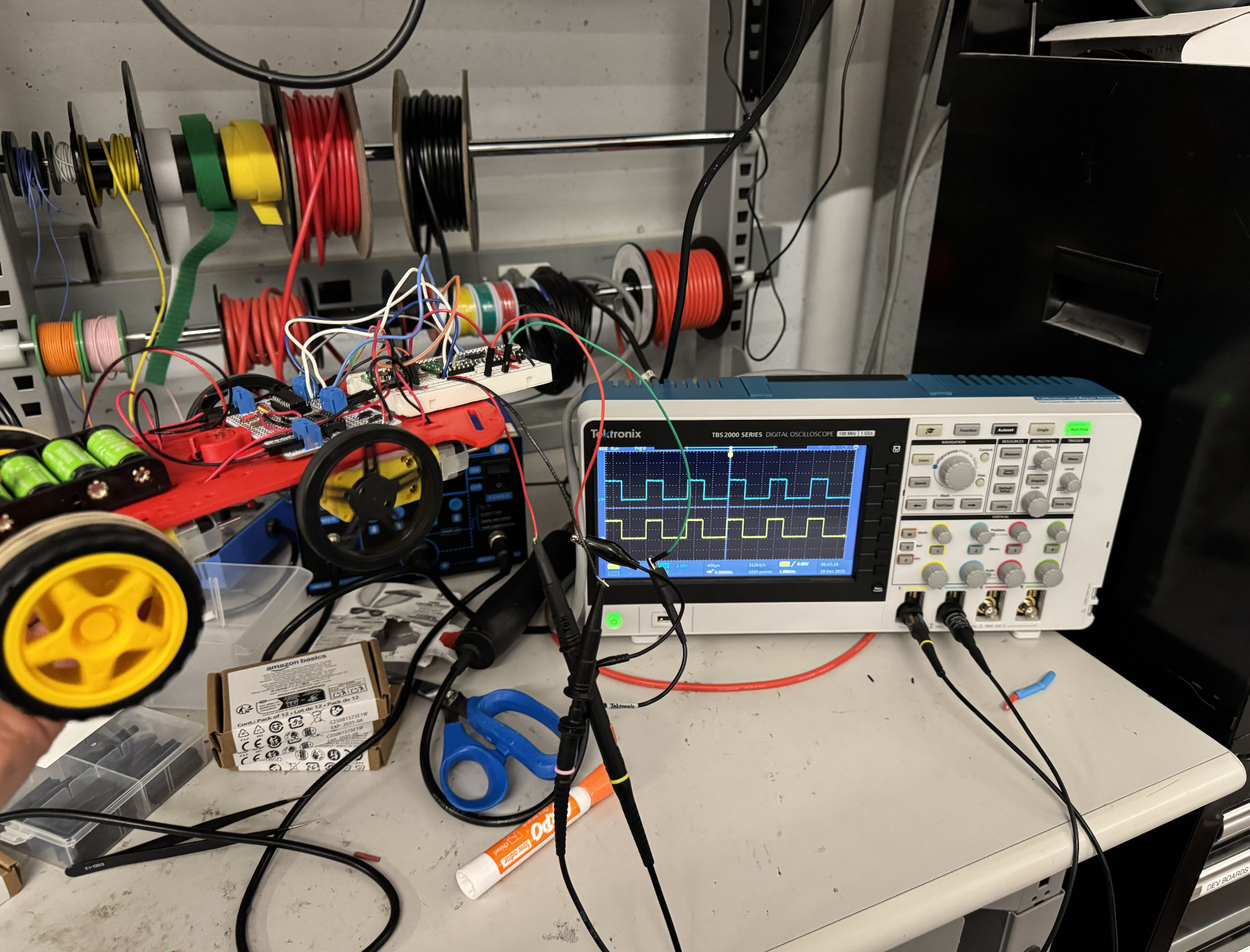 Figure: Scope view of the car outputs during testing
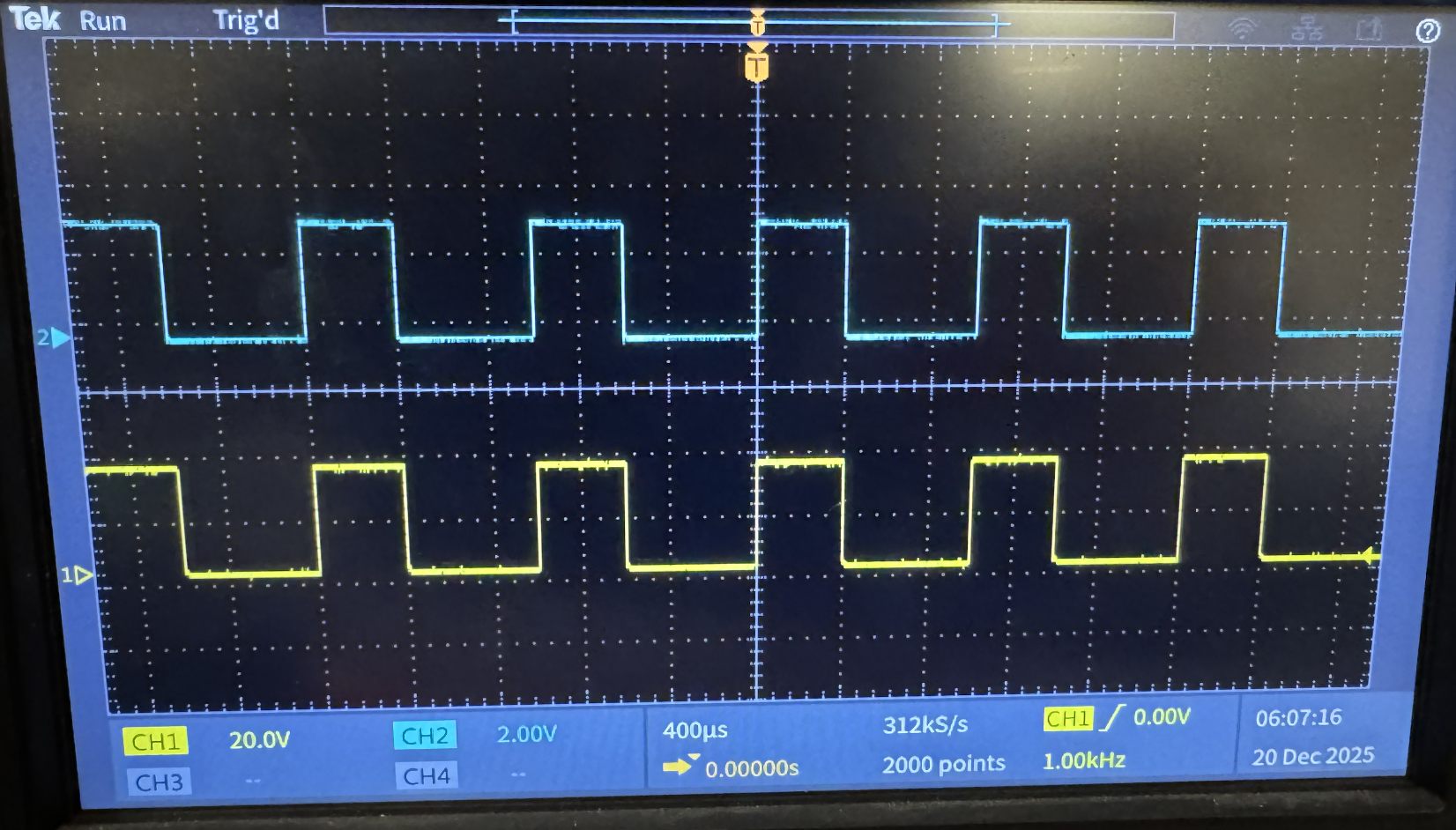 Figure: Detailed PWM waveform trace
Speed of Execution
The speed is adjustable by adjusting the speed of the wheels during the "drive forward" phase. The turning phase takes approximately half a second, but depending on factors like friction between the wheels and the charge of the battery, the angle correction could take longer. If batteries are at a slightly higher voltage than 5V, the car can overshoot its target angle and require additional time to correct.
Accuracy
Without the pen attached, the car can reliably trace out any shape. If you draw a closed shape where the last waypoint on the VGA is where the car started, the car will reliably arrive at the same place it started in real life as well. With the pen attached, inconsistent drag and friction cause issues and lead to reduced accuracy. The additional friction from the marker dragging against the surface introduces position estimation errors, as the timing-based control cannot account for the reduced distance traveled.
Safety Measures
We implemented two switches on the car for safety. One switch connects or disconnects the batteries from the four motors on the car, allowing the motors to be powered off independently. Another switch connects or disconnects the batteries from powering the on-car Pico W. We also used a Schottky diode so that the Pico could safely be connected to both the battery source and be plugged in through micro-USB for programming, preventing damage from multiple power sources.
Usability
The autonomous drawing car performed reliably across all tested functions during final evaluation.
The VGA interface rendered the drawn path clearly with no flicker or visual artifacts. Waypoints generated on the PC-side Pico W were transmitted via UDP with minimal latency; the car responded to path updates almost instantaneously.
IMU-based heading estimation and PWM motor control allowed smooth corrections toward each waypoint. Control loops ran reliably with minimal jitter, and concurrent PWM updates did not interfere with sensor readings or UDP packet handling. Scope traces of the PWM signals confirmed reliable timing across all four motor outputs, validating accurate motor actuation.
In regular mode, the car successfully followed the path as it was drawn, and optimized waypoints ensured minimal travel distance. Additional waypoints could be added iteratively after the car completed its current movement, and the car would incorporate them into its path without restarting. Without the dry erase marker installed, the car followed waypoints accurately, with negligible drift. When the marker was inserted, mechanical misalignment and friction introduced noticeable drift, especially around sharp turns or tight curves.
All GPIO lines and PWM outputs were tested under continuous operation. Sensor timeouts and PWM clamping prevented runaway behavior. The chassis and enclosure effectively protected the electronics and motors, ensuring safe operation during repeated tests.
Interactions via the PC-side interface were intuitive. Users could draw paths, see them updated in real time, and issue new waypoints without restarting the system. The car responded consistently to input commands, making it easy for multiple users to test without supervision.
The system demonstrated effective integration of hardware and software. Visual feedback via VGA was clear, communication latency from PC to car was minimal, and interactions were intuitive. The main limitation observed was the increased drift when the marker was mounted, emphasizing the tradeoff between mechanical simplicity and precise drawing accuracy.
The full demonstration of these capabilities is included in the project demo video.
Conclusions
Design Analysis and Future Improvements
The autonomous drawing car successfully achieved the core objectives we set out in our original proposal: it is mobile, responsive to user input, and capable of following paths in real time with both manual and autonomous control. Integration of motor control, heading sensing, real-time path updates, and VGA feedback resulted in a cohesive system that reliably executed drawn paths with minimal latency. Scope traces confirmed that PWM outputs were stable across all four motors, validating accurate and responsive actuation.
Key Challenges and Adaptations
During development, we encountered multiple challenges that required deviation from our original plan of image-based path extraction. Rather than processing photos to extract waypoints, we pivoted to real-time mouse-driven path input, which simplified input processing while still demonstrating the core autonomous control concepts.
Reverse-engineering the chassis and implementing a dry erase marker mount introduced mechanical drift, particularly on sharp turns, but the overall system remained functional. Electrical issues included accidentally shorting 12 rechargeable batteries, a battery pack, and a USB cable during early testing, which prompted redesigns and reinforced safety procedures. Subsequent solderboard and wiring refinements ensured reliable operation.
Debugging on the Pico W was limited without a serial monitor, requiring the use of the VGA interface and test Pico units for output. UDP communication, motor PWM, and IMU integration were tuned iteratively to minimize latency and drift.
Safety measures such as PWM clamping, sensor timeouts, and careful electrical isolation were enforced to prevent runaway behavior and hardware damage.
Future Improvements
Future improvements could include creating a more intuitive manual control interface, such as arrow keys or on-screen directional buttons, to improve usability. Adjusting or redesigning the marker mount to reduce drift, potentially with an adjustable height mechanism or low-friction holder, would also help. Reinforcing the chassis would further reduce mechanical wobble.
Reflection on Team Effort
Our group collaborated closely throughout the project, sharing responsibilities across hardware, software, and integration tasks. While the project deviated from the initial image-processing goal, the shift allowed us to explore cooperative multitasking, real-time UDP communication, PWM motor control, and IMU-based heading correction in a practical, hands-on way. The final system demonstrates a working, interactive, and modular autonomous drawing platform, providing a strong foundation for future expansions or refinements.
Standards Compliance
Intellectual Property Considerations
Code and Design Reuse
We reused and adapted code from multiple sources. Professor Bruce Land's USB Host HID library was especially helpful, providing the foundation for mouse input handling on the PC-side Pico W. We also used Professor Land's UDP data transfer examples using LWIP and protothreads, which demonstrated efficient, low-latency communication between Pico Ws. The VGA graphics framework was adapted from Professor Hunter Adams' original VGA code, with 16-color modifications by Professor Bruce Land. For motor control, we adapted PWM generation examples from Professor Hunter Adams' ECE 4760 materials, which demonstrated use of the RP2040's hardware PWM peripherals. Sensor interfacing and I2C communication patterns were also informed by Professor Adams' sample code.
The BNO055 IMU driver was adapted from the JRDPropulsion BNO055-RP2040-Library (https://github.com/JRDPropulsion/BNO055-RP2040-Library/blob/main/src/BNO055.cpp), originally written in C++ for Arduino and converted to C for use with the Pico SDK. This driver handled low-level device configuration and data acquisition, allowing us to focus on heading estimation and motor control rather than register-level setup.
UDP networking code was adapted from multiple sources: base UDP code by Andrew McDonnell (2022), UDP echo examples by Stephan Linz (2016), and Raspberry Pi Pico examples. We used the Cornell RP2040 Protothreads library (original by Adam Dunkels, Swedish Institute of Computer Science; Cornell RP2040 version by Bruce Land) for cooperative multitasking. USB host capabilities were implemented using the TinyUSB library by Ha Thach (tinyusb.org). The Raspberry Pi Pico SDK and lwIP networking stack provided the core framework for our system.
Public Domain Code
All code reused in this project is either open source or publicly available. The Raspberry Pi Pico SDK and lwIP networking stack are open source with BSD-3-Clause licenses. The TinyUSB library uses an MIT License. The Protothreads library is open source. All course-provided examples from Professors Bruce Land and Hunter Adams are publicly available for educational use. The BNO055 driver from JRDPropulsion is available on GitHub. All borrowed code retains its original copyright notices and licenses, and this project complies with the terms of all included licenses.
Reverse Engineering and Patent/Trademark Issues
We reverse-engineered a car chassis that was sourced from the lab, likely part of a car kit. We do not know the exact manufacturer, but the chassis appears to be mass-produced and available on Amazon. It does not seem to belong to one particular author or manufacturer, and we found no specific trademarks or patents associated with it. We modified the chassis in CAD to add a central dry erase marker mount, creating our own design for the marker holder. No commercial patents were infringed, and the design remains primarily educational and experimental. All mechanical modifications were fully documented in CAD.
Standards Compliance
The design conformed to relevant embedded systems and safety standards. Motor voltage and PWM signals stayed within the safe limits of the DC motors and H-bridge driver. All circuits operated at low voltages (3.3V logic, 5–12V motor power) to avoid electrical hazards. Mechanical components were secured to prevent sudden shifts, and emergency stop and timeout mechanisms ensured safe operation. While no formal automotive standards were strictly applied, we conceptually followed principles from ISO 26262 for functional safety.
Intellectual Property Considerations
All primary code, control algorithms, and CAD designs were developed by the team. No proprietary IP, patents, or trademarks were used, and nothing required non-disclosure agreements. All borrowed code retains its original copyright notices and licenses (BSD-3-Clause, MIT, etc.). No commercial patents were infringed, and the design remains primarily educational and experimental. All attributions are documented in the source code headers and in the References section below.
Work Distribution
We completed approximately 90% of our work collaboratively in the same room, with all team members contributing to software development, electrical hardware setup, and mechanical integration. While most tasks involved group discussion and shared implementation, certain components saw individual members taking primary responsibility. Ruby Wu designed and CADed the chassis and marker holder, creating the mechanical structure that accommodates the dry erase marker mount. Gebran Kastoun developed the IMU driver, adapting the BNO055 library from C++ to C and integrating it with the Pico SDK for heading estimation. Sarah Zhong implemented the UDP communication system, establishing the wireless protocol for transmitting waypoint data between the PC-side and car-side Pico Ws.
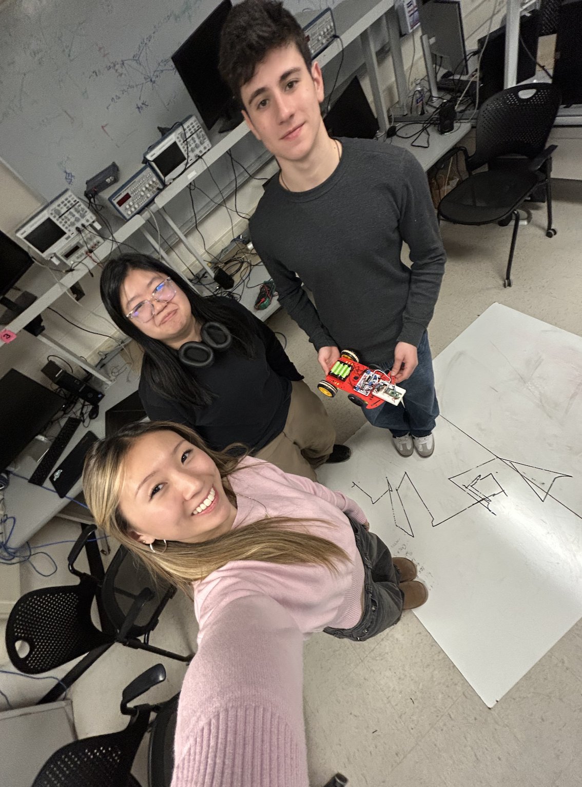 Figure: Team selfie with the car (and an attempt to draw "4760"...)
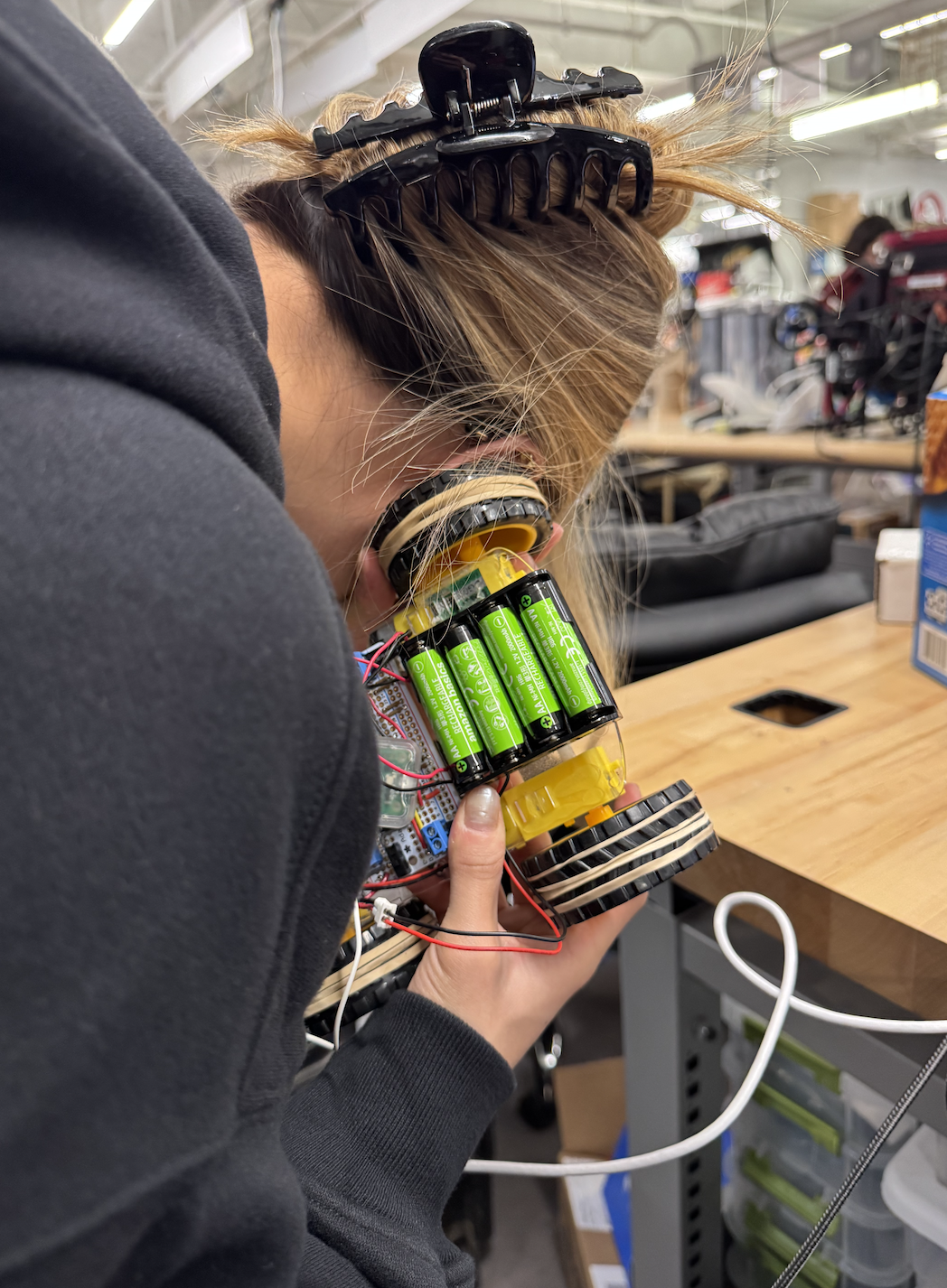 Figure: Sarah listening for a heartbeat on V1 of the car
Appendix A (Permissions)
The group approves this report for inclusion on the course website.
The group approves the video for inclusion on the course YouTube channel.
Additional Appendices
- Commented C and other program listings - Key code sections including path optimization, motor control, and UDP communication
- Complete source code repository (picomobile.zip) - Full project source code including PC-side (udp_and_vga) and car-side (car_and_udp) implementations
- Schematics for hardware external to the Pico board
- List of specific tasks carried out by each team member
References
Data Sheets
- Bosch BNO055 9-DOF Absolute Orientation Sensor Datasheet
- Raspberry Pi Pico W Datasheet
- RP2040 Microcontroller Datasheet
Vendor Sites
- Raspberry Pi Foundation: https://www.raspberrypi.com/
- Bosch Sensortec: https://www.bosch-sensortec.com/
Code/Designs Borrowed from Others
- JRDPropulsion BNO055-RP2040-Library: https://github.com/JRDPropulsion/BNO055-RP2040-Library/blob/main/src/BNO055.cpp (C++ library adapted to C)
- UDP Networking: Andrew McDonnell (2022), Stephan Linz (2016), Raspberry Pi Pico examples (https://github.com/raspberrypi/pico-examples/tree/master/pico_w/wifi/udp_beacon)
- Protothreads: Original by Adam Dunkels (Swedish Institute of Computer Science, 2004-2005), Cornell RP2040 version by Bruce Land (BRL4), Cornell University
- VGA Graphics: Original by Hunter Adams (vha3@cornell.edu), 16-color modifications by Bruce Land (BRL4)
- TinyUSB: Ha Thach (tinyusb.org), https://github.com/hathach/tinyusb
- lwIP: https://savannah.nongnu.org/projects/lwip/
- Raspberry Pi Pico SDK: https://github.com/raspberrypi/pico-sdk
- Professors Bruce Land and Van Hunter Adams' ECE 4760 Examples: USB Host HID (Professor Land), UDP communication (Professor Land), VGA graphics framework (Professors Land and Hunter Adams), protothreads (Professor Land), PWM motor control (Professor Hunter Adams), I2C communication (Professor Hunter Adams), sensor interfacing (Professor Hunter Adams)
Background Sites/Papers
- Raspberry Pi Pico C/C++ SDK Documentation: https://datasheets.raspberrypi.com/pico/raspberry-pi-pico-c-sdk.pdf
- lwIP Documentation: https://www.nongnu.org/lwip/2_1_x/index.html
- TinyUSB Documentation: https://docs.tinyusb.org/
- Protothreads Documentation: https://dunkels.com/adam/pt/
- Cornell ECE 4760 Course Materials: https://people.ece.cornell.edu/land/courses/ece4760/