Introduction

For our ECE 4760 final project, we built a two-wheeled self-balancing robot that can keep itself upright using real-time feedback control. At its core, the robot behaves like an inverted pendulum, so when it starts to tip, it senses the motion and drives its wheels to bring itself back into balance.

This project was a chance for us to bring together many of the ideas we learned throughout ECE 4760 and apply them to a real, physical system. A lot of our design was inspired by earlier labs and lecture material, especially the old inverted pendulum examples discussed in class and on the course website, as well as Lab 3, where we used PID control to stabilize a one-dimensional helicopter. Those exercises gave us intuition for how feedback control behaves in practice and directly shaped how we approached this project.

The robot is controlled by a Raspberry Pi Pico W running a PID controller on the RP2040 microcontroller. Using data from an onboard IMU, the controller continuously estimates the robot’s tilt angle and how fast that angle is changing. We combine accelerometer and gyroscope measurements using a complementary filter, another technique we learned in class, to get a stable and responsive angle estimate. Based on this information, the controller computes motor commands at a high rate to keep the robot balanced.

We also wanted the robot to be interactive rather than just balancing in place. To do this, we built a web-based interface hosted directly on the Pico W, which lets us monitor the robot and adjust parameters in real time. On top of that, we added gesture-based control so a user can influence the robot’s motion to move forward or backwards in regards to the tilt of a device.

Throughout the project, we went through several design iterations. Decisions about robot height, weight distribution, motor placement, and chassis layout all had noticeable effects on control performance, and testing often forced us to revisit earlier choices. The final robot reflects this iterative process and captures what we think ECE 4760 is really about: combining theory, hardware, and software to build something that actually works in the real world.

cartoon-bot

High Level Design

Our high-level design process began with creating a full 3-D CAD model in Onshape. As a team, we wanted to fully think through the mechanical structure of the robot before building anything physically. Modeling the robot in CAD allowed us to reason about dimensions, material choices, weight distribution, and how all of the subsystems would fit together. This step helped us catch several potential issues early, particularly related to motor placement, center of mass, and wiring, before committing to fabrication.

Rather than treating the CAD model as a static drawing, we used it as an iterative design tool. As our understanding of the physics and control requirements improved, we repeatedly revisited the model and adjusted the design to better align with our goals for stability, symmetry, and ease of assembly.

robot-assembly
Initial full CAD assembly showing overall robot structure.

Motor Torque and Weight Constraints

One of the first constraints we considered was whether our motors could realistically support the weight of the robot while still providing enough torque for balance corrections. We selected 48:1 DC gear motors rated at a maximum output torque of 0.078 N·m and paired them with wheels of radius 5 cm (0.05 m).

To understand what this meant in practice, we related motor torque to the force applied at the wheel–ground interface using the standard torque relationship:

\( \tau = F r \)

\( F = \frac{\tau}{r} \)

\( F_{\text{motor}} = \frac{0.078}{0.05} = 1.56 \text{ N} \)

Figure 1: Torque-to-force relationship at the wheel.

Since our robot uses two motors, the total available horizontal force is approximately:

\( F_{\text{total}} = 2 \times 1.56 = 3.12 \text{ N} \)

Figure 2: Combined force from both motors.

The completed robot had a total mass of approximately 3 lb (1.36 kg), corresponding to a gravitational force of:

\( F_g = mg = (1.36)(9.81) \approx 13.3 \text{ N} \)

Figure 3: Gravitational force acting on the robot.

At first glance, this might suggest that the motors are insufficient; however, a self-balancing robot does not require the motors to lift the robot vertically. Instead, the motors generate horizontal acceleration of the wheels to correct angular deviations of the inverted pendulum system. Only a fraction of the robot’s weight contributes to the required corrective torque at small tilt angles.

This understanding guided our design decisions and gave us confidence that, with appropriate height selection and PID control, our motors would be capable of stabilizing a 3 lb robot. This was ultimately confirmed through experimental testing.

Logical System Structure

From a system-level perspective, the robot is organized as a closed-loop feedback system. Sensor data from the IMU is continuously sampled and filtered to estimate the robot’s orientation. This estimate is passed to the PID controller, which computes a corrective control signal. That signal is then translated into PWM commands that drive the motors, completing the feedback loop.

This logical structure influenced both the hardware and software design. Mechanically, we aimed to create a symmetric, predictable platform so that the control assumptions would hold. In software, we prioritized deterministic timing and consistent sampling rates to ensure stable controller behavior.

Effect of Robot Height on Stability

With motor limitations in mind, we spent significant time discussing how tall the robot should be. Height plays a major role in the dynamics of a self-balancing robot because it determines the location of the center of mass.

If the robot is too tall, the center of mass is higher, which increases the gravitational torque during tilt and demands larger corrective torques from the motors. If the robot is too short, the center of mass lies close to the wheel axle, reducing the gravitational restoring torque and making the system more sensitive to noise, disturbances, and control latency.

We ultimately chose a moderate height that struck a balance between these two extremes. This provided a measurable tilt response for the controller while remaining within the torque capabilities of our motors.

CAD Iterations and Motor Orientation

During CAD development, we explored several motor mounting configurations. One issue we noticed early was that the motor shafts were slightly offset within the motor housings rather than being centered.

One idea we considered was mounting the motors horizontally but in opposite orientations so that the shaft offsets would cancel each other out. While this approach was theoretically sound, it added mechanical complexity and made precise alignment more difficult.

We ultimately decided to mount the motors vertically, which ensured symmetry about the center of the robot and simplified both the mechanical assembly and mass distribution. This decision required us to revise our initial CAD design, but it resulted in a cleaner and more predictable structure.

Chassis Design and Fabrication

For the overall chassis, we chose to use clear acrylic (plexiglass). The final mechanical assembly consists of three main acrylic plates forming the body of the robot, six acrylic interconnect pieces used to attach the motors, four M5 threaded rods, twenty-four M5 nuts, and plastic adhesive for rigid bonding.

Clear acrylic was chosen primarily because it allowed us to easily see internal components during assembly and testing. This was especially useful during debugging, as we frequently needed to inspect wiring, motor drivers, and power connections without disassembling the robot. Additionally, acrylic can be precisely fabricated using a laser cutter, allowing us to quickly iterate on our design.

DXF files exported from our Onshape CAD model were submitted to the Rapid Prototyping Lab for laser cutting. The design intentionally includes slits and openings in the three main plates to allow wires from the motor circuit, IMU, and battery pack to pass cleanly between layers.

main-frame
Main frame DXF used to mount motors and wheels.
support-frame
Supporting frame DXF for motor driver circuit, IMU, and battery pack.
connector
Connector pieces used to attach motors to the main chassis.

Mechanical Adjustments for Tuning and Testing

As we started tuning the PID controller, it became clear very quickly that the robot was going to fall a lot before it worked well. To avoid damaging the chassis or electronics during these early tests, we added protective foam around the edges of the robot. This gave the robot a softer landing when it fell and let us safely experiment with more aggressive PID gains without worrying about breaking anything.

foam
Foam To Protect Robot on Falls.

We also spent time experimenting with where to place the heavier components on the robot. The battery pack, which is one of the heaviest parts, was mounted on the top level, while the IMU and motor driver circuit were placed on the middle level. Putting more weight higher up increased the height of the center of mass, which made the robot’s tilting motion more noticeable and easier for the controller to react to during balancing.

adjustments
Placement of Hardware Components.

In practice, mounting everything perfectly centered was harder than we expected. Small offsets from wiring, connectors, and mounting holes caused slight imbalances that showed up during testing. Even small asymmetries in weight distribution had a noticeable effect on how the robot behaved.

To correct this, we made a series of small mechanical adjustments by adding extra M5 nuts and threaded rods to the top level of the robot. Although this slightly increased the overall weight, our main goal was to counteract existing weight offsets rather than add mass unnecessarily. By placing these additions strategically, we were able to better center the robot’s mass and improve balance consistency.

balancingcomponents
Added Weight for Balance.

These adjustments reinforced how closely the mechanical design and control performance are connected. Many of the improvements we saw during tuning came not just from changing PID gains, but from making small, deliberate changes to the physical structure of the robot.

Hardware Design

hardware-diagram
Figure : Full solderboard assembly showing all components
Our robot's circuit is built onto one solderboard - containing our motor circuit and Pico-W controller. The above figure shows the final breadboard with labels indicating wires to off-board components (motors, imu, etc.). Below is a listing of connections made from the Pico-W to the rest of the circuit, as well as a circuit diagram for the motor drivers.

  • Pin 3: 6 Volt COM
  • Pin 6: 4N35-0 1 (Anode)
  • Pin 7: 4N35-1 1 (Anode)
  • Pin 11: MPU-6050 SDA
  • Pin 12: MPU-6050 SCL
  • Pin 36: MPU-6050 3.3V
  • Pin 39: 5V (through diode)
Figure : Pico-W Connection Listing
hardware-diagram
Figure #: Motor driver/H-Bridge circuit adapted for two motors.

Our motor circuit was adapted from the Inverted Pendulum Lab that has been offered in previous semesters of ECE4760 with Hunter Adams. Our changes include adding a second H-Bridge to drive our second motor.
We have two PWM channels coming from the Pico-W (discussed in software design) that are optically isolated from our noisy motor circuit using two 4N35 optocouplers. One PWM signal drives input A of both L9110 H-Bridges, and the other drives input B. The L9110s that we chose were convenient because they included hardware safeguards that prevent shorting power to ground in the case that both inputs are high - although our software ensures that this never happens (discussed later). When we enable PWM0, the H-Bridge allows IA through - sending current through our motors from IA to IB. When we enable PWM1, the H-Bridge allows IB through, sending current through our motors from IB to IA. This enables forward and backwards movement, essential for keeping our bi-ped standing up.
Concerning power - our entire robot runs off one 6V 4-AA battery pack. Our motors are rated for 12V, but they recieved enough power from this pack to keep our robot upright. Running these motors at half power also allowed the batteries to last longer (lower current draw, around 550 mA including the Pico-W). To power the Pico-W we use one 1N diode for a small voltage drop to around 5.5V, which was safe for powering it via the VSYS pin. This diode also protected the Pico-W from trying to source current to the motors running off the same battery pack.

Software Design

The onboard software of this robot is comprised of two parallel threads of execution (using both cores on the Pico-W), as well as several "protothreads" responsible for scheduling various tasks on each core. Below is a general overview of the responsibilities of each core, as well as a listing and description of each thread running on that core. Note that our TCP server was adapted from a project originally by Professor Bruce Land for the RP2350 which is documented here. Our changes include developing two new web pages to display, and recieving HTTP requests from a Pico-W client.

Core 0: Handles networking and debugging information.
  • DHCP Server (non-protothread): Initializes a DHCP server listening on Core 0 for any incoming DHCP requests and responding appropriately.
  • DNS Server (non-protothread): Initializes a DNS server listening on Core 0 for handling DNS traffic to our mini-server.
  • TCP Server (non-protothread): Initializes a TCP server listening on Core 0 for handling HTTP GET requests and sending replies.
  • Serial Protothread: Thread handling printing debug information to the serial output, used extensively during development.
Core 1: Handles high-precision, high-bandwidth PID calculations.
  • PID ISR: runs whenever our PWM channels wrap ( approximately every 0.83ms ) reading sensors and computing our error function.
Figure : Onboard Software Listing

PID Control

PID control is the heart of every self balancing robot. Core 1 of our onboard Pico handles the PID. Our ISR triggers at a target speed of 1.2kHz, giving us enough time to detect and respond to the angle changes of the robot. Our on_pwm_wrap function reads raw data from our accelerometer and gyroscope, approximates the devices actual angle via a complementary filter (discussed later), then executes the pid_step function that handles error computation and control response. Our PID function runs at a constant rate, aligned with our angle sampling and PWM wrap. We use hardware interrupts to ensure that our controller executes at a consistent rate, since the integral and derivative components depend on a fixed time constant τ.

\( C = \mathrm{clamp}\!\left((K_p \cdot e) + (K_i \cdot \Sigma e) + (K_d \cdot \Delta e),\ \min,\ \max\right) \)

Figure : PID Control (C) general equation.

On every loop iteration, we compute the error, update our accumulated error, and sample the gyroscope for ∆θ. We then compute our control output according to the above equation.
One of the most crucial parts of our PID implementation is a symmetric range for our control value around 0. This allows our controller to produce positive and negative control values, which we can interpret as forwards/backwards drive based on the sign of the value. This logic is handled in pid_step function. This symmetric range introduced some "friction" at duty cycles in the range of roughly (-1000, 1000) that were too small to actually spin our motors. This caused increased wind-up time and slower responses overall. We overcame this by applying a +1000 unit offset to our duty cycle as we set the PWM Channel output, then capping the PID at our maximum duty cycle minus 1000 (in our case, 4000). This clamps our duty cycle outside of this range, significantly increasing reaction speeds.
Another obstacle that we encountered with our dual-motor setup was differences in the reaction properties of our motors when rotating them forwards versus backwards. We found that one direction was considerably less reactive, causing our robot to favor falling towards that side even when optimally tuned. We resolved this issue by running a secondary P,I, and D calculation with smaller gains that could be used to offset the output duty cycle for the less favorable direction. This worked well, and resulted in us achieving the stability demonstrated in our demo video.

Complementary Filter

We utilize a complementary filter to estimate the robot's orientation using both acelerometer and gyroscope data. The gyroscope produces a clean signal that measures the rate of change in orientation but accumulates drift over time. The accelerometer measures the absolute orientation relative to Earth’s gravity but introduces substantial high-frequency noise. To combine the strengths of both sensors, we high-pass filter the gyroscope data (removing long-term drift) and low-pass filter the accelerometer data (removing high-frequency noise). The resulting estimate provides both accuracy and responsiveness. This is implemented by weighting the gyroscope estimate heavily (0.999) and the accelerometer estimate lightly (0.001):

\( \theta_{\text{filtered}} = 0.999\,(\theta_{\text{prev}} + \Delta\theta_{\text{gyro}}) + 0.001\,(\theta_{\text{accel}}) \)

Figure: Complementary Filter general equation.

The below block diagram illustrates the actual filtering process, including all inputs and outputs to the filter.

complementary-filter
Figure: Block diagram for the complementary filter implemented by our program. From Adams, Complementary Filters

Gesture Hardware Configuration

The gesture input device is implemented on a breadboard using a Raspberry Pi Pico W and an MPU6050 Inertial Measurement Unit (IMU). The Pico W serves as both the sensing and processing unit, while the MPU6050 provides 3-axis accelerometer and gyroscope measurements for gesture recognition.

The IMU is interfaced to the Pico W using the I2C protocol operating at 3.3 V logic levels. Power and signal connections are made directly between the Pico W and the MPU6050 breakout board.

Electrical Connections

MPU6050 Pin Pico W Pin Description
VCC 3.3 V Power supply for IMU (3.3 V logic)
GND GND Common electrical ground
SCL GPIO 9 (I2C SCL) I2C clock line
SDA GPIO 8 (I2C SDA) I2C data line

Physical Layout

The Pico W and MPU6050 are mounted on a solderless breadboard to allow rapid prototyping and iterative development. Short jumper wires are used for the I2C lines to minimize noise and signal integrity issues. The shared ground reference ensures stable sensor measurements and reliable communication.

This hardware configuration allows the Pico W to continuously acquire inertial measurements, perform on-board sensor fusion, and transmit gesture commands wirelessly without the need for external processing hardware.

Raspberry Pi Pico W connected to MPU6050 IMU on a breadboard using I2C
Figure 1: Breadboard-based gesture hardware consisting of a Raspberry Pi Pico W interfaced with an MPU6050 IMU over I2C.

Gesture Control Software

This system implements a client-side inertial gesture interface on a Raspberry Pi Pico W. The Pico W acquires raw inertial measurements from an MPU6050 IMU via I2C, performs fixed-point sensor fusion to estimate orientation, discretizes the estimated state into gesture events, and transmits those events to a remote server using HTTP over Wi-Fi. The Pico W acts exclusively as a network client, initiating all communication.

The signal path can be summarized as:
IMU → Fixed-Point Sensor Fusion → Gesture State Machine → HTTP Client


IMU Data Acquisition Layer

Hardware Interface and Configuration

The MPU6050 is interfaced over I2C using the RP2040’s hardware I2C controller. During initialization, the device is configured as follows:

  • Power management disabled (device wake-up)
  • Accelerometer full-scale range: ±2 g
  • Gyroscope full-scale range: ±250 deg/s
  • Sample rate divider configured for 1 kHz internal sampling

All configuration writes are performed using blocking I2C transactions to ensure deterministic sensor state before data acquisition begins.

1.2 Raw Measurement Acquisition

Accelerometer and gyroscope data are read from the MPU6050 using register auto-increment:

  • Accelerometer: registers 0x3B–0x40
  • Gyroscope: registers 0x43–0x48

Each axis measurement is reconstructed from two consecutive 8-bit registers into a signed 16-bit value. The data is then converted into Q15 fixed-point format, allowing subsequent signal processing to be performed without floating-point hardware and improving real-time determinism.

The raw measurement vectors are represented as:
a = [ax, ay, az],   ω = [ωx, ωy, ωz]


Sensor Fusion and Orientation Estimation

Accelerometer-Based Tilt Estimation

The instantaneous tilt angle is derived from accelerometer measurements using the Y–Z plane:

θacc = atan2(-ay, -az)

This angle provides an absolute reference to gravity but is subject to high-frequency noise and transient linear acceleration.

Gyroscope Integration

Gyroscope data provides angular velocity around the X-axis. Incremental angular displacement is computed as:

Δθgyro = ωx · Δt

where Δt is assumed constant and approximately 1 ms. This integration provides smooth short-term motion tracking but accumulates bias-induced drift over time.

Complementary Filter Implementation

To combine the strengths of both sensors, a first-order complementary filter is implemented in fixed-point arithmetic:

θk = α(θk-1 − Δθgyro) + (1 − α)θacc

  • α = 0.999
  • θk is the filtered orientation estimate

The filter effectively acts as a high-pass filter on gyroscope data and a low-pass filter on accelerometer data. To prevent instability and large transients, the filtered angle is saturated to:

θk ∈ [−5°, +5°]

This filtered output (complementary_angle) represents the system’s internal orientation state.


Gesture Detection and State Quantization

Continuous-to-Discrete State Mapping

Gesture detection maps the continuous orientation estimate into a discrete state:

Condition Gesture
θ > 0 FORWARD
θ < 0 BACKWARD
θ = 0 NONE

This reduces a continuous sensor signal into a finite command alphabet suitable for network transmission and downstream control.

3.2 Edge-Triggered Gesture Emission

To prevent command flooding and oscillatory behavior, gesture transmission is edge-triggered. The system maintains the last transmitted gesture and emits a new command only when a state transition occurs:

Gk ≠ Gk-1

This makes gesture output event-driven, improving robustness under noisy sensor conditions.


Wireless Communication Subsystem

Network Role and Initialization

The Pico W operates in station (STA) mode, connecting to an external access point using WPA2 authentication. The CYW43 networking stack is initialized at startup, and all subsequent communication occurs through a single TCP/IP context.

The Pico W does not listen for inbound connections and does not host a server; it functions solely as a client.

HTTP-Based Gesture Transport

Gesture events are transmitted to a remote server using synchronous HTTP GET requests. Each request encodes the gesture state in the URL query string:

  • GET /msg?msg=FORWARD
  • GET /msg?msg=BACKWARD

The HTTP client blocks until a response is received or the server closes the connection. Successful transmission is inferred from standard HTTP client return codes. This design prioritizes simplicity and debuggability over latency and bandwidth efficiency.


Execution Model and Timing

The system runs in a single-threaded polling loop at approximately 10 Hz. Each loop iteration performs:

  1. Blocking I2C read of IMU data
  2. Fixed-point sensor fusion update
  3. Gesture classification
  4. Conditional HTTP request transmission
  5. Fixed delay (sleep_ms(100))

This sequential model ensures deterministic ordering but introduces latency bounded by the loop period and network transaction duration.


Design Constraints and Extensions

Current Constraints

  • Fixed Δt assumption for gyroscope integration
  • Polling-based IMU acquisition despite interrupt configuration
  • Binary gesture classification without hysteresis/dead zone
  • Relatively high-latency HTTP transport

Potential Extensions

  • Interrupt-driven IMU sampling
  • Adaptive complementary filter gain
  • Hysteresis/dead-zone gesture thresholds
  • Non-blocking or UDP-based communication
  • Extension to multi-axis and compound gestures

Results

Our efforts culminated in a very consistent machine capable of keeping itself upright for more than 15 minutes. We are confident that our robot would remain stable for the duration of its battery life if given the chance. Our wireless tuning and control interface is robust, and made the somewhat monotonous process of tuning a PID controlled robot much easier. This embedded server implementation enabled us to meet one of our original goals - making the robot fully untethered. The final product is capable of moving freely around its space (to the extend that its single axis of movement allows). Our gesture control mechanism is also satisfying, producing the "segway"-like motion we set out to implement in our original project proposal. The robot was capable of recovering from slight pushes relatively quickly, although it's resilience did not quite live up to our goals for this short project.

There are several areas that we planned on improving the robot if we had the time. We list them here for completeness, and for the reference of others.

  • Turning: By introducing two additional PWM channels to our complete circuit, we could have had split control of the motors, allowing us to slow one side down to turn in that direction. We already observed this behavior caused by the motors we used not responding identically to the output signal.
  • Better Motors: The motors we used were capable of holding the robot up, but they lacked torque in situations where it was crucial (such as being shoved). By the time we realized this, there was not enough time left to order newer motors. With some more torquey motors, we believe the robot would have been more stable.
  • Better Networking: Our onboard server has the tendency (in our experience) to occasionally crash or become unresponsive, requiring a power cycle to come back online. We propose that this could be resolved with a failsafe in software that checks server status and tries to restart automatically. We also note that these networking issues may have been caused by the very "noisy" environment in which the robot was tested, and may not be a problem in more normal locations.

<

Conclusion

This project successfully met our primary goal of designing and implementing a two-wheeled self-balancing robot capable of maintaining upright stability using real-time feedback control. The final system demonstrated stable balancing behavior under nominal conditions, supported forward and backward motion through gesture-based input, and allowed real-time parameter tuning through an onboard web interface. Overall, the robot’s behavior aligned closely with our expectations based on the inverted pendulum model and prior laboratory experience, particularly in terms of responsiveness, controllability, and sensitivity to mechanical design choices.

That said, the project also revealed several areas where our expectations required adjustment. In practice, the robot’s performance was far more sensitive to mechanical asymmetries, sensor noise, and actuator nonlinearities than idealized models suggested. Differences in motor response between forward and backward rotation, small offsets in mass distribution, and latency introduced by network interactions all had measurable effects on stability. While these challenges were ultimately mitigated through secondary PID compensation, mechanical rebalancing, and gesture command timeouts, a future iteration of this project would benefit from more precise mechanical fabrication, matched motors, and an explicit treatment of actuator dead zones during the initial design phase rather than retrofitting solutions later.

From a software perspective, our use of a complementary filter and high-frequency, interrupt-driven PID control met expectations and proved robust under real-world conditions. However, the fixed-step assumption used for gyroscope integration and the polling-based IMU acquisition represent simplifications that could be improved. In a future design, we would likely implement interrupt-driven sensor sampling and a more adaptive sensor fusion approach to further improve accuracy and reduce latency. Additionally, replacing blocking HTTP requests with a non-blocking or lower-latency communication protocol could improve responsiveness for gesture-based control.

Conformance to Standards and Best Practices

Our design conforms to standard embedded systems and electrical engineering practices emphasized in ECE 4760. All circuitry operated within specified voltage and current limits for the Raspberry Pi Pico W and peripheral components. The MPU6050 IMU was interfaced using standard I2C communication at 3.3 V logic levels, and proper grounding practices were followed to ensure signal integrity. Motor driver isolation using optocouplers reduced noise coupling between the high-current motor domain and sensitive control electronics, aligning with best practices for mixed-signal embedded systems.

From a software standpoint, we adhered to real-time design principles by using hardware interrupts for time-critical PID execution and separating networking and control tasks across the RP2040’s dual cores. This architectural separation helped ensure deterministic control timing despite the presence of networking and user-interface code.

Intellectual Property Considerations

This project made use of prior work and publicly available resources in a transparent and ethical manner. Portions of the networking infrastructure were adapted from example code and prior projects developed by Professor Bruce Land and course staff for ECE 4760 and related platforms. These materials are intended for educational use and are effectively in the public domain for course projects. Conceptual inspiration was also drawn from inverted pendulum examples discussed in lectures, course notes, and earlier laboratory exercises.

No proprietary or closed-source code was used, and no non-disclosure agreements were required to obtain hardware components or documentation. All hardware components, including the Raspberry Pi Pico W, MPU6050 IMU, and motor drivers, are commercially available with publicly documented interfaces. We did not reverse-engineer any protected designs, nor did we encounter patent or trademark restrictions relevant to this project.

While self-balancing robots and gesture-based control systems are well-established concepts, this project does not pursue novel mechanisms or algorithms that would clearly warrant patent protection. Instead, its value lies in the integration and application of known techniques in an educational context. As such, no patent opportunities were identified or pursued.

Broader Perspective and Real-World Applications

Beyond the technical implementation, this project encapsulated the broader educational goals of ECE 4760. The course emphasized that microcontrollers are not merely programming targets, but central components in larger cyber-physical systems that span disciplines. Through this project, we gained a deeper appreciation for how electrical engineering interacts with mechanics, control theory, human–computer interaction, and networking.

Gesture-controlled self-balancing systems have clear real-world relevance, with applications in personal mobility devices, assistive robotics, autonomous platforms, camera stabilization systems, and human–machine interfaces. The principles explored here—sensor fusion, real-time control, and intuitive user input—are foundational to modern robotics and embedded systems.

In conclusion, this project represents a culmination of the technical, conceptual, and practical lessons of ECE 4760. It challenged us to move beyond theory, confront real-world imperfections, and iteratively refine a system until it worked reliably. The experience has significantly shaped how we approach embedded systems design and strengthened our perspective on engineering as an interdisciplinary and deeply integrative discipline.

Appendix A: Permissions

The group approves this report for inclusion on the course website.

The group approves the video for inclusion on the course youtube channel.

Appendix B

Contributions

  • Stephen Barlett: Implemented most of the onboard software, including the PID controller and web interface. Also implemented the full onboard circuit on a breadboard, and then the final product on a solderboard. Finally, tuned the robot to its final state.
  • Jamayne Gyimah-Danquah: Worked on the hardware design and the code for the Gesture Control feature of the project
  • Md Shad: Focused on the mechanical side of the project and the overall physical design of the robot. He designed the robot’s CAD model and used it to think through the chassis layout, motor placement, and weight distribution before anything was built. Md also handled the fabrication process by preparing the parts for laser cutting and assembling the main frame and body of the robot from the acrylic components. Along the way, he worked through the physics behind the self-balancing system, including center-of-mass considerations, motor torque limits, and inverted pendulum behavior. This helped shape the high-level design and ensured the final mechanical structure worked well with the control system.

References

AI Acknowlegement

Throughout the project, we used AI tools as a support resource for analysis, debugging, and documentation rather than as a replacement for our own design work. AI assistance was frequently used to help reason through bugs in our code, interpret compiler and runtime errors, and understand unexpected behavior in complex sections involving interrupts, networking, and real-time control, which significantly sped up the debugging process. We also relied on AI when working with the Pico W’s Wi Fi subsystem, using it to better understand how access point configuration choices such as channel selection, IP addressing, and network setup affected connection stability and reliability. This helped us experiment with and refine our network configuration to achieve more consistent connectivity between devices. In addition, AI was used to help format and organize the project website, including adjusting image placement, improving layout consistency, and refining captions and text for readability. All core system design, control logic, hardware integration, and final implementation decisions were ultimately developed, tested, and validated by our team.

Vendors

  • Amazon: Plexiglass, structural metal rods.
  • Lab supplies: Motors, H-bridges, Optocouplers, solderboard, wheels.

Code

gesture.c
#include <math.h>
#include "gesture.h"

const char* gesture_name(gesture_t g) {
    switch (g) {
        case GESTURE_FORWARD:  return "FORWARD";
        case GESTURE_BACKWARD: return "BACKWARD";
        case GESTURE_LEFT:     return "LEFT";
        case GESTURE_RIGHT:    return "RIGHT";
        case GESTURE_NONE:
        default:               return "NONE";
    }
}

gesture_t detect_gesture(float ax, float ay, float az_ignored) {
    const float THRESH_FB = 0.25f;

    float abs_ax = fabsf(ax);
    float abs_ay = fabsf(ay);

    if (abs_ay > THRESH_FB && abs_ay >= abs_ax) {
        return (ay > 0) ? GESTURE_FORWARD : GESTURE_BACKWARD;
    } else {
        return GESTURE_NONE;
    }
}
imu_filter.c
#include <math.h>
// imu_filter.c
#include <math.h>
#include "imu_filter.h"
#include "mpu6050.h"

// Raw IMU measurements (15.16 fixed-point, accel in g, gyro in deg/s)
fix15 acceleration[3], gyro[3];

// Filter state
fix15 accel_angle, gyro_angle_delta;
fix15 complementary_angle;
fix15 filter_acc_z, filter_acc_y;

// These are defined in some common file in your project, e.g. globals.c
// fix15 oneeightyoverpi = float2fix15(180.0f / 3.14159265358979f);
// fix15 zeropt001       = float2fix15(0.001f);
// fix15 zeropt999       = float2fix15(0.999f);

void imu_filter_init(void)
{
    // Make sure MPU is already reset/configured before calling this
    mpu6050_read_raw(acceleration, gyro);

    filter_acc_y        = acceleration[1];
    filter_acc_z        = acceleration[2];
    accel_angle         = 0;
    gyro_angle_delta    = 0;
    complementary_angle = 0;
}

static void complementary_filter(void)
{
    // Low-pass filter Y and Z acceleration (simple IIR with >>4 ~ 1/16)
    filter_acc_y = filter_acc_y + ((acceleration[1] - filter_acc_y) >> 4);
    filter_acc_z = filter_acc_z + ((acceleration[2] - filter_acc_z) >> 4);

    // Accelerometer angle (atan2 in radians -> degrees)
    accel_angle = multfix15(
        float2fix15(atan2(-filter_acc_y, filter_acc_z)),
        oneeightyoverpi
    );

    // Gyro angle increment (gyro[0] in deg/s * dt ≈ 0.001 s)
    gyro_angle_delta = multfix15(gyro[0], zeropt001);

    // Complementary filter
    complementary_angle =
        multfix15(complementary_angle - gyro_angle_delta, zeropt999) +
        multfix15(accel_angle, zeropt001);
}

void imu_update_and_filter(void)
{
    
    mpu6050_read_raw(acceleration, gyro);

    complementary_filter();
}
pid_controller.c

/**
 * V. Hunter Adams (vha3@cornell.edu)
 * 
 * This demonstration utilizes the MPU6050.
 * It gathers raw accelerometer/gyro measurements, scales
 * them, and plots them to the VGA display. The top plot
 * shows gyro measurements, bottom plot shows accelerometer
 * measurements.
 * 
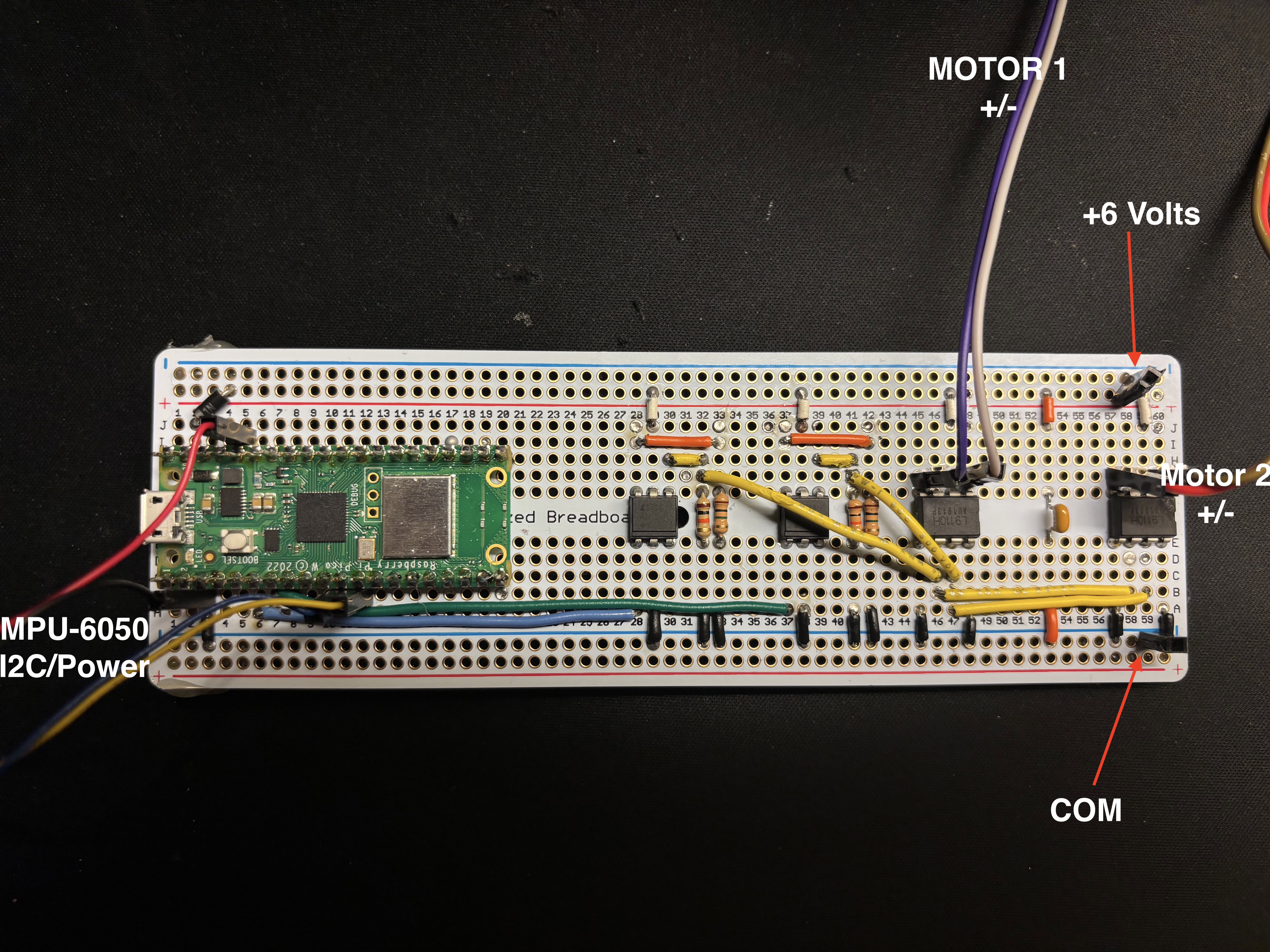
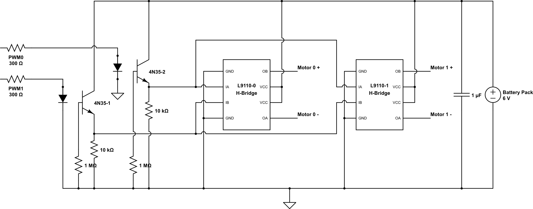
 * HARDWARE CONNECTIONS
 *  - GPIO 16 ---> VGA Hsync
 *  - GPIO 17 ---> VGA Vsync
 *  - GPIO 18 ---> 470 ohm resistor ---> VGA Green
 *  - GPIO 19 ---> 330 ohm resistor ---> VGA Green
 *  - GPIO 20 ---> 330 ohm resistor ---> VGA Blue
 *  - GPIO 21 ---> 330 ohm resistor ---> VGA Red
 *  - RP2040 GND ---> VGA GND
 *  - GPIO 8 ---> MPU6050 SDA
 *  - GPIO 9 ---> MPU6050 SCL
 *  - 3.3v ---> MPU6050 VCC
 *  - RP2040 GND ---> MPU6050 GND
 *  - GPIO 14 ---> H-Bridge Forward
 *  - GPIO 15 ---> H-Bridge Backward
 * 
 * 
 * 
 */


// Include standard libraries
#include <stdio.h>
#include <stdlib.h>
#include <math.h>
#include <string.h>
// Include PICO libraries
#include "pico/stdlib.h"
#include "pico/multicore.h"
// Include hardware libraries
#include "hardware/pwm.h"
#include "hardware/dma.h"
#include "hardware/irq.h"
#include "hardware/adc.h"
#include "hardware/pio.h"
#include "hardware/i2c.h"
#include "hardware/clocks.h"
// Include custom libraries
#include "vga16_graphics_v2.h"
#include "mpu6050.h"
#include "pt_cornell_rp2040_v1_4.h"
#include "dhcpserver/dhcpserver.h"
#include "dnsserver/dnsserver.h"

#include "hardware/sync.h"
#include "hardware/uart.h"
//#include "hardware/rtc.h"
#include "hardware/adc.h"
#include "pico/util/datetime.h"

#include "pico/cyw43_arch.h"
#include "pico/stdlib.h"

//#include "lwip/dns.h"
#include "lwip/pbuf.h"
#include "lwip/tcp.h"
#include <time.h>

// SERVER CODE

int access_led_state ;
//int temp_sensor ; // turning on the temp_sensor kills the network!
// user state variables
int user_number ;
int test_field ;
// gpio2 % intensity
int test2_field = 25 ;
int color, new_color = true ;
float temp ;

// =======================================
// access point setup
// copied from pico_examples git
// html was modified and expanded
// =======================================
// add a 'printf' to the line below to dump
// internal state info  e.g.:
// #define DEBUG_printf  printf
#define DEBUG_printf
#define ANGLE_printf printf
//
#include "dhcpserver/dhcpserver.h"
#include "dnsserver/dnsserver.h"
//
#define TCP_PORT 80
#define POLL_TIME_S 5
#define HTTP_GET "GET"
#define HTTP_RESPONSE_HEADERS "HTTP/1.1 %d OK\nContent-Length: %d\nContent-Type: text/html;\
                               charset=utf-8\nConnection: close\n\n"
// the html. format specs represent server state to be resolved at send time
// this is one part I changed and expanded from the demo code
// the one-line javascript is hacked slightly from
// https://stackoverflow.com/questions/74320571/inserting-oninput-to-an-input-field
// and allows the numerical value of the slider to change as yuo move the slider
#define CONTROL_TEST1_BODY \
    "<html><body><b>PID Tuning - Onboard Pico-W</b>\
    <p>Onboard Led is %s\
    \
    <form>\
    \
    <label for=\"motoren\">Enable Motors:</label>\
    <select name=\"led\" id=\"motoren\" size=\"2\"  onchange=\"submit();\">\
    <option value=\"0\" %s>Motor Off</option>\
    <option value=\"1\" %s>Motor On </option>\
    </select>\
    \
    <svg width=\"20\" height=\"20\">\
    <circle cx=\"10\" cy=\"10\" r=\"10\" stroke=\"green\" stroke-width=\"1\" fill=%s />\
    </svg><p>\
    <label for=\"kp\"> K_P :</label>\
    <input type=\"number\" step=\"0.01\" id=\"kp\" name=\"kp\" value=%.2f min=\"0\" max=\"999\">\
    <input type=\"submit\"> <br>\
    <label for=\"ki\"> K_I :</label>\
    <input type=\"number\" step=\"0.01\" id=\"ki\" name=\"ki\" value=%.2f min=\"0\" max=\"999\">\
    <input type=\"submit\"> <br>\
    <label for=\"kd\"> K_D :</label>\
    <input type=\"number\" step=\"0.01\" id=\"kd\" name=\"kd\" value=%.2f min=\"0\" max=\"999\">\
    <input type=\"submit\"> <br>\
    <label for=\"spoint\"> Absolute SP: :</label>\
    <input type=\"number\" step=\"0.01\" id=\"spoint\" name=\"spoint\" value=%.2f min=\"-20\" max=\"20\">\
    <input type=\"submit\"> <br>\
    Proportional:<b><font color=\"RED\"> %f </font></b> <br>\
    Integral:<b><font color=\"RED\"> %f </font></b> <br> \
    Derivative:<b><font color=\"RED\"> %f </font></b> <br>\
    Absolute SP:<b><font color=\"RED\"> %f </font></b> <br>\
    <p>\
    </form>\
    <p><a href=http://192.168.4.1/control_test2> Control Panel </a>\
    </body></html>"

// this page uses javascript submit() method so a button is not necessary
// it also tests <svg> graphics to draw a dynamic LED icon
// <label for=\"led_control1\">led on/off:</label><br>\
 //   <input type=\"text\" id=\"led_control1\" name=\"led\" value=%d><br>\


#define CONTROL_TEST2_BODY \
    "<html><body><b>Control Panel -- Onboard Pico-W</b>\
    <form>\
        <button type=\"submit\" name=\"offset\" value=\"-1\"> BACKWARD </button>\
        <button type=\"submit\" name=\"offset\" value=\"0\"> RST </button>\
        <button type=\"submit\" name=\"offset\" value=\"1\"> FORWARD </button> <br>\
        Current SP: %f <br>\
        Relative SP: %f <br>\
    </form>\
    <p><a href=http://192.168.4.1/control_test1> PID Tuning.</a>\
    </body></html>"

// the names in these parse templates have to match the names
// in the <form> above: used to find data in the 'query string'
// part of the URL requested by the browser
// <p><input type=\"submit\">\

#define BASE_DESIRED_SP float2fix15(2.70f)

// PID Controller
struct PID
{
    fix15 Kp; // Kristaps Porzingus
    fix15 Ki; // Kyrie Irving
    fix15 Kd; // kevin durant Easymoneysniper (our favorite player and PID term)
    fix15 prev_err;
    fix15 integral;
    fix15 max_integral;
    int max;
    int min;
};

// Initial PID paramters
struct PID pid = {float2fix15(150.0), float2fix15(100.0), float2fix15(25.0), 0, 0, int2fix15(5000), 4000, -4000};
volatile bool motor_enabled = true;     // motor off when holding button

fix15 desired_angle;
 
fix15 err;


volatile int target_speed_cmd = 0;

volatile int cmd_timeout_ticks = 0;
#define CMD_TIMEOUT_TICKS 300

#define MAX_GESTURE_ANGLE_DEG 5.0f

volatile fix15 gesture_angle_offset = 0;


#define LED_PARAM "led=%d"
#define TEST_FMT  "test=%d"
#define TEST2_FMT "test2=%d"
#define COLOR_PARAM "color=%d"

#define KP_PARAM "kp=%f"
#define KI_PARAM "ki=%f"
#define KD_PARAM "kd=%f"
#define SP_PARAM "spoint=%f"

#define OFFSET_PARAM "offset=%d"

// web page names
#define CONTROL_TEST1 "/control_test1"
#define CONTROL_TEST2 "/control_test2"

//NEW CODE BEGINS
#define MSG_PAGE "/msg"
#define MSG_PARAM "msg=%127s"

static char last_msg[128] = {0};

//NEW CODE ENDS

//#define NEW_PAGE "/newpage"
// The LED is on cy243 gpio 0 NOT the rp2040
#define LED_GPIO 0
// the redirect using the IP adddress specified in MAIN
#define HTTP_RESPONSE_REDIRECT "HTTP/1.1 302 Redirect\nLocation: http://%s" CONTROL_TEST1 "\n\n"

// ===========================
// connect state structures
// ===========================
typedef struct TCP_SERVER_T_ {
    struct tcp_pcb *server_pcb;
    bool complete;
    ip_addr_t gw;
    async_context_t *context;
} TCP_SERVER_T;

typedef struct TCP_CONNECT_STATE_T_ {
    struct tcp_pcb *pcb;
    int sent_len;
    char headers[512]; //128
    char result[2048]; // 256
    int header_len;
    int result_len;
    ip_addr_t *gw;
} TCP_CONNECT_STATE_T;

// =====================================
// called at end of 'tcp_server_sent'
// and several times in 'tcp_server_recv'
// and other places that open a conneciton
static err_t tcp_close_client_connection(TCP_CONNECT_STATE_T *con_state, struct tcp_pcb *client_pcb, err_t close_err) {
    if (client_pcb) {
        assert(con_state && con_state->pcb == client_pcb);
        tcp_arg(client_pcb, NULL);
        tcp_poll(client_pcb, NULL, 0);
        tcp_sent(client_pcb, NULL);
        tcp_recv(client_pcb, NULL);
        tcp_err(client_pcb, NULL);
        err_t err = tcp_close(client_pcb);
        if (err != ERR_OK) {
            DEBUG_printf("close failed %d, calling abort\n", err);
            tcp_abort(client_pcb);
            close_err = ERR_ABRT;
        }
        if (con_state) {
            free(con_state);
        }
    }
    return close_err;
}

// =======================================
// not called in this pgm, since code never exits
/*
static void tcp_server_close(TCP_SERVER_T *state) {
    if (state->server_pcb) {
        tcp_arg(state->server_pcb, NULL);
        tcp_close(state->server_pcb);
        state->server_pcb = NULL;
    }
}
*/

// ========================================
//
static err_t tcp_server_sent(void *arg, struct tcp_pcb *pcb, u16_t len) {
    TCP_CONNECT_STATE_T *con_state = (TCP_CONNECT_STATE_T*)arg;
    DEBUG_printf("tcp_server_sent %u\n", len);
    con_state->sent_len += len;
    if (con_state->sent_len >= con_state->header_len + con_state->result_len) {
        DEBUG_printf("all done\n");
        return tcp_close_client_connection(con_state, pcb, ERR_OK);
    }
    return ERR_OK;
}

float new_desired = 0.0f;
int motor_state = 0;
float K_p = 0;
float K_i = 0;
float K_d = 0;

int change_offset = 0;

// ========================================
// This routine actially parses the GET response to figure out what
// the browwer user asked for on the web page.
// This is another part I chnaged from the example
// to support more general parsing of several data items
static int test_server_content(const char *request, const char *params, char *result, size_t max_result_len) {
    int len = 0;
    // three data items sent in this example, but could be many more
    static char  param1[16], param2[16], param3[16], param4[16], param5[16], param6[16], param7[16];
    static char* token ;

    // is it the ledtest page?
    if (strncmp(request, CONTROL_TEST1, sizeof(CONTROL_TEST1) - 1) == 0) {
        
        // Get the curent state of the led
        // not used here, except as backup if web form fails
        //bool value;
        //cyw43_gpio_get(&cyw43_state, LED_GPIO, &value);
        //int led_state = value;

        // See what data the user asked for: 
        // the params string is trimmed by the receive funciton below to have
        // only user-supplied data
        // general data format is 
        // http://192.168.4.1/ledtest?name1=value1&name2=data2&name3=data3 and etc
        // by the time the string gets here, the trimmed version is
        // name1=value1&name2=data2&name3=data3
        if (params) {
            // parse the params using '&' delimeter
            token = strtok((char*)params, "& ");
            strcpy(param1, token) ;
            token = strtok(NULL, "&  ");
            strcpy(param2, token) ;
            token = strtok(NULL, "&  ");
            strcpy(param3, token) ;
            token = strtok(NULL, "&  ");
            strcpy(param4, token) ;
            token = strtok(NULL, "&  ");
            strcpy(param5, token) ;


            // now get the actual numbers
            sscanf(param1, LED_PARAM, &motor_enabled);
            // force to binary value and set LED state
            motor_enabled = motor_enabled > 0 ;
            cyw43_gpio_set(&cyw43_state, 0, motor_enabled);
            // set global to signal graphics thread
            
            // the second and third parameter begining is delimited by an '&'
            // these tell the graphics thread what numbers to draw
            sscanf(param2, KP_PARAM, &K_p);
            sscanf(param3, KI_PARAM, &K_i);
            sscanf(param4, KD_PARAM, &K_d);
            sscanf(param5, SP_PARAM, &new_desired);

            pid.Kp = float2fix15(K_p);
            pid.Ki = float2fix15(K_i);
            pid.Kd = float2fix15(K_d);
            desired_angle = float2fix15(new_desired);


        }
        
        // Generate result web page using the above data
        // by filling in the format fields in the http string.  
        // test2_field occcurs twice: once for the slider position
        // and once to update the numwerical value interactively.   
        len = snprintf(result, max_result_len, CONTROL_TEST1_BODY, motor_enabled? "ON":"OFF", 
               motor_enabled? " ":"selected", motor_enabled? "selected":" ",
               motor_enabled? "LawnGreen":"black",
               fix2float15(pid.Kp), fix2float15(pid.Ki), fix2float15(pid.Kd), fix2float15(desired_angle), 
               fix2float15(pid.Kp), fix2float15(pid.Ki), fix2float15(pid.Kd), fix2float15(desired_angle));
    }
    // is it the new page
    // if so parse and build the page

    else if (strncmp(request, CONTROL_TEST2, sizeof(CONTROL_TEST2) - 1) == 0) {
        if (params) {
            // parse the params using '&' delimeter
            token = strtok((char*)params, "& ");
            strcpy(param1, token) ;
            // now get the actual numbers
            sscanf(param1, OFFSET_PARAM , &change_offset);
            // signal new color
            
            if (change_offset > 0)
            {
                desired_angle = (desired_angle > (BASE_DESIRED_SP + int2fix15(3))) ? desired_angle : desired_angle + int2fix15(1);
            }
            else if (change_offset < 0)
            {
                desired_angle = (desired_angle < (BASE_DESIRED_SP - int2fix15(3))) ? desired_angle : desired_angle - int2fix15(1);
            }
            else if (change_offset == 0)
            {
                desired_angle = BASE_DESIRED_SP;
            }
        }

        // construct the approximate 24 bit color from the 4 bit input 'color'
        int longcolor = 0x000000 ; 
        //  OR in the bits of each color 1-bit red, 1-bit blue, 2-bits green
        int red_part = (color & 0b1000)? 0xff0000 : 0 ;
        int green_part = (color & 0b0011)? 0x003f00 | ((color& 0b0011)<<14) : 0 ;
        int blue_part = (color & 0b0100)? 0x0000ff : 0 ;
        longcolor = red_part | green_part | blue_part ;
        // build the page
        len = snprintf(result, max_result_len, CONTROL_TEST2_BODY, \
                        fix2float15(desired_angle), fix2float15(desired_angle - BASE_DESIRED_SP));
    }
    

    else if (strncmp(request, MSG_PAGE, sizeof(MSG_PAGE) - 1) == 0) {
        // e.g. /msg?msg=FORWARD  or  /msg?msg=BACKWARD  or  /msg?msg=STOP

        char msg_buf[128] = {0};

        if (params) {
            // very simple parsing: expect "msg=<TEXT>"
            sscanf(params, MSG_PARAM, msg_buf);
        }

        // Store and print the received message
        strncpy(last_msg, msg_buf, sizeof(last_msg) - 1);
        last_msg[sizeof(last_msg) - 1] = '\0';

        printf("Received message from client: '%s'\n", last_msg);

        int recognized = 0;

        if (strcmp(last_msg, "FORWARD") == 0) {
            target_speed_cmd = +1;
            recognized = 1;
        }
        else if (strcmp(last_msg, "BACKWARD") == 0) {
            target_speed_cmd = -1;
            recognized = 1;
        }
        else if (strcmp(last_msg, "STOP") == 0) {
            target_speed_cmd = 0;
            recognized = 1;
        }

        if (recognized) {
            // Reset timeout counter whenever we get a valid command
            cmd_timeout_ticks = 0;

            // Map command to an extra tilt angle
            float angle_deg = 0.0f;
            if (target_speed_cmd > 0)       angle_deg =  MAX_GESTURE_ANGLE_DEG;
            else if (target_speed_cmd < 0)  angle_deg = -MAX_GESTURE_ANGLE_DEG;
            else                             angle_deg =  0.0f;

            gesture_angle_offset = float2fix15(angle_deg);
        }

        // Tiny response to keep the HTTP client happy
        len = snprintf(result, max_result_len,
                       "OK %s", last_msg);
    }
    return len;
}

// ========================================
// receives brwoser url request, parses out the query string
// to send to the funciton just above, does some error checking
// then sends the html back to the browser
err_t tcp_server_recv(void *arg, struct tcp_pcb *pcb, struct pbuf *p, err_t err) {
    TCP_CONNECT_STATE_T *con_state = (TCP_CONNECT_STATE_T*)arg;
    if (!p) {
        DEBUG_printf("connection closed\n");
        return tcp_close_client_connection(con_state, pcb, ERR_OK);
    }
    assert(con_state && con_state->pcb == pcb);
    if (p->tot_len > 0) {
        DEBUG_printf("tcp_server_recv %d err %d\n", p->tot_len, err);
#if 0
        for (struct pbuf *q = p; q != NULL; q = q->next) {
            DEBUG_printf("in: %.*s\n", q->len, q->payload);
        }
#endif
        // Copy the request into the buffer
        pbuf_copy_partial(p, con_state->headers, p->tot_len > sizeof(con_state->headers) - 1 ? sizeof(con_state->headers) - 1 : p->tot_len, 0);

        // Handle GET request
        if (strncmp(HTTP_GET, con_state->headers, sizeof(HTTP_GET) - 1) == 0) {
            char *request = con_state->headers + sizeof(HTTP_GET); // + space
            char *result = con_state->result ;  
            // find the params start in the request (indicated by '?')         
            char *params = strchr(request, '?');
            // find the param end (i think) and force a null
            if (params) {
                if (*params) {
                    char *space = strchr(request, ' ');
                    *params++ = 0;
                    if (space) {
                        *space = 0;
                    }
                } else {
                    params = NULL;
                }
            }

            // Generate content html
            con_state->result_len = test_server_content(request, params, con_state->result, sizeof(con_state->result));
            DEBUG_printf("Request: %s?%s\n", request, params);
            DEBUG_printf("Result: %d\n", con_state->result_len);

            // Check we had enough buffer space
            if (con_state->result_len > sizeof(con_state->result) - 1) {
                DEBUG_printf("Too much result data %d\n", con_state->result_len);
                return tcp_close_client_connection(con_state, pcb, ERR_CLSD);
            }

            // Generate web page header
            if (con_state->result_len > 0) {
                con_state->header_len = snprintf(con_state->headers, sizeof(con_state->headers), HTTP_RESPONSE_HEADERS,
                    200, con_state->result_len);
                if (con_state->header_len > sizeof(con_state->headers) - 1) {
                    DEBUG_printf("Too much header data %d\n", con_state->header_len);
                    return tcp_close_client_connection(con_state, pcb, ERR_CLSD);
                }
            } else {
                // Send redirect
                con_state->header_len = snprintf(con_state->headers, sizeof(con_state->headers), HTTP_RESPONSE_REDIRECT,
                    ipaddr_ntoa(con_state->gw));
                DEBUG_printf("Sending redirect %s", con_state->headers);
            }

            // Send the headers to the client
            con_state->sent_len = 0;
            err_t err = tcp_write(pcb, con_state->headers, con_state->header_len, 0);
            if (err != ERR_OK) {
                DEBUG_printf("failed to write header data %d\n", err);
                return tcp_close_client_connection(con_state, pcb, err);
            }

            // Send the body to the client
            if (con_state->result_len) {
                err = tcp_write(pcb, con_state->result, con_state->result_len, 0);
                if (err != ERR_OK) {
                    DEBUG_printf("failed to write result data %d\n", err);
                    return tcp_close_client_connection(con_state, pcb, err);
                }
            }
        }
        tcp_recved(pcb, p->tot_len);
    }
    pbuf_free(p);
    return ERR_OK;
}

// ========================================
//
static err_t tcp_server_poll(void *arg, struct tcp_pcb *pcb) {
    TCP_CONNECT_STATE_T *con_state = (TCP_CONNECT_STATE_T*)arg;
    DEBUG_printf("tcp_server_poll_fn\n");
    return tcp_close_client_connection(con_state, pcb, ERR_OK); // Just disconnect clent?
}

// ========================================
//
static void tcp_server_err(void *arg, err_t err) {
    TCP_CONNECT_STATE_T *con_state = (TCP_CONNECT_STATE_T*)arg;
    if (err != ERR_ABRT) {
        DEBUG_printf("tcp_client_err_fn %d\n", err);
        tcp_close_client_connection(con_state, con_state->pcb, err);
    }
}

// ========================================
//
static err_t tcp_server_accept(void *arg, struct tcp_pcb *client_pcb, err_t err) {
    TCP_SERVER_T *state = (TCP_SERVER_T*)arg;
    if (err != ERR_OK || client_pcb == NULL) {
        DEBUG_printf("failure in accept\n");
        return ERR_VAL;
    }
    DEBUG_printf("client connected\n");

    // Create the state for the connection
    TCP_CONNECT_STATE_T *con_state = calloc(1, sizeof(TCP_CONNECT_STATE_T));
    if (!con_state) {
        DEBUG_printf("failed to allocate connect state\n");
        return ERR_MEM;
    }
    con_state->pcb = client_pcb; // for checking
    con_state->gw = &state->gw;

    // setup connection to client
    tcp_arg(client_pcb, con_state);
    tcp_sent(client_pcb, tcp_server_sent);
    tcp_recv(client_pcb, tcp_server_recv);
    tcp_poll(client_pcb, tcp_server_poll, POLL_TIME_S * 2);
    tcp_err(client_pcb, tcp_server_err);

    return ERR_OK;
}

// =======================================
// called from MAIN to start tcp server
// =======================================
static bool tcp_server_open(void *arg, const char *ap_name) {
    TCP_SERVER_T *state = (TCP_SERVER_T*)arg;
    DEBUG_printf("starting server on port %d\n", TCP_PORT);

    struct tcp_pcb *pcb = tcp_new_ip_type(IPADDR_TYPE_ANY);
    if (!pcb) {
        DEBUG_printf("failed to create pcb\n");
        return false;
    }

    err_t err = tcp_bind(pcb, IP_ANY_TYPE, TCP_PORT);
    if (err) {
        DEBUG_printf("failed to bind to port %d\n",TCP_PORT);
        return false;
    }

    state->server_pcb = tcp_listen_with_backlog(pcb, 1);
    if (!state->server_pcb) {
        DEBUG_printf("failed to listen\n");
        if (pcb) {
            tcp_close(pcb);
        }
        return false;
    }

    tcp_arg(state->server_pcb, state);
    tcp_accept(state->server_pcb, tcp_server_accept);

    printf("Try connecting to '%s' with password 'password'\n", ap_name);
    return true;
}
//=========================================
// never truning off wifi in my code
/*
// This "worker" function is called to safely perform work when instructed by key_pressed_func
void key_pressed_worker_func(async_context_t *context, async_when_pending_worker_t *worker) {
    //>>>>assert(worker->user_data);
    printf("Disabling wifi\n");
    cyw43_arch_disable_ap_mode();
    //>>>>((TCP_SERVER_T*)(worker->user_data))->complete = true;
}
*/

/*
static async_when_pending_worker_t key_pressed_worker = {
        .do_work = key_pressed_worker_func
};
*/
void key_pressed_func(void *param) {
    assert(param);
    int key = getchar_timeout_us(0); // get any pending key press but don't wait
    if (key == 'd' || key == 'D') {
        // We are probably in irq context so call wifi in a "worker"
       //>>>> async_context_set_work_pending(((TCP_SERVER_T*)param)->context, &key_pressed_worker);
    }
}

// ==================================================
// access thread protothread
// ==================================================
static PT_THREAD (protothread_access(struct pt *pt)){
    PT_BEGIN(pt);
    
    //if (!state)
     //   return;
    while(true) {
        
        //
        
        PT_YIELD_usec(100000);
    }   

    PT_END(pt);
}

// ==================================================
// gpio2 intensity  
// this is really just a test of multitasking
// compatability with LWIP
// ==================================================
static PT_THREAD (protothread_toggle_gpio6(struct pt *pt))
{
    PT_BEGIN(pt);
    //
     // data structure for interval timer
     PT_INTERVAL_INIT() ;
     // set up LED gpio 2
     gpio_init(6) ;	
     gpio_set_dir(6, GPIO_OUT) ;
     gpio_put(6, true);


      while(1) {
        // cheesy PWM
        PT_YIELD_INTERVAL(10000) ;
        //
        gpio_put(6, true);
        // intensity % range 0-99 works
        PT_YIELD_usec(test2_field*100);
        gpio_put(6, false);
        // NEVER exit while
      } // END WHILE(1)
    PT_END(pt);
} // blink thread


// END SERVER CODE

// PID CODE

#define HB_FWD_PIN 14
#define HB_BCK_PIN 15

// Arrays in which raw measurements will be stored
fix15 acceleration[3], gyro[3];
fix15 accel_angle, gyro_angle_delta;
fix15 complementary_angle;
fix15 filter_acc_z, filter_acc_y;

// character array
char screentext[40];

// draw speed
int threshold = 50 ;

// Some macros for max/min/abs
#define min(a,b) ((a<b) ? a:b)
#define max(a,b) ((a<b) ? b:a)
#define abs(a) ((a>0) ? a:-a)


// semaphore
static struct pt_sem vga_semaphore ;


// Some paramters for PWM
#define WRAPVAL 5000
#define CLKDIV 25.0
#define PWM_OUT_F 4
#define PWM_OUT_B 5

#define PI float2fix15(3.14159265358979)

uint slice_num;

// BUTTON
#define BUTTON_PIN 15  
#define DEBOUNCE_SAMPLES 4

static struct pt_sem sequence_semaphore;
volatile bool sequence_running = false; // ignore re-triggers while running

// helper for degrees → fix15
static inline fix15 deg15(float deg) { return float2fix15(deg); }

// PWM duty cycle
volatile int control ;
volatile int old_control ;
fix15 control_pix;

// Combines gyro and accel data to allow stabl angle estimation
void complementary_filter()
{
    filter_acc_y = filter_acc_y + ((acceleration[1] - filter_acc_y)>>4); 
    filter_acc_z = filter_acc_z + ((acceleration[2] - filter_acc_z)>>4); 

    // accel_angle = multfix15(divfix(acceleration[0], acceleration[1]), oneeightyoverpi);
    accel_angle = multfix15(float2fix15(atan2(-filter_acc_y, filter_acc_z) ), oneeightyoverpi);
    gyro_angle_delta = multfix15(gyro[0], zeropt001) ;
    
    complementary_angle = multfix15(complementary_angle - gyro_angle_delta, zeropt999) + multfix15(accel_angle, zeropt001);
}


fix15 secondary_kp = float2fix15(100.0);

// Perform one PID step
void pid_step()
{
    // Use base desired angle plus gesture-driven offset
    fix15 effective_desired = desired_angle + gesture_angle_offset;

    // PID error
    err = (effective_desired - complementary_angle);

    // Integral with clamping and non-negativity
    pid.integral = (pid.integral + err) < pid.max_integral ?
                   (pid.integral + err) : pid.max_integral; // clamp integral
    pid.integral = pid.integral > 0 ? pid.integral : 0;
    pid.prev_err = err;

    // Derivative term from gyro
    fix15 derivative_term = multfix15(gyro[0], pid.Kd);

    int temp_control = fix2int15(
        multfix15(err,        pid.Kp) +
        multfix15(pid.integral, pid.Ki) +
        derivative_term
    );

    int kp_offset = multfix15(secondary_kp, err);

    // Clamp overall control
    if (temp_control > pid.max) {
        control = pid.max;
    }
    else if (temp_control < pid.min) {
        control = pid.min;
    }
    else {
        control = temp_control;
    }

    // Safety: disable motor if requested
    if (!motor_enabled) control = 0;

    // Only touch PWM when control actually changes
    if (control != old_control) {

        old_control = control;

        if (control < 0) {
            pwm_set_chan_level(slice_num, PWM_CHAN_A, 0);
            pwm_set_chan_level(slice_num, PWM_CHAN_B, abs(control) + 1000 + kp_offset);
        }
        else {
            pwm_set_chan_level(slice_num, PWM_CHAN_B, 0);
            pwm_set_chan_level(slice_num, PWM_CHAN_A, abs(control) + 1000);
        }
    }
}


// Reads IMU, updates filter and PID, then signals VGA
// Interrupt service routine
void on_pwm_wrap() {

    // Clear the interrupt flag that brought us here
    pwm_clear_irq(pwm_gpio_to_slice_num(5));

    // === Gesture command timeout ===
    // This ISR runs at ~1 kHz with the current PWM settings.
    // If we haven't seen a FORWARD/BACKWARD/STOP in CMD_TIMEOUT_TICKS calls,
    // force the robot to STOP (no extra tilt).
    if (cmd_timeout_ticks < CMD_TIMEOUT_TICKS + 1) {
        cmd_timeout_ticks++;
    }
    if (cmd_timeout_ticks > CMD_TIMEOUT_TICKS) {
        target_speed_cmd = 0;
        gesture_angle_offset = 0;
    }

    // Read the IMU
    mpu6050_read_raw(acceleration, gyro);

    // Update complementary filter
    complementary_filter();

    // Run PID with (desired_angle + gesture_angle_offset)
    pid_step();

    // Signal VGA to draw
    PT_SEM_SIGNAL(pt, &vga_semaphore);
}


// Plots angles and control signals on the VGA display 
// Thread that draws to VGA display
static PT_THREAD (protothread_vga(struct pt *pt))
{
    // Indicate start of thread
    PT_BEGIN(pt) ;

    // We will start drawing at column 81
    static int xcoord = 81 ;
    
    // Rescale the measurements for display
    static float OldRange = 180. ; // (+/- 90)
    static float NewRange = 150. ; // (looks nice on VGA)
    static float OldMin = -90. ;
    static float OldMax = 90. ;

    // Control rate of drawing
    static int throttle ;

    // Draw the static aspects of the display
    setTextSize(1) ;
    setTextColor(WHITE);

    // Draw bottom plot
    drawHLine(75, 430, 5, CYAN) ;
    drawHLine(75, 355, 5, CYAN) ;
    drawHLine(75, 280, 5, CYAN) ;
    drawVLine(80, 280, 150, CYAN) ;
    sprintf(screentext, "+1400") ;
    setCursor(50, 350) ;
    writeString(screentext) ;
    sprintf(screentext, "+2800") ;
    setCursor(50, 280) ;
    writeString(screentext) ;
    sprintf(screentext, "0") ;
    setCursor(50, 425) ;
    writeString(screentext) ;

    // Draw top plot
    drawHLine(75, 230, 5, CYAN) ;
    drawHLine(75, 155, 5, CYAN) ;
    drawHLine(75, 80, 5, CYAN) ;
    drawHLine(75, 180, 5, CYAN) ;
    drawHLine(75, 130, 5, CYAN) ;
    drawVLine(80, 80, 150, CYAN) ;

    // Prints the angles
    sprintf(screentext, "0") ;
    setCursor(50, 150) ;
    writeString(screentext) ;

    sprintf(screentext, "+30") ;
    setCursor(50, 125) ;
    writeString(screentext) ;

    sprintf(screentext, "-30") ;
    setCursor(50, 175) ;
    writeString(screentext) ;

    sprintf(screentext, "+90") ;
    setCursor(45, 75) ;
    writeString(screentext) ;

    sprintf(screentext, "-90") ;
    setCursor(45, 225) ;
    writeString(screentext) ;

    while (true) {
        // Wait on semaphore
        PT_SEM_WAIT(pt, &vga_semaphore);
        // Increment drawspeed controller
        throttle += 1 ;
        // If the controller has exceeded a threshold, draw
        if (throttle >= threshold) { 
            // Zero drawspeed controller
            throttle = 0 ;

            // Erase a column
            drawVLine(xcoord, 0, 480, BLACK) ;

            // Draw bottom plot (multiply by 120 to scale from +/-2 to +/-250)
            // drawPixel(xcoord, 430 - (int)(NewRange*((float)((fix2float15(acceleration[0])*120.0)-OldMin)/OldRange)), WHITE) ;
            // drawPixel(xcoord, 430 - (int)(NewRange*((float)((fix2float15(acceleration[1])*120.0)-OldMin)/OldRange)), RED) ;
            // drawPixel(xcoord, 430 - (int)(NewRange*((float)((fix2float15(acceleration[2])*120.0)-OldMin)/OldRange)), GREEN) ;
            
            control_pix = control_pix + ((int2fix15(control) - control_pix) >> 5);
            drawPixel(xcoord, 505 - (int)(NewRange*((float)((fix2float15(control_pix) / 15.55)-OldMin)/OldRange)), GREEN) ;

            // Draw top plot
            // drawPixel(xcoord, 230 - (int)(NewRange*((float)((fix2float15(gyro[0]))-OldMin)/OldRange)), WHITE) ;
            // drawPixel(xcoord, 230 - (int)(NewRange*((float)((fix2float15(gyro[1]))-OldMin)/OldRange)), RED) ;
            drawPixel(xcoord, 230 - (int)(NewRange*((float)((fix2float15(desired_angle)) - OldMin)/OldRange)), GREEN) ;
            drawPixel(xcoord, 230 - (int)(NewRange*((float)((fix2float15(complementary_angle))-OldMin)/OldRange)), BLUE) ;

            // Update horizontal cursor
            if (xcoord < 609) {
                xcoord += 1 ;
            }
            else {
                xcoord = 81 ;
            }
            fillRect(10, 445, 620, 30, BLACK);
            setCursor(10, 460);
            setTextColor(WHITE);
            sprintf(screentext, "PID: Kp=%5.1f Ki=%5.2f Kd=%5.1f",
            fix2float15(pid.Kp), fix2float15(pid.Ki), fix2float15(pid.Kd));
            writeString(screentext);
        }
    }
    // Indicate end of thread
    PT_END(pt);
}

// User input thread. User can change draw speed
static PT_THREAD (protothread_serial(struct pt *pt))
{
    PT_BEGIN(pt) ;
    static char classifier = 0;
    static int test_in ;
    static float float_in ;
    while(1) {

        printf("Complementary Angle: %f \n", fix2float15(complementary_angle));
        printf("error: %f \n", fix2float15(desired_angle - complementary_angle));
        // printf("control: %d \n", (control));

        // ################## BEGIN AI-GENERATED CODE ##################
        // printf("enter p/i/d/a: ");
        // serial_read;
        // sscanf(pt_serial_in_buffer, "%c", &classifier);

    //     if (classifier == 'p') {
    //         sprintf(pt_serial_out_buffer, "Set Kp: ");
    //         serial_write;
    //         serial_read;
    //         sscanf(pt_serial_in_buffer, "%f", &float_in);
    //         pid.Kp = float2fix15(float_in);

    //     }
    //     // ################### END AI-GENERATED CODE ###################
    //     // adjust Ki term in serial
    //     else if (classifier == 'i') {
    //         sprintf(pt_serial_out_buffer, "Set Ki: ");
    //         serial_write;
    //         serial_read;
    //         sscanf(pt_serial_in_buffer, "%f", &float_in);
    //         pid.Ki = float2fix15(float_in);

    //     }
    //     // adjust Kd term in serial
    //     else if (classifier == 'd') {
    //         sprintf(pt_serial_out_buffer, "Set Kd: ");
    //         serial_write;
    //         serial_read;
    //         sscanf(pt_serial_in_buffer, "%f", &float_in);
    //         pid.Kd = float2fix15(float_in);
    //     }
    //     // adjust desired_angle term in serial
    //     else if (classifier == 'a') {
    //         sprintf(pt_serial_out_buffer, "Set Desired Angle: ");
    //         serial_write;
    //         serial_read;
    //         sscanf(pt_serial_in_buffer, "%f", &float_in);
    //         desired_angle = float2fix15(float_in);
    //     }
    }

    PT_END(pt) ;
}

// Entry point for core 1
void core1_entry() {
     DEBUG_printf("CORE 1 ENTRY");
     ////////////////////////////////////////////////////////////////////////
    ///////////////////////// I2C CONFIGURATION ////////////////////////////
    i2c_init(I2C_CHAN, I2C_BAUD_RATE) ;
    gpio_set_function(SDA_PIN, GPIO_FUNC_I2C) ;
    gpio_set_function(SCL_PIN, GPIO_FUNC_I2C) ;

    // Pullup resistors on breakout board, don't need to turn on internals
    // gpio_pull_up(SDA_PIN) ;
    // gpio_pull_up(SCL_PIN) ;

    // MPU6050 initialization
    mpu6050_reset();
    mpu6050_read_raw(acceleration, gyro);

    ////////////////////////////////////////////////////////////////////////
    ///////////////////////// PWM CONFIGURATION ////////////////////////////
    ////////////////////////////////////////////////////////////////////////

    // Tell GPIO PWM_OUT that it is allocated to the PWM
    gpio_set_function(PWM_OUT_F, GPIO_FUNC_PWM);
    gpio_set_function(PWM_OUT_B, GPIO_FUNC_PWM);

    // Find out which PWM slice is connected to GPIO 5 (it's slice 2, same for 4)
    slice_num = pwm_gpio_to_slice_num(PWM_OUT_F);

    // Mask our slice's IRQ output into the PWM block's single interrupt line,
    // and register our interrupt handler
    pwm_clear_irq(slice_num);
    pwm_set_irq_enabled(slice_num, true);
    irq_set_exclusive_handler(PWM_IRQ_WRAP, on_pwm_wrap);
    irq_set_enabled(PWM_IRQ_WRAP, true);

    // This section configures the period of the PWM signals
    pwm_set_wrap(slice_num, WRAPVAL) ;
    pwm_set_clkdiv(slice_num, CLKDIV) ;

    // This sets duty cycle
    pwm_set_chan_level(slice_num, PWM_CHAN_B, 0);
    pwm_set_chan_level(slice_num, PWM_CHAN_A, 0);


    // Start the channel
    pwm_set_mask_enabled((1u << slice_num));

    ////////////////////////////////////////////////////////////////////////
    ////////////////////// H-BRIDGE CONFIGURATION //////////////////////////
    ////////////////////////////////////////////////////////////////////////
    
    gpio_set_dir(HB_FWD_PIN, GPIO_OUT);
    gpio_set_dir(HB_BCK_PIN, GPIO_OUT);

    desired_angle = float2fix15(2.85f);

    // start core 1
    gpio_put(HB_FWD_PIN, true);

    pt_schedule_start ;

}


int main() {

    // semaphores
    PT_SEM_INIT(&vga_semaphore, 0);
    PT_SEM_INIT(&sequence_semaphore, 0);

    // Overclock
    set_sys_clock_khz(150000, true) ;

    // Initialize stdio
    stdio_init_all();

    // Initialize VGA
    initVGA() ;

    DEBUG_printf("STARTING UP...");

        // =====================================
    // turn on ADC (move to thread)
    // adc_init();
    // adc_set_temp_sensor_enabled(true);
    // adc_select_input(4);

    //========================================
    // network init
    // start the cyw43 in access point mode
    // start the DHCP server
    // start the DNS server
    // start the TCP server
    // =======================================
    TCP_SERVER_T *state = calloc(1, sizeof(TCP_SERVER_T));
    if (!state) {
        DEBUG_printf("failed to allocate state\n");
        return 1;
    }
    DEBUG_printf("After state check");

    if (cyw43_arch_init()) {
        DEBUG_printf("failed to initialise\n");
        return 1;
    }
    DEBUG_printf("After cyw43_arch_init");

    // Get notified if the user presses a key
    state->context = cyw43_arch_async_context();
    //>>>> key_pressed_worker.user_data = state;
    //>>>>async_context_add_when_pending_worker(cyw43_arch_async_context(), &key_pressed_worker);
    stdio_set_chars_available_callback(key_pressed_func, state);

    // access point SSID and PASSWORD
    // WPA2 authorization
    const char *ap_name = "jamayne's wifi";
#if 1
    const char *password = "password";
#else
    const char *password = NULL;
#endif

    cyw43_arch_enable_ap_mode(ap_name, password, CYW43_AUTH_WPA2_AES_PSK);

    // 'state' is a pointer to type TCP_SERVER_T 
    ip4_addr_t mask;
    IP4_ADDR(ip_2_ip4(&state->gw), 192, 168, 4, 1);
    IP4_ADDR(ip_2_ip4(&mask), 255, 255, 255, 0);

    // Start the dhcp server
    // and set picoW IP address from 'state' structure
    // set 'mask' as defined above
    dhcp_server_t dhcp_server;
    dhcp_server_init(&dhcp_server, &state->gw, &mask);

    // Start the dns server
    // and set picoW IP address from 'state' structure
    dns_server_t dns_server;
    dns_server_init(&dns_server, &state->gw);

    DEBUG_printf("Trying to open tcp server");
    if (!tcp_server_open(state, ap_name)) {
        DEBUG_printf("failed to open server\n");
        return 1;
    }

    ////////////////////////////////////////////////////////////////////////
    ///////////////////////////// ROCK AND ROLL ////////////////////////////
    ////////////////////////////////////////////////////////////////////////
    // start core 1 
    multicore_reset_core1();
    multicore_launch_core1(core1_entry);

    pt_add_thread(protothread_toggle_gpio6) ;
    pt_add_thread(protothread_serial) ;

    pt_schedule_start ;

    dns_server_deinit(&dns_server);
    dhcp_server_deinit(&dhcp_server);
    cyw43_arch_deinit();

}