ECE5730 Project
Qishun Zhang (qz426), Zhe Tong (zt286), Dina Shi (ds2489)
Demonstration Video
Introduction
A Wi-Fi-controlled robot car system: While performing motion instructions, it transmits LiDAR scanning data in real time back to the host, and runs TinySLAM on the host end for online pose estimation and map construction, achieving "visual remote driving + real-time mapping".
Our robot car project is a “visual remote-control” system. The user opens a web control page on the host PC (personal computer). The user can control the car to move forward, backward, turn left, turn right, and change speed through Wi-Fi. At the same time, the page log shows LiDAR scan data from the car (angle + distance) in real time. To keep both “control” and “sensor feedback” stable, we split the system into two parts. PICO_B drives the stepper motor to rotate the TF-Luna for scanning. It reads distance data and packs the data, then sends it to PICO_A by UART. PICO_A receives the packet and forwards it to the host PC (personal computer) by UDP. It also receives motion commands from the host PC (personal computer) and drives two DC motors. In addition, it uses two photointerrupters as wheel encoders to count pulses. The main value of this project is a complete closed-loop remote driving experience. The operator is not only able to "press the button to move the vehicle", but also can simultaneously view the distance data, making remote control more intuitive and safer. In addition, we have integrated TinySLAM on the Host PC end, which fuses continuous LiDAR scanning data online into pose trajectories and occupation raster maps, and displays them in real time through the front-end interface, achieving a closed-loop experience of "visual remote control + real-time mapping".
High Level Design
1. Rationale
The reason why we designed this project is that in many mobile robot applications, merely achieving remote control is not enough: the operator also needs to continuously obtain information about the surrounding environment (such as distance data from different angles and the trend of obstacle positions) in order to make safe and reasonable driving decisions. For instance, in some dangerous or unsuitable scenarios for personnel entry (such as basements, narrow pipe galleries, spaces with heavy smoke, dust or odors, etc.), it is inconvenient for people to enter the site, but small vehicles can be used as substitutes for entry. The operator can perform remote control from a safe position and rely on sensor information to judge the environmental conditions at the same time.
From the perspective of user experience, we hope to upgrade "control" to "visual control". If there is only button remote control, the operator is "blind" to environmental information and is prone to misoperation or collision. When the system can display the ranging result of “angle + distance" in real time, it is equivalent to providing a clear perceptual feedback layer for the car, making the operation more intuitive, explainable and safer.
Our project idea comes from both course materials and real-world needs. Our implementation was mainly inspired by the course-provided RP2040 examples and infrastructure from
V. Hunter Adams' RP2040 demos
.
We also reviewed robot-style control and reporting patterns from
Cornell ECE final projects from previous years
to guide our system integration and webpage-style monitoring.
For hardware bring-up and parameter settings, we referenced the official datasheets for
the RP2040, TF-Luna LiDAR, 28BYJ-48 stepper motor, TB6612FNG motor driver, and ULN2003A driver IC.
2. Background Math
This project is mainly about system integration and real-time communication, but it still relies on a few basic math ideas. The key topics are PWM duty cycle and PWM frequency, wheel encoder pulse counting (for speed/odometry estimation), and fixed-point (Q15) number representation for reliable UART data transfer.
(1) PWM frequency and duty cycle (DC motor speed control)
PICO_A uses the RP2040 PWM hardware to drive the motor driver with a speed signal. PWM is a square wave with a fixed period.
The motor speed is controlled by the duty cycle, which is the ratio of “high” time in one period. A larger duty cycle means a higher average voltage to the motor, so the motor spins faster.
On RP2040, the PWM frequency can be approximated as:
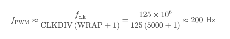
In our code, WRAPVAL=5000, CLKDIV=125, and fclk≈125 MHz, so the PWM frequency is about 200 Hz. The duty cycle is set by level/WRAPVAL. A larger level means a larger duty cycle and higher speed.
(2) Encoder pulse counting (for speed / distance estimation, extendable)
Each wheel has a photointerrupter that outputs pulses. PICO_A counts pulses using GPIO rising-edge interrupts.
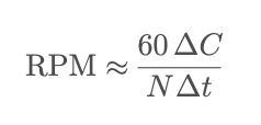
If the encoder has N pulses per revolution (PPR), and we measure a pulse increase ΔC within a time window Δt,
we can estimate wheel speed as:
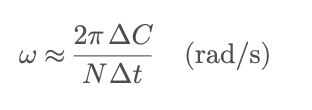
With wheel radius r, the linear speed can be estimated by:
The total pulse count can also be used to estimate distance. In this project, encoder counting is mainly used for debugging and future closed-loop control.
(3) Fixed-point (Q15) representation for UART packets
To transmit the scan angle with a stable and compact format, we encode the angle using Q15 fixed-point.
Q15 means we multiply a real value by 215 and store it as an integer. In our code we use float2fix15(x)=x×32768,
and on the receiver side we convert it back with fix2float15(x)=x/32768.
This avoids directly sending floats over UART and makes the packet format simple and consistent.
3. Logic Structure
Our system has two closed loops that run at the same time: a sensing uplink (LiDAR scan data to the host PC) and a control downlink (host PC commands to the robot). We split the work across two Pico W boards so that the real-time scan pipeline is not slowed down by Wi-Fi and UDP delays.
(1) Sensing uplink: TF-Luna → PICO_B → PICO_A → host PC
First, the TF-Luna LiDAR outputs a continuous UART byte stream. On PICO_B, Core 1 reads and parses the TF-Luna frames
and updates the latest distance value. In parallel, the stepper motor provides the scan angle reference.
We tie angle sampling to real step events (PIO-assisted stepping and interrupts), so each sample has a consistent
“angle + distance” pair. Then PICO_B packs the data into a compact UART packet (fixed header + angle field + distance field)
and sends the packet to PICO_A through UART0. On PICO_A, a small UART receive FSM finds the packet header, reads the payload,
reconstructs angle and distance, and sets a ready flag. Finally, PICO_A sends the decoded scan data to the host PC using Wi-Fi/UDP,
so the PC can display the real-time scan messages.
(2) Control downlink: host PC → PICO_A → motor driver → DC motors
The host PC provides a simple control panel in a web page. When the user presses a button (Forward/Back/Left/Right/Stop)
or changes the speed slider, the browser sends a short command through WebSocket. A Python UDP-WebSocket bridge on the host PC
receives the WebSocket message, converts it into a UDP command string, and sends it to PICO_A over the local network.
On PICO_A, the UDP receive callback parses the direction and speed, clamps the speed to a safe range, and updates shared command variables.
The motor control thread on the other core reads the updated command and outputs direction pins and PWM duty cycle to the motor driver (TB6612FNG),
which drives the two DC motors for motion execution.
(3) Concurrency and data consistency
To keep the system stable, we use clear producer-consumer handshakes between tasks.
On the sensing path, the scan producer and the network sender are separated by “ready” flags, so we do not send half-updated data.
On the control path, UDP command parsing and motor output are separated by an “update” flag, so motor output changes only when a new command arrives.
We also keep interrupt handlers short and use volatile shared variables for cross-core visibility. This structure lets us stream scan data
while still keeping motor control responsive.
4. Hardware/Software Trade-offs
(1) One Pico W vs. two Pico W boards (system partition)
At the beginning, we tried to use only one Pico W to do everything: stepper rotation, TF-Luna UART reading and parsing, Wi-Fi/UDP networking, and DC motor PWM output. After integration, we saw clear timing jitter because the Wi-Fi/UDP stack and memory operations can introduce unstable delays. However, UART parsing and motor control are real-time tasks and should not miss cycles. To improve stability, we moved to a two-board design. PICO_B focuses on scanning (stepper + TF-Luna + packet packing), and PICO_A focuses on networking and motion execution (UART receive + UDP forward + motor control). This makes the system more stable and easier to debug, but it adds extra wiring and one more UART link.
(2) Stepper angle timing: PIO interrupt (hardware-assisted) vs. main-loop timing (software)
For the scanning angle, we update the step counter and the sampling timing inside the PIO interrupt handler,
instead of using a software timer in the main loop. The key idea is to let PIO generate step events with stable timing,
and then let the CPU ISR update the step counter based on real hardware step events. In our design, each step event is
tied to the motor output sequence, so the angle update and the TF-Luna distance sample are more consistent in time.
This reduces drift caused by scheduling delays or Wi-Fi workload on the main loop.
The trade-off is higher code complexity. We must keep the ISR short and we must carefully manage shared variables
across interrupts and cores.
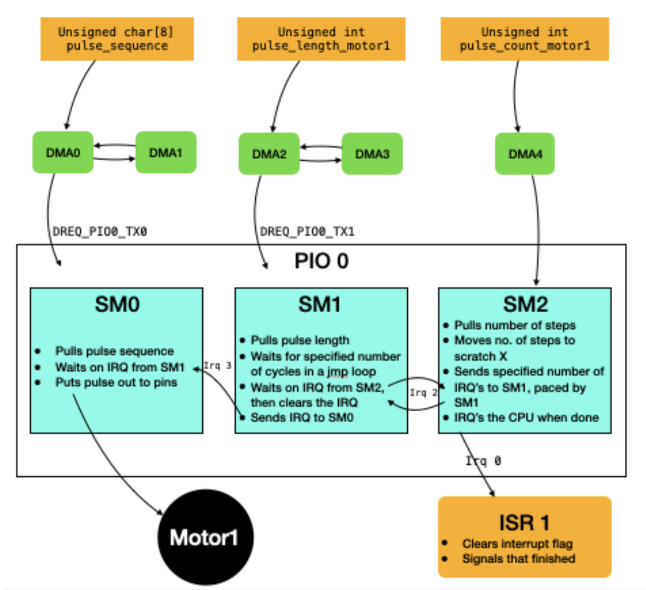
Figure 1. PIO + DMA stepper motor control architecture (adapted from V. Hunter Adams's RP2040 motor library). DMA streams the phase sequence and timing parameters into PIO state machines, and the CPU ISR is triggered by PIO step events for step counting.
In this hardware-assisted approach, the stepper phase pattern (pulse sequence) is streamed by DMA into the PIO TX FIFO. Another DMA stream provides the pacing value (pulse length) so the step timing stays stable. A third DMA stream provides the requested step count. Inside PIO, multiple state machines coordinate using IRQ signals to (1) output the 4-wire phase pattern, (2) wait the correct time between steps, and (3) count steps and raise an IRQ to the CPU. Our firmware uses this PIO IRQ to update the scan angle reliably. This is why we prefer PIO interrupts over a pure software timer in the main loop.
(3) Wheel encoder reading: GPIO interrupts vs. polling
We count wheel encoder pulses using GPIO rising-edge interrupts on PICO_A, rather than polling the encoder pins in a loop. Interrupt counting is more reliable for short pulses and does not waste CPU time when nothing happens. It also keeps the count accurate even when the network stack is busy. The trade-off is that interrupt-based code needs careful setup (pull-ups, edge selection) and shared counters should be handled safely (for example, using volatile variables).
(4) Angle representation for UART: float vs. Q15 fixed-point
For the UART packet between PICO_B and PICO_A, we encode the scan angle using Q15 fixed-point instead of sending a float directly. Fixed-point data has a stable and compact binary format, and it is easier to decode consistently on the receiver. This helps avoid problems with float formatting and keeps the packet size small. The trade-off is that we must convert between float and Q15 on both sides, so the code is slightly less direct.
(5) Data format to the host PC: binary packet vs. readable text
Inside the Pico-to-Pico link, we use a compact 8-byte binary packet for efficiency and simple framing. For the UDP messages sent to the host PC, we chose a readable text string (angle and distance) so that logging and web display are easier during debugging and demos. This choice makes development faster and the output more understandable. The trade-off is that text messages cost more bytes than binary, but the bandwidth is still enough for our update rate, so we accept this for better usability.
5. Intellectual Property Considerations (IP)
In the project, we mainly used the code framework and sample resources provided by the course, including the Pico W Wi-Fi/UDP (cyw43/lwIP) example provided by Professor V. Hunter Adams and the motor_library for stepper motor control (PIO + DMA drive idea), and also Cornell protothreads as a lightweight concurrent scheduling framework. Based on this, we independently completed system integration and functional development (such as dual Pico division architecture, UART data packet protocol, TF-Luna byte stream parsing state machine, UDP gateway and control panel, etc.). We did not directly copy or rely on the complete project code of a third party on GitHub. For the libraries and examples provided or referred to in the course, we will clearly indicate their sources and purposes in the web pages, and they will only be used for learning and course project display.
Hardware Design
The hardware of this project consists of multiple components: two Raspberry Pi Pico W as the core controllers, among which PICO_B is specifically responsible for rotation scanning and ranging acquisition, and PICO_A is responsible for network communication and trolley motion execution. The ranging part uses the TF-Luna LiDAR laser ranging module, which outputs millimeter-level distance data through UART for real-time perception of the distance of obstacles ahead. The scanning mechanism adopts a 28BYJ-48 stepper motor to provide stable angle stepping, and in combination with the ULN2003 stepper motor driver board, it realizes the amplification drive and phase sequence control of the stepper motor coil.
The sports chassis adopts two DC motors (left and right wheels) and a motor drive module. PICO_A outputs direction control signals and PWM speed signals to achieve forward, backward, left turn, right turn and speed adjustment. To obtain wheel motion feedback, a wheel photointerrupter is installed on each of the left and right wheels. The output pulse signals are connected to the GPIO interrupt of PICO_A for counting, which is used to record the number of wheel rotation pulses, which supporting speed and mileage estimation and debugging.
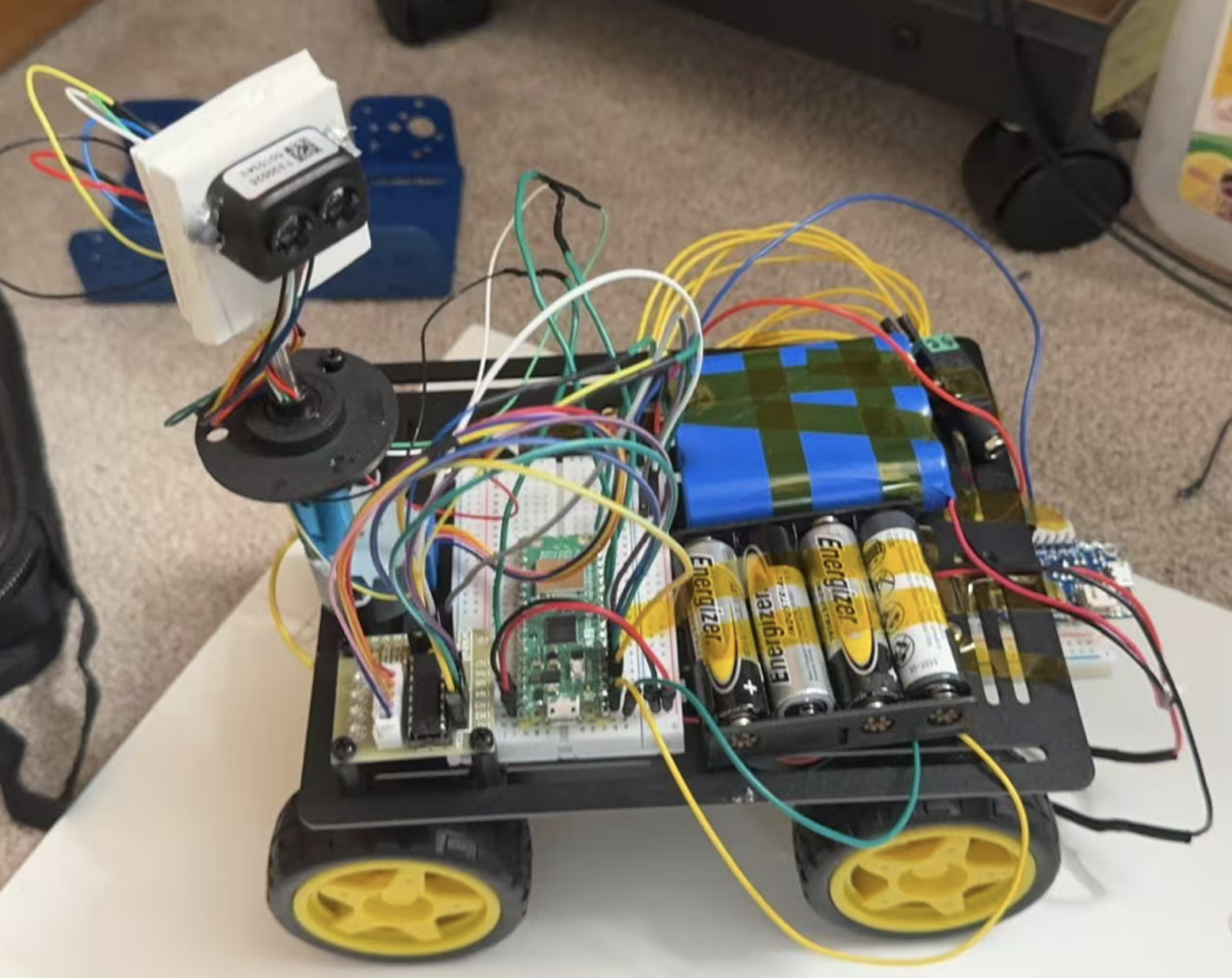
Figure 2. Hardware setup of our robot (Pico W controllers, LiDAR scanning module, motor driver, wheel encoders, and power supply). Note: the second Pico W (PICO_B) is mounted underneath the chassis base and is partially occluded in this photo.
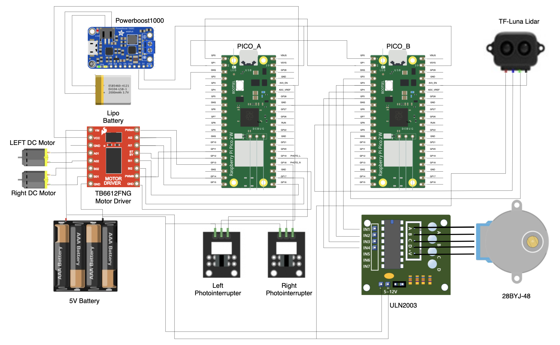
Figure 3. Hardware wiring diagram (PICO_A/PICO_B pin connections and module interfaces)
Parts List
- Microcontrollers: 2 × Raspberry Pi Pico W (PICO_A and PICO_B)
- Ranging & Scanning:
- 1 × TF-Luna LiDAR module (UART distance output)
- 1 × 28BYJ-48 stepper motor
- 1 × ULN2003 stepper motor driver board
- Chassis & Motion:
- 2 × DC motors (left / right wheels)
- 1 × Dual DC motor driver module
- 2 × Photointerrupters (wheel encoders)
- Communication:
- Wi-Fi (built-in on Pico W) for UDP communication with the host PC
- UART wiring between PICO_A and PICO_B
- Power & Wiring:
- 1 × LiPo battery (3.7V)
- 1 × PowerBoost 1000C (LiPo charger + 5V boost converter)
- Battery pack / external power supply (for motors and modules)
- Breadboard / jumper wires / connectors
- USB power (for Pico programming and debugging)
Software Design
1. Software Architecture Overview
Our software is split into two Pico W boards to keep the system stable and responsive. PICO_B is the “scanning sensor node”. It rotates a stepper motor for angle reference, reads TF-Luna distance data by UART, and sends compact “angle + distance” packets to PICO_A by another UART link. PICO_A is the “communication gateway and motion executor”. It receives LiDAR packets from PICO_B, then forwards them to the host personal computer by Wi-Fi/UDP. At the same time, PICO_A receives motion commands from the host PC by UDP and drives two DC motors. We use the RP2040 dual-core feature to run communication and control in parallel, so the network stack does not block real-time motor actions.
2. PICO_B (Stepper + TF-Luna + UART Packet Sender)
PICO_B builds a rotating scan-and-send subsystem. It drives the stepper motor to rotate continuously, and uses the motor steps as the angle reference. In parallel, it reads the TF-Luna distance stream over UART1 (GPIO8/9, 115200, 8N1). Core 1 runs the TF-Luna receive and parsing logic, while Core 0 runs stepper motor setup and packet sending. This split avoids blocking the main loop with UART parsing and keeps the scan timing consistent.
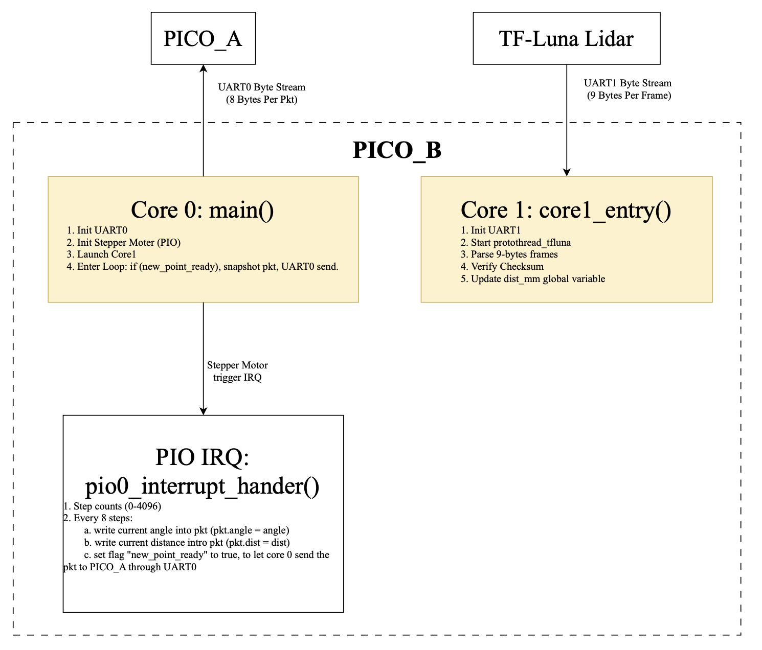
Figure 4. PICO_B software architecture (dual-core + PIO interrupt)
TF-Luna parsing is implemented as a byte-by-byte finite state machine (FSM). The thread waits until UART1 is readable, reads one byte each time, and searches for the frame header 0x59 0x59. After two header bytes are found, it collects the remaining bytes until a full 9-byte frame is received. Then it checks the checksum by summing the first 8 bytes and comparing with the last byte. Only valid frames update dist (in mm). The shared distance value is declared as volatile so Core 0 and the interrupt handler always see the latest value.
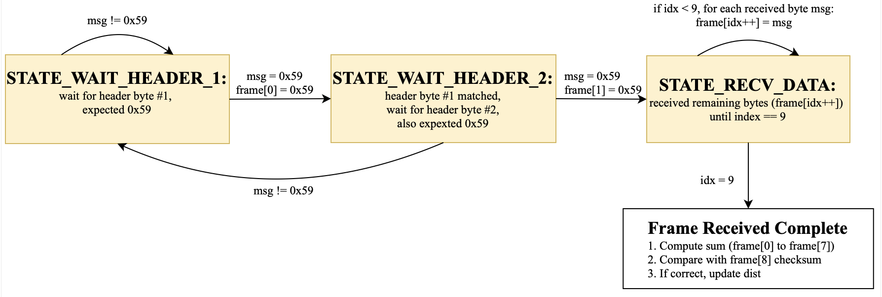
Figure 5. TF-Luna UART frame parsing FSM (0x59 0x59 + checksum)
The stepper motor angle sampling is maintained by a PIO interrupt. Every step interrupt increments step_count and wraps it at 4096 steps per full rotation (360°). To control bandwidth, we down-sample the scan and only create one point every 8 steps. At each sampling point, the interrupt converts step_count to an angle, stores it as a Q15 fixed-point value in pkt.angle, and copies the latest dist into pkt.dist_mm. It then sets new_point_ready=true. In the main loop, Core 0 checks this flag, clears it, copies the global pkt into a local snapshot, and sends the 8-byte packed lidar_pkt_t over UART to PICO_A.
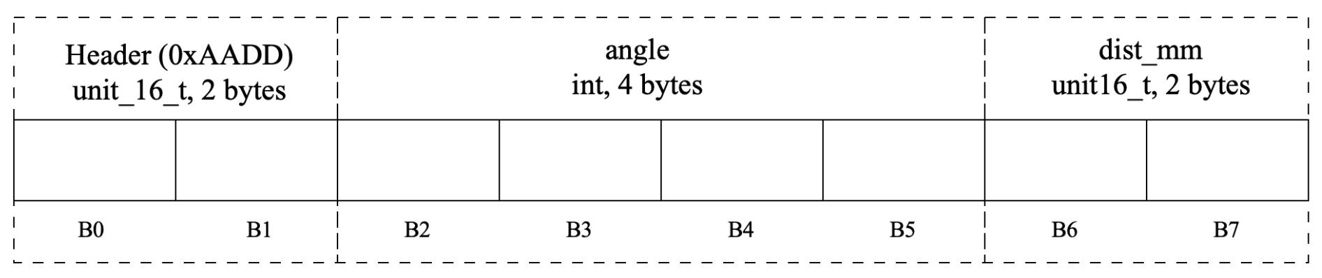
Figure 6. UART packet format from PICO_B to PICO_A (8 bytes: header + angle + distance)
Tricky parts on PICO_B include: (1) TF-Luna is a continuous byte stream, so frame sync and checksum are required to avoid wrong distance jumps. (2) concurrency exists between Core 1 (dist update), the interrupt (pkt update), and Core 0 (pkt send), so we use volatile variables and a local snapshot before sending. (3) sampling every 8 steps is a tradeoff between angle resolution and UART bandwidth, and Q15 fixed-point avoids float format issues across UART.
3. PICO_A (UDP Gateway + UART Receiver + DC Motor Control)
PICO_A works as the network gateway and the motion executor. It receives LiDAR packets from PICO_B via UART0 and forwards the data to the host PC via Wi-Fi/UDP. At the same time, it receives motion commands from the host PC by UDP and drives two DC motors. We use dual cores so that networking and control can run in parallel.
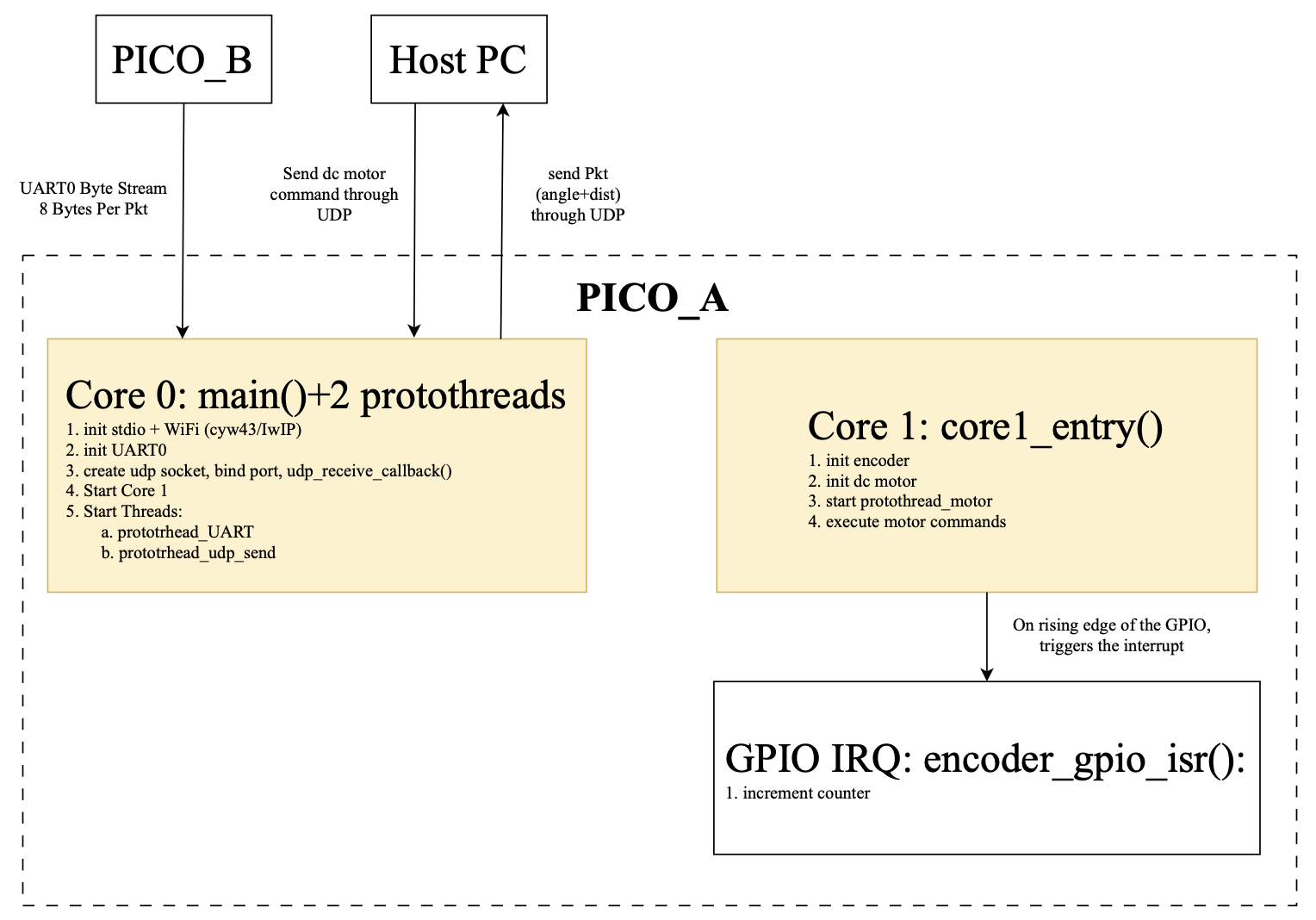
Figure 7. PICO_A software architecture (dual-core: UART/UDP data path + motor control + encoder IRQ)
Core 0 handles the data path and networking. It runs two protothreads: protothread_UART and protothread_udp_send. protothread_UART reads UART0 one byte at a time and feeds bytes into uart_rx(byte). uart_rx is a small FSM that looks for the header 0xAADD and then reads 6 payload bytes. After a full packet is decoded, it fills pkt.angle and pkt.dist_mm and sets pkt_ready=true. protothread_udp_send waits for pkt_ready, converts angle from Q15 to float, formats a short text message, and sends it to the host PC using udp_sendto. UDP control commands are received by udp_receive_callback (a lwIP callback). It parses commands like “F 3000” or “S”, clamps speed, and updates motor_cmd_dir and motor_cmd_speed, then sets motor_cmd_update=true for the motor thread.
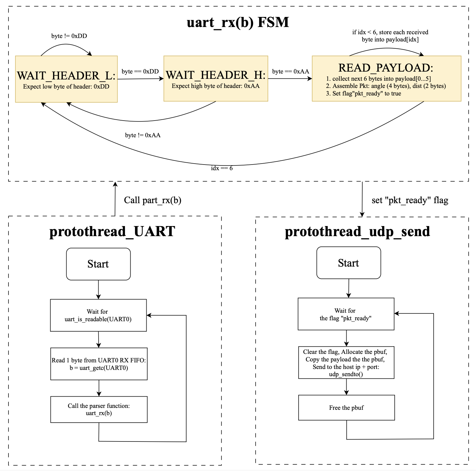
Figure 8. PICO_A UART to Parser FSM to UDP send workflow (protothreads + pkt_ready handshake)
Core 1 focuses on real-time motor control and encoder counting. It initializes the two photointerrupter pins as inputs with pull-ups and enables rising-edge IRQ. The ISR increments the left or right encoder counter. It also initializes the motor driver pins and PWM channels (wrap and clkdiv set the PWM frequency, and duty starts from zero). Then it runs protothread_motor, which waits for motor_cmd_update and executes the command by setting direction pins and PWM duty. This makes motor output responsive even when Core 0 is busy with Wi-Fi and UDP.
Tricky parts on PICO_A include: (1) UART and UDP are both asynchronous sources, so we use clear producer-consumer flags (pkt_ready and motor_cmd_update) to avoid half packets or repeated actions. (2) the Pico W network stack requires protected access, so we send UDP inside cyw43_arch_lwip_begin/end and manage pbuf correctly. (3) shared variables across cores use volatile, and we clear flags early and use stable parsing order to reduce race risks.
4. User Interface
We designed index.html as the control and monitoring interface running on the Host PC, with the goal of making the entire human-computer interaction as simple and intuitive as possible. The UDP Message Log at the top of the page uses a read-only textarea to display the system log in real time: It connects to the locally running Python UDP-WebSocket bridge via WebSocket (ws://localhost:8765). As long as UDP data (such as text with forwarded angle/distance information) arrives at the Pico end, bridge will push the message to the web page and append it to the log box. The front end will also automatically determine whether it is currently at the bottom of the log. If so, it will automatically scroll to ensure that the latest messages can always be seen even during long-term operation.
The Control Panel is at the bottom of the page. The four direction buttons (F/L/R/B) support "hold for continuous sending" : After the mouse is pressed or touched to start, the page will send a control command for "direction + speed" every 100 ms. Immediately send "S" as the stop command after release. The speed slider on the right is used to adjust the speed parameters in real time. When it is slid, the displayed value will be updated immediately, and the speed of transmission will be dynamically affected during the process of holding and moving.
We further integrated TinySLAM to achieve online mapping and pose estimation visualization based on real-time LiDAR scanning. The map area in the center of the interface will continuously refresh to display occupancy points and the robot's movement trajectory. While remotely controlling the vehicle, the operator can intuitively see the environmental structure and driving path.
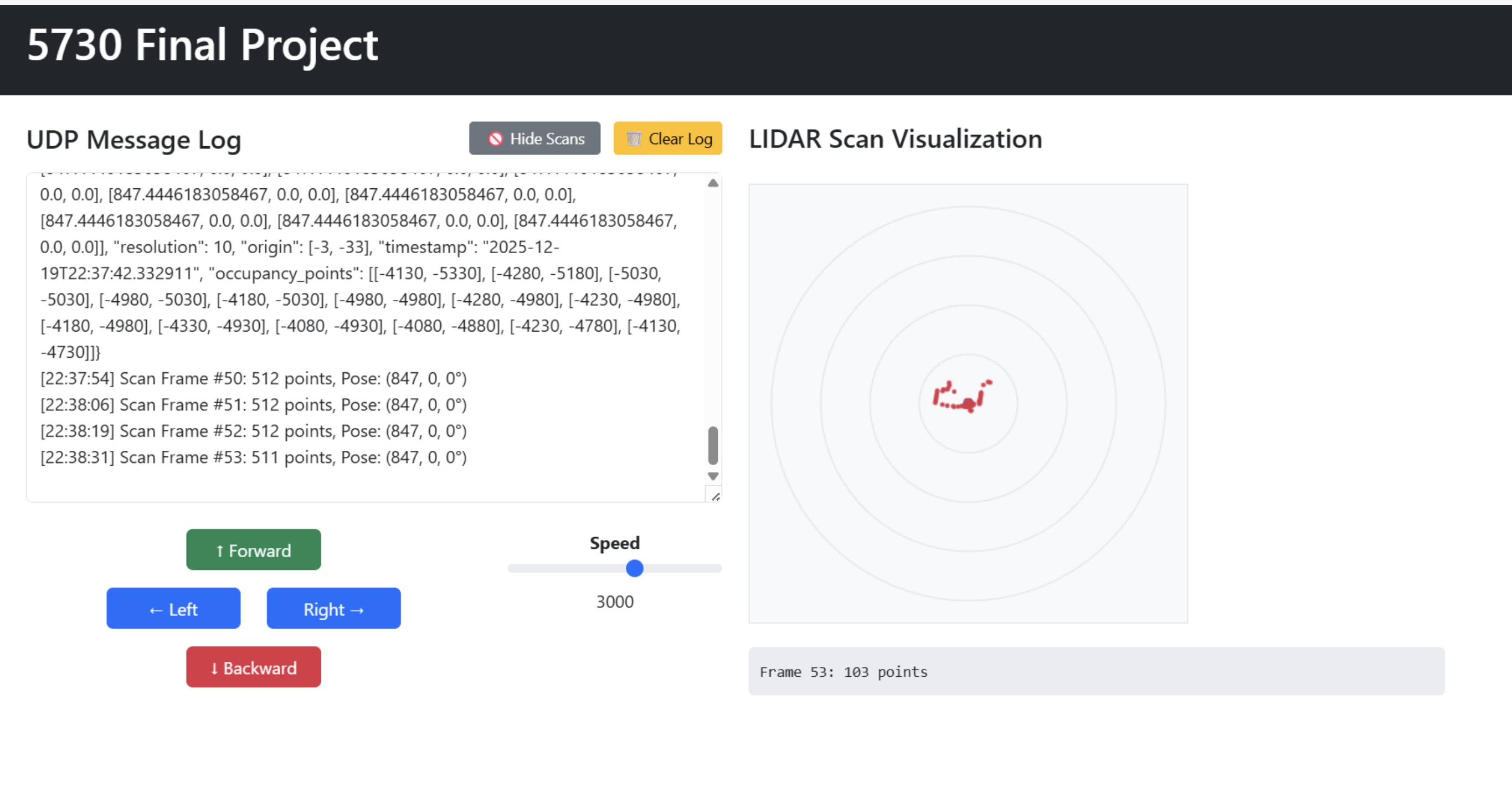
Figure 9. Original Host PC web control UI (UDP message log + directional buttons + speed slider + LiDAR scan plot).
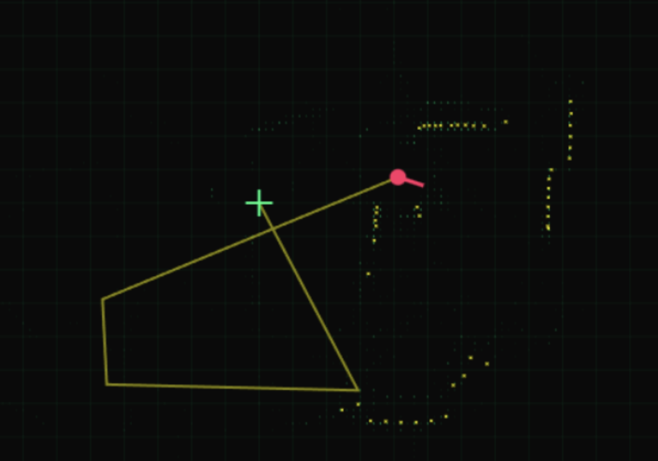
Figure 10. TinySLAM mapping visualization (robot trajectory and occupancy points built from LiDAR scans).
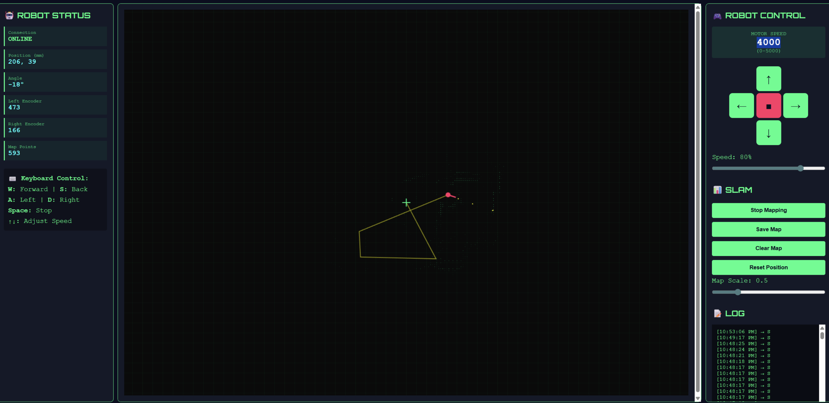
Figure 11. Integrated dashboard for teleoperation and mapping (robot status + SLAM map + control panel + logs).
5. Things we tried which did not work
The first pitfall we fell into was wanting to do everything with just one Pico W: The same board not only needs to drive the stepper motor to rotate continuously (and also needs to perform timed/interrupted sampling angles), but also needs to use UART to read the byte stream of TF-Luna at high speed and perform frame parsing, and at the same time run Wi-Fi/UDP (receive control from the personal computer and send radar data), and then output PWM and direction in real time to control the dual DC motors. During the actual integration, we found that the Wi-Fi/UDP link would bring obvious real-time jitter: operations such as network stack processing, pbuf allocation, callback triggering, and critical section protection for lwIP would cause unstable delays in the main loop/thread scheduling. However, UART parsing and motor control are tasks that cannot be missed. Once the scheduling is interrupted by the network side, it is easy to have phenomena such as discontinuous serial port reception and frequent resynchronization of the parsing state machine. To decouple "real-time sampling/parsing" and "network communication and forwarding", we ultimately adopted a dual Pico architecture. PICO_B is dedicated to the scanning end (stepper motor + TF-Luna parsing, and the Angle + distance is packaged and sent out through UART), while PICO_A is dedicated to the gateway and execution end (UART receiving packets, then parsing, UDP reporting, and simultaneously UDP sending control command to drive the motor). After that, the overall stability of the system is significantly improved.
The second attempt but with unsatisfactory results was to use Pico W as an Access Point (AP) to connect the computer to its Wi-Fi. At first, we hoped that Pico would set up its own hotspot and the PC would directly connect to it for communication, so that we wouldn't have to rely on the existing router or personal hotspot. However, in actual use, it was found that the AP mode was not cost-effective in our scenario: after the computer was connected to the Pico hotspot, the network configuration (IP allocation/routing /DNS, etc.) was more prone to problems, and the debugging cost was high. More importantly, the AP mode will cause Pico to bear the additional cost of maintaining hotspots and managing connections, while our system is also performing tasks such as UART receiving and parsing, UDP sending, and motor control. As a result, the connection is not stable enough, the throughput and latency fluctuates more significantly, and the overall experience actually deteriorates.
6. Thorough discussion of AI use
We didn't use any AI to generate our code, we use AI to assist with debugging. When integrating the PIO stepper motor solution provided by professor, the stepper motor may exhibit phenomena such as "not rotating/shaking/stopping after a few rotations". We suspect that the problem stems from the handshake signals between the PIO state machines (the three state machines of pacer, stepper, and counter cooperate through IRQ). We send the phenomenon description and key PIO fragments to the AI and ask it to help us check if the logic is self-consistent. For example, in stepp.pio, wait 1 irq 3 should be used to wait for the pacer to be triggered instead of instructions like set that merely output the level on the pin. In addition, in counter.pio, the meaning of irq wait 2 is "wait for the CPU to clear the corresponding flag before continuing to execute". If the CPU side fails to clear it in time or the IRQ numbers are inconsistent, it may cause the state machine to freeze. AI has provided us with a checklist for troubleshooting, including: Confirm whether each IRQ number is consistent, whether it is triggered on the correct state machine, whether the CPU interrupt handling function has cleared the corresponding PIO interrupt flag, and whether the DMA is continuously feeding data to the TX FIFO of the PIO. We checked the code item by item according to these checkpoints and finally located that it was we who wrote the waiting condition of IRQ wrongly during the modification, resulting in the stepper state machine not pacing as expected and thus causing the exception. After the correction, the stepper motor resumed stable continuous rotation. In addition, AI also helps us understand some hardware datasheets more quickly (such as the communication frame format of TF-Luna, the meanings of key registers/parameters, and the PWM/ PIO-related explanations of RP2040), thereby reducing the cost of understanding when looking up information.
Results
In the final system, the web control panel of the Host PC supports clicking the button to continuously send F/L/R/B/S instructions. PICO_A can respond to the motor within approximately 0.1-0.2 seconds, with almost no obvious delay subjectively. Meanwhile, PICO_B will continuously drive the stepper motor to rotate and complete the scanning, and constantly collect the distance data of TF-Luna, and package the "Angle + distance" and send it to PICO_A via UART; PICO_A can continuously receive UART data packets and forward them to the Host PC via UDP, so the web page can continuously refresh to display angle and dist information.
We let the system run continuously for about 2 minutes. The data on the web page shows continuous updates, and the control commands can also take effect continuously. No obvious lag or packet loss caused long-term interruption was observed. In terms of concurrency, even if UDP continuously reports LiDAR data, the DC motor control can still maintain a timely response. This is because we have adopted dual-core splitting, protothreads scheduling, and UDP callback coupling in the software structure, separating network processing with uncertain delays from real-time control tasks, thereby reducing the blocking of the network stack on motor control and serial port reception parsing.
In terms of accuracy, the ranging error of TF-Luna is within a reasonable range in our indoor tests (for example, within the range of 0.5-1.5 m, the reading usually differs from the actual distance by a few centimeters (about ±3-5 cm)), and the angular resolution is determined by the number of steps of the stepper motor: 4096 steps = 360°, with sampling conducted every 8 steps. Therefore, the angular resolution is approximately 360/4096×8 ≈ 0.703°. The wheel speed encoder (photointerrupter) is currently mainly used for counting and debugging verification. The counting of the left and right wheels may be somewhat inconsistent due to friction, tire slippage or motor differences.
If you want to reproduce this project, you need to prepare two Raspberry Pi Pico W (respectively as PICO_A and PICO_B), a TF-Luna LiDAR, a 28BYJ-48 stepper motor, a ULN2003 driver board, a TB6612FNG motor driver module, two DC motor (left and right wheels), two photointerrupter/wheel encoders (wheel speed pulse input), and a personal computer serving as the Host PC.
The reproduction steps are as follows: First, turn on the mobile phone's hotspot or router and ensure that the Pico is on the same network as the computer. Set HOST_IP to the local IP of the computer in the Pico code; Run the UDP-WebSocket bridge program of Python on the computer end; Then open the HTML control page with a browser; When the prompt "Pico connected" appears in the web page, you can control the movement of the car through the web page button and continuously see the angle and distance data of the LiDAR being transmitted back.
Conclusions
If we do it again, we will add two more practical functional improvements on the basis of the existing "Visual Remote control" system. The first is to add a simple "obstacle avoidance assistance mode" : When TF-Luna detects that the distance ahead is too close, the system will automatically slow down the "forward" command or force a stop directly in more dangerous situations, thereby providing a layer of safety protection when the operator fails to react in time or makes a mistake in operation, and truly transforming the visual feedback of "Angle + Distance" into more reliable driving decision support.
The second is to upgrade the current open-loop speed control that mainly relies on PWM duty cycle to a lightweight closed-loop speed regulation: Due to factors such as ground friction changes and differences between the left and right motors, the same PWM setting does not always correspond to the consistent actual wheel speed. Next, we plan to use the left and right wheel encoders for speed estimation and implement a simplified closed-loop control (for example, only using proportional control P) to fine-tune the left and right wheel PWM in real time, making the same SPEED command correspond more stably.
During the implementation process, we have endeavored to follow the "reproducibility, intercommunication and maintainability" norms in the course and engineering. In terms of interface and communication, the system adopts clear module boundaries: PICO_B to PICO_A uses UART serial port to transmit fixed-length data packets (with packet headers for frame synchronization), and PICO_A to Host PC uses Wi-Fi/UDP for control instructions and status return; The Host PC side converts the web page interaction into a stable UDP instruction format (such as "F 3000", "S") through Python UDP-WebSocket bridge to ensure that the communication protocol is simple, consistent and easy to debug.
In terms of electrical and engineering specifications, we use standard motor drive modules (stepper drive ULN2003, DC motor drive TB6612FNG) to complete motor power amplification and isolation control. The Pico side only outputs logic control signals and PWM, avoiding the overcurrent risk caused by directly driving the motor with GPIO. At the same time, the blocking of the network stack on the real-time control link is reduced through dual-core splitting, protothreads and callback mechanisms to meet the requirements of the course for real-time performance and system stability.
In terms of intellectual property (IP), this project mainly reuses the basic codes and libraries provided by the course, including the Wi-Fi/UDP connection framework provided by Professor V. Hunter Adams and the Cornell protothreads framework. And the PIO and DMA stepper motor control motor_library provided by the course (and indicate the source in the report and code).
In addition to the above-mentioned course resources, we have not used or copied any third-party GitHub project codes, nor have we used commercial ips with restricted licenses. Our system does not involve reverse engineering of existing products or closed designs, nor does it use any other person's trademark for promotion or product description. We have not signed an NDA for obtaining sample devices either. As this project mainly focuses on the engineering integration and stability verification of the common "remote control + sensor return transmission" robot system in the course, the overall solution is a combination implementation of mature ideas. Currently, we do not believe that it has innovative points that can be independently patented.
Work Distribution
Qishun Zhang (qz426)
Implemented TF-Luna UART parsing, stepper scanning module, integrated and debugged the whole system, and designed the top-level software and hardware architecture.
Zhe Tong (zt286)
Built the DC motor control and stepper motor support, wrote the webpage, worked on the whole hardware design and wiring, and helped write the project website.
Dina Shi (ds2489)
Debugged the stepper motor and DC motor driving code, wrote the host PC control webpage, integrated the whole system, and contributed to the website writing.
Appendix
Appendix A: Permissions
The group approve this report for inclusion on the course website.
The group approve the video for inclusion on the course youtube channel.
Appendix B: References
Cornell ECE Final Projects Archive (previous years)
RP2040 Datasheet (Raspberry Pi)
Raspberry Pi Pico Pinout (PDF)
Raspberry Pi Pico SDK Documentation (Doxygen)
Raspberry Pi Pico / Pico W Documentation (Pico Series)
lwIP TCP/IP Stack Documentation
Python websockets Library Documentation
Bootstrap Documentation
TF-Luna LiDAR Product Manual (PDF)
28BYJ-48 Stepper Motor Datasheet (PDF, Mouser)
ULN2003A Darlington Driver Datasheet (Texas Instruments)
TB6612FNG Motor Driver Hookup Guide (includes datasheet references)
MakersPortal: Distance Detection with TF-Luna LiDAR and Raspberry Pi
Appendix C: Code Listings
Full source code repository (maintained by our teammate): https://github.com/shunshun213/5730-Final_Project
// PICO_A.c
/* ---------------------------------------------------------------------------------------------- */
/*                PICO A Function: UDP + UART + DC_Motor Control + Photointerrupter               */
/* ---------------------------------------------------------------------------------------------- */
#include
#include "string.h"
#include "pico/stdlib.h"
#include "pico/cyw43_arch.h"
#include "lwip/pbuf.h"
#include "lwip/udp.h"
#include "lwip/netif.h"
#include "hardware/uart.h"
#include "UART.h"
#include "pt_cornell_rp2040_v1_4.h"
#include "Connection.h"
#include "hardware/pwm.h"
#include "pico/multicore.h"

/* ---------------------------------------------------------------------------------------------- */
/*                                            Fix Point                                           */
/* ---------------------------------------------------------------------------------------------- */
typedef signed int fix15 ;
#define float2fix15(a) ((fix15)((a)*32768.0)) // 2^15
#define fix2float15(a) ((float)(a)/32768.0)
#define int2fix15(a) ((fix15)(a << 15))
#define fix2int15(a) ((int)(a >> 15))

/* ------------------------------------------- macros ------------------------------------------- */
#define PICO_UART_ID    uart0   //uart channel for connection with PICO B
#define BAUD_RATE       115200  //Baud Rate for UART communication

#define UART_TX_PIN     0       //UART TX PIN
#define UART_RX_PIN     1       //UART RX PIN

#define HOST_IP         "172.20.6.246"    // Host computer's IP
#define UDP_PORT        8888              // Port for pico - host computer communication

#define MOTOR1_IN1      15  // AI1
#define MOTOR1_IN2      14  // AI2
#define MOTOR1_PWM      13  // PWMA

#define MOTOR2_IN1      16  // BI1
#define MOTOR2_IN2      17  // BI2
#define MOTOR2_PWM      11  // PWMB

#define STANDBY         12  // Standby

#define PHOTO_L         19  // Left PhotoInterrupter
#define PHOTO_R         18  // Right PhotoInterrupter

#define WRAPVAL 5000    //Wrap Value for PWM Counter
#define CLKDIV  125     //Clock Divier to get a 200Hz PWM Frequency

#define abs(x) ((x < 0) ? -x : x)
#define debug_printf(x, y) printf(x, y)

/* -------------------------------------- Global Variables -------------------------------------- */
ip_addr_t       dest_addr;  //ip address of host computer
struct udp_pcb *udp_socket; // UDP socket

volatile uint16_t l_encoder_counter = 0; //Counter for left encoder
volatile uint16_t r_encoder_counter = 0; //Counter for right encoder

uint slice_num_A; //pwm slice number for left motor PWM
uint channel_num_A; //Channel numner for left motor PWM
uint slice_num_B; //pwm slice number for right motor PWM
uint channel_num_B; //Channel numner for right motor PWM

lidar_pkt_t pkt; //data packet receive from PICO B via UART
volatile bool pkt_ready = false; //whether the data packet is being completely received

volatile int motor_cmd_speed = 0;   // 0 - 5000
volatile char motor_cmd_dir = 'S';  // F B L R S
volatile bool motor_cmd_update = false;
/* ---------------------------------------------------------------------------------------------- */
/*                       Interrupt Service Routine for photointerrupter Pins                      */
/* ---------------------------------------------------------------------------------------------- */
void encoder_gpio_isr(uint gpio, uint32_t events){
    if(events & GPIO_IRQ_EDGE_RISE){
        if(gpio == PHOTO_L){
            l_encoder_counter++;
        }
        else if(gpio == PHOTO_R){
            r_encoder_counter++;
        }
    }
}

/* ---------------------------------------------------------------------------------------------- */
/*                                    Initialization Functions                                    */
/* ---------------------------------------------------------------------------------------------- */

/* --------------------- Photointerrupter/encoder Pin Initilization with IRQ -------------------- */
void encoder_init(){
    gpio_init(PHOTO_L);
    gpio_set_dir(PHOTO_L, GPIO_IN);
    gpio_pull_up(PHOTO_L);

    gpio_init(PHOTO_R);
    gpio_set_dir(PHOTO_R, GPIO_IN);
    gpio_pull_up(PHOTO_R);

    gpio_set_irq_enabled_with_callback(
        PHOTO_L,
        GPIO_IRQ_EDGE_RISE,
        true,
        &encoder_gpio_isr
    );

    gpio_set_irq_enabled(
        PHOTO_R,
        GPIO_IRQ_EDGE_RISE,
        true
    );
}

/* --------------------------- DC Motor and PWM Channel Initialization -------------------------- */
void dc_motor_init(){
    gpio_init(MOTOR1_IN1);
    gpio_init(MOTOR1_IN2);
    gpio_set_dir(MOTOR1_IN1, GPIO_OUT);
    gpio_set_dir(MOTOR1_IN2, GPIO_OUT);

    gpio_init(MOTOR2_IN1);
    gpio_init(MOTOR2_IN2);
    gpio_set_dir(MOTOR2_IN1, GPIO_OUT);
    gpio_set_dir(MOTOR2_IN2, GPIO_OUT);

    gpio_init(STANDBY);
    gpio_set_dir(STANDBY, GPIO_OUT);
    gpio_put(STANDBY, 1);

    gpio_init(MOTOR1_PWM);
    gpio_set_function(MOTOR1_PWM, GPIO_FUNC_PWM);
    slice_num_A = pwm_gpio_to_slice_num(MOTOR1_PWM);
    channel_num_A  = pwm_gpio_to_channel(MOTOR1_PWM);

    pwm_set_wrap(slice_num_A, WRAPVAL);
    pwm_set_clkdiv(slice_num_A, CLKDIV);
    pwm_set_chan_level(slice_num_A, channel_num_A, 0);
    pwm_set_enabled(slice_num_A, true);

    gpio_init(MOTOR2_PWM);
    gpio_set_function(MOTOR2_PWM, GPIO_FUNC_PWM);
    slice_num_B = pwm_gpio_to_slice_num(MOTOR2_PWM);
    channel_num_B  = pwm_gpio_to_channel(MOTOR2_PWM);

    pwm_set_wrap(slice_num_B, WRAPVAL);
    pwm_set_clkdiv(slice_num_B, CLKDIV);
    pwm_set_chan_level(slice_num_B, channel_num_B, 0);
    pwm_set_enabled(slice_num_B, true);
}

/* ---------------------------------------------------------------------------------------------- */
/*                                   DC Motor Control Functions                                   */
/* ---------------------------------------------------------------------------------------------- */
void dc_motor_set(int speed) {
    if (speed > 0) {
        gpio_put(MOTOR1_IN1, 1);
        gpio_put(MOTOR1_IN2, 0);
        gpio_put(MOTOR2_IN1, 0);
        gpio_put(MOTOR2_IN2, 1);
    }
    else if (speed < 0) {
        gpio_put(MOTOR1_IN1, 0);
        gpio_put(MOTOR1_IN2, 1);
        gpio_put(MOTOR2_IN1, 1);
        gpio_put(MOTOR2_IN2, 0);
    }
    else {
        gpio_put(MOTOR1_IN1, 0);
        gpio_put(MOTOR1_IN2, 0);
        gpio_put(MOTOR2_IN1, 0);
        gpio_put(MOTOR2_IN2, 0);
    }
    pwm_set_chan_level(slice_num_A, channel_num_A, abs(speed));
    pwm_set_chan_level(slice_num_B, channel_num_B, abs(speed));

    printf("Motor Running");
}

void dc_motor_stop() {
    gpio_put(MOTOR1_IN1, 0);
    gpio_put(MOTOR1_IN2, 0);
    gpio_put(MOTOR2_IN1, 0);
    gpio_put(MOTOR2_IN2, 0);
    pwm_set_chan_level(slice_num_A, channel_num_A, 0);
    pwm_set_chan_level(slice_num_B, channel_num_B, 0);
}

void dc_motor_left(int speed) {
    gpio_put(MOTOR1_IN1, 1);
    gpio_put(MOTOR1_IN2, 0);
    gpio_put(MOTOR2_IN1, 1);
    gpio_put(MOTOR2_IN2, 0);
    pwm_set_chan_level(slice_num_A, channel_num_A, speed);
    pwm_set_chan_level(slice_num_B, channel_num_B, speed);
}

void dc_motor_right(int speed){
    gpio_put(MOTOR1_IN1, 0);
    gpio_put(MOTOR1_IN2, 1);
    gpio_put(MOTOR2_IN1, 0);
    gpio_put(MOTOR2_IN2, 1);
    pwm_set_chan_level(slice_num_A, channel_num_A, speed);
    pwm_set_chan_level(slice_num_B, channel_num_B, speed);
}
/* ---------------------------------------------------------------------------------------------- */
/*                                  UDP Receive Callback Function                                 */
/* ---------------------------------------------------------------------------------------------- */
void udp_receive_callback(void *arg, struct udp_pcb *pcb, struct pbuf *p, const ip_addr_t *addr, uint16_t port){
    if(!p) return;

    /* ----------------------------- Copy Payload from Received Message ----------------------------- */
    char buf[64];
    int len = p->len < 63 ? p->len : 63;
    memcpy(buf, p->payload, len);
    buf[len] = '\0';

    /* ---------------------------------------- Parse Command --------------------------------------- */
    char dir;
    int speed;

    if(buf[0] == 'S'){
        motor_cmd_dir = 'S';
        motor_cmd_speed = 0;
        motor_cmd_update = true;
    }
    else if(sscanf(buf, "%c %d", &dir, &speed) == 2){
        if(speed < 0) speed = 0;
        if(speed > WRAPVAL) speed = WRAPVAL;

        motor_cmd_dir = dir;
        motor_cmd_speed = speed;
        motor_cmd_update = true;
    }

    //printf("UDP RX: %s\n", buf);

    pbuf_free(p);
}

/* ---------------------------------------------------------------------------------------------- */
/*                                         UART RX Thread                                         */
/* ---------------------------------------------------------------------------------------------- */
static PT_THREAD(protothread_UART(struct pt *pt)){ //Thread for reading UART Message from
    PT_BEGIN(pt);
    while(true){
        PT_YIELD_UNTIL(pt, uart_is_readable(PICO_UART_ID));
        uint8_t b = uart_getc(PICO_UART_ID); //get a byte each time
        uart_rx(b);
    }
    PT_END(pt);
}

/* ---------------------------------------------------------------------------------------------- */
/*                                     UDP send packet Thread                                     */
/* ---------------------------------------------------------------------------------------------- */
static PT_THREAD(protothread_udp_send(struct pt *pt)){//udp messages
    PT_BEGIN(pt);
    char message[100];

    while(true){
        PT_YIELD_UNTIL(pt, pkt_ready);
        pkt_ready = false;
        float angle = fix2float15(pkt.angle);

        sprintf(message, "RX pkt: angle=%.3f dist=%u",
               angle, pkt.dist_mm);

        // Send message
        cyw43_arch_lwip_begin();
        struct pbuf *p = pbuf_alloc(PBUF_TRANSPORT, strlen(message), PBUF_RAM);
        if (p) {
            memcpy(p->payload, message, strlen(message));
            udp_sendto(udp_socket, p, &dest_addr, UDP_PORT);
            //printf("Sent: %s\n", message);
            pbuf_free(p);
        }
        cyw43_arch_lwip_end();
    }
    PT_END(pt);
}

/* ############################################################################################## */
/*                                         Control Thread                                         */
/* ---------------------------------------------------------------------------------------------- */
static PT_THREAD(protothread_motor(struct pt *pt)){
    PT_BEGIN(pt);
        while(true){
            PT_YIELD_UNTIL(pt, motor_cmd_update);

            motor_cmd_update = false;
            switch(motor_cmd_dir){
                case 'F':
                    dc_motor_set(motor_cmd_speed);
                    break;
                case 'B':
                    dc_motor_set(-motor_cmd_speed);
                    break;
                case 'L':
                    dc_motor_left(motor_cmd_speed);
                    break;
                case 'R':
                    dc_motor_right(motor_cmd_speed);
                    break;

                case 'S':
                default:
                    dc_motor_stop();
                    break;
            }

        }
    PT_END(pt);
}

void core1_entry(){
    /* -------------------------- Phtorointerrupter Encoder Initialization -------------------------- */
    encoder_init();
    dc_motor_init();
    pt_add_thread(protothread_motor);
    pt_schedule_start;
}


int main()
{
    stdio_init_all();

    /* ------------------------------------- wifi initialization ------------------------------------ */
    wifi_init(); //function in Connection.h

    /* ------------------------------------- UART initialization ------------------------------------ */
    UART_init(UART_TX_PIN, UART_RX_PIN, PICO_UART_ID, BAUD_RATE); //function in UART.h

    /* ----------------------------------------- UDP socket ----------------------------------------- */
    udp_socket = udp_new();
    if(!udp_socket){
        cyw43_arch_lwip_end();
        printf("Failed to create socket\n");
        return -1;
    }
    udp_bind(udp_socket, IP_ADDR_ANY, UDP_PORT);
    udp_recv(udp_socket, udp_receive_callback, NULL);

    printf("UDP ready on port %d\n", UDP_PORT);
    printf("Sending to %s:%d\n\n", HOST_IP, UDP_PORT);

    /* ------------------------------------ Add host computer IP ------------------------------------ */
    ip4addr_aton(HOST_IP, &dest_addr);

    // start core 1
    multicore_reset_core1();
    multicore_launch_core1(core1_entry);

    pt_add_thread(protothread_UART);
    pt_add_thread(protothread_udp_send);
    pt_schedule_start;

}

// PICO_B.c
/* ---------------------------------------------------------------------------------------------- */
/*                 PICO B Function: Stepper Motor + Lidar + UART datapacket sender                */
/* ---------------------------------------------------------------------------------------------- */

#include
#include
#include "pico/stdlib.h"
#include "hardware/uart.h"
#include "hardware/gpio.h"
#include "pico/multicore.h"
#include "pt_cornell_rp2040_v1_4.h"
#include "motor_library.h"


/* ---------------------------------------------------------------------------------------------- */
/*                                            Fix Point                                           */
/* ---------------------------------------------------------------------------------------------- */
typedef signed int fix15 ;
#define float2fix15(a) ((fix15)((a)*32768.0)) // 2^15
#define fix2float15(a) ((float)(a)/32768.0)
#define int2fix15(a) ((fix15)(a << 15))
#define fix2int15(a) ((int)(a >> 15))

/* ---------------------------------------------------------------------------------------------- */
/*                           PICO_A - PICO_B UART Communication Channel                           */
/* ---------------------------------------------------------------------------------------------- */
#define P_UART_ID       uart0
#define BAUD_RATE       115200
#define P_UART_TX_PIN   0
#define P_UART_RX_PIN   1

/* ---------------------------------------------------------------------------------------------- */
/*                                      TF-LUNA UART Channel                                      */
/* ---------------------------------------------------------------------------------------------- */
#define TF_UART_ID      uart1
#define L_UART_TX_PIN   8
#define L_UART_RX_PIN   9

/* ------------------------------------ TF-LUNA message frame ----------------------------------- */
#define TF_FRAME_LEN    9
typedef enum { STATE_WAIT_HEADER1, STATE_WAIT_HEADER2, STATE_RECV_DATA } tf_state_t;

volatile uint16_t dist = 0;
volatile uint16_t strength = 0;

/* ---------------------------------------------------------------------------------------------- */
/*                                        Stepper Motor Pin                                       */
/* ---------------------------------------------------------------------------------------------- */
#define STEPPER_IN1     2
volatile int    step_count = 0;
volatile float  step_angle = 0;
volatile bool   new_point_ready = false; //if a new angle or sampling point is reached

/* ------------------------------------- Packed UART message ------------------------------------ */
typedef struct __attribute__((packed)){
    uint16_t header;
    int angle;
    uint16_t dist_mm;
} lidar_pkt_t;

#define MSG_HEADER 0xAADD
lidar_pkt_t pkt;

/* ---------------------------------------------------------------------------------------------- */
/*                                       TF-Luna Read Thread                                      */
/* ---------------------------------------------------------------------------------------------- */
static PT_THREAD(protothread_tfluna(struct pt *pt))
{
    PT_BEGIN(pt);

    static uint8_t frame[TF_FRAME_LEN];
    static tf_state_t state = STATE_WAIT_HEADER1;
    static int idx = 0;

    while(true){
        PT_YIELD_UNTIL(pt, uart_is_readable(TF_UART_ID));
        uint8_t msg = uart_getc(TF_UART_ID);

        switch(state){
            case STATE_WAIT_HEADER1:
                if(msg == 0x59){ frame[0] = msg; state = STATE_WAIT_HEADER2; }
                break;

            case STATE_WAIT_HEADER2:
                if(msg == 0x59){ frame[1] = msg; idx = 2; state = STATE_RECV_DATA; }
                else state = STATE_WAIT_HEADER1;
                break;

            case STATE_RECV_DATA:
                frame[idx++] = msg;
                if(idx >= TF_FRAME_LEN){
                    uint8_t sum = 0;
                    for(int i = 0; i < TF_FRAME_LEN - 1; i++){
                        sum += frame[i];
                    }

                    if(sum == frame[8]){
                        dist = frame[2] | (frame[3] << 8);
                    }
                    idx = 0;
                    state = STATE_WAIT_HEADER1;
                }
                break;
        }
    }

    PT_END(pt);
}

/* ---------------------------------------------------------------------------------------------- */
/*                                 Stepper Motor Interrupt Service                                */
/* ---------------------------------------------------------------------------------------------- */
void pio0_interrupt_handler() {
    pio_interrupt_clear(pio_0, 0);

    step_count++;
    if(step_count >= 4096){
        step_count = 0;
    }

    if(step_count % 8 == 0){
        pkt.angle = float2fix15((step_count * 360.0) / 4096.0);
        pkt.dist_mm = dist;

        if(!new_point_ready){
            new_point_ready = true;
        }
    }
}

/* ---------------------------------------------------------------------------------------------- */
/*                                         Core 1 Program                                         */
/* ---------------------------------------------------------------------------------------------- */
void core1_entry() {
    // Start TF-Luna
    uart_init(TF_UART_ID, BAUD_RATE);
    gpio_set_function(L_UART_TX_PIN, GPIO_FUNC_UART);
    gpio_set_function(L_UART_RX_PIN, GPIO_FUNC_UART);
    uart_set_format(TF_UART_ID, 8, 1, UART_PARITY_NONE);
    uart_set_fifo_enabled(TF_UART_ID, true);
    pt_add_thread(protothread_tfluna);
    pt_schedule_start;
}

/* ---------------------------------------------------------------------------------------------- */
/*                                         Core 0 Program                                         */
/* ---------------------------------------------------------------------------------------------- */
int main() {
    stdio_init_all();
    sleep_ms(5000);

    // Start PICO-PICO communication
    uart_init(P_UART_ID, BAUD_RATE);
    gpio_set_function(P_UART_TX_PIN, GPIO_FUNC_UART);
    gpio_set_function(P_UART_RX_PIN, GPIO_FUNC_UART);
    uart_set_format(P_UART_ID, 8, 1, UART_PARITY_NONE);
    uart_set_fifo_enabled(P_UART_ID, true);

    // Start stepper
    setupMotor1(STEPPER_IN1, pio0_interrupt_handler);
    SET_DIRECTION_MOTOR_1(CLOCKWISE);
    SET_SPEED_MOTOR_1(450000);
    MOVE_STEPS_MOTOR_1(0xFFFFFFFF);

    // Core1 = scanning tasks
    multicore_reset_core1();
    multicore_launch_core1(core1_entry);

    pkt.header = MSG_HEADER;

    while(true){
        if(new_point_ready){
            new_point_ready = false;
            lidar_pkt_t local = pkt;
            uart_write_blocking(P_UART_ID, (uint8_t*)&local, sizeof(local));
        }

        tight_loop_contents();
    }
}