
Peter He (ph475), Ronald Qu (rq36), Wang Mak (wm345)
1. Project Introduction
Summary
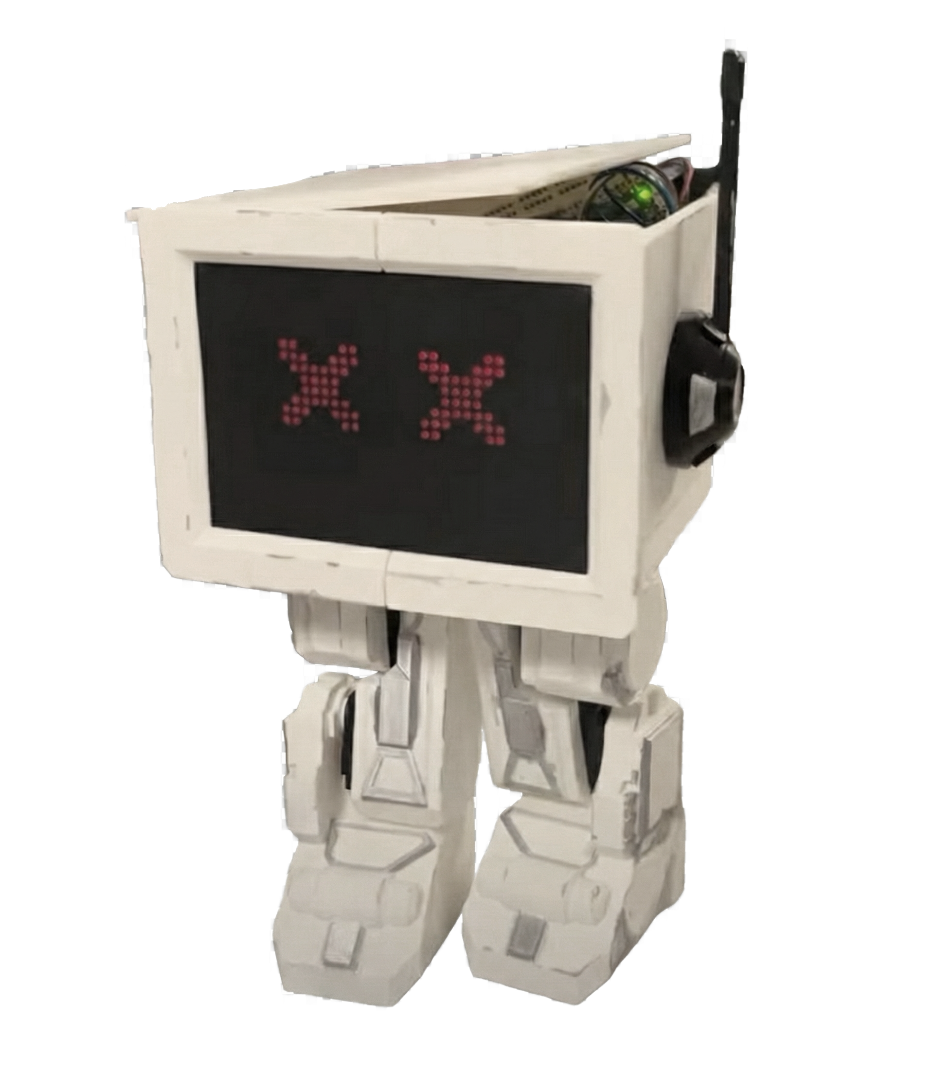
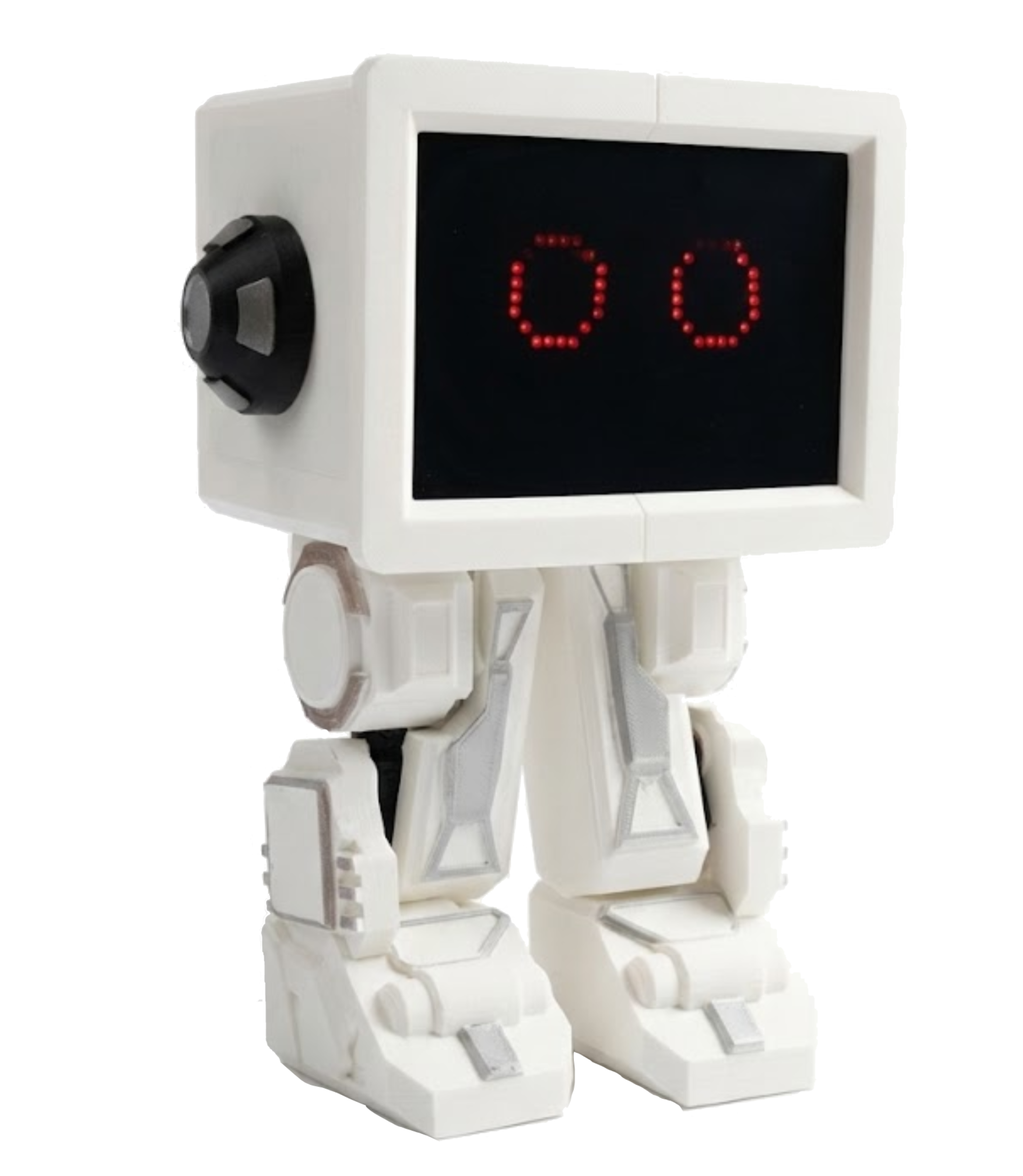
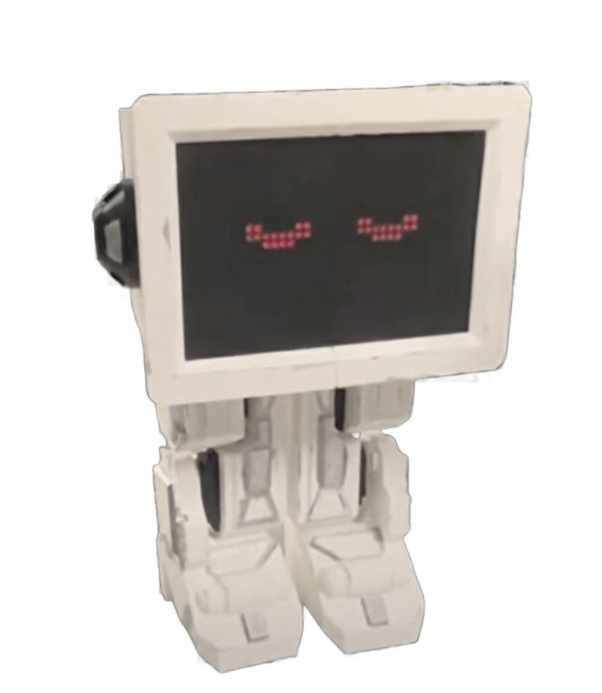
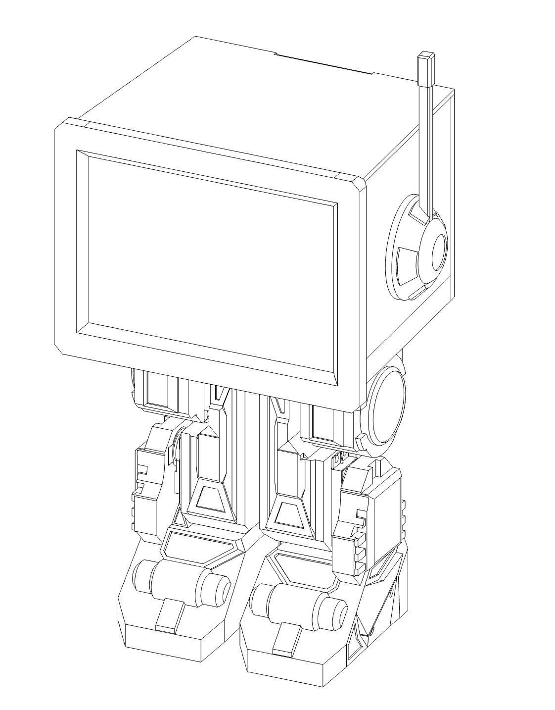
In this project, we designed and built Bebe, a two-legged bipedal robot controlled by a Raspberry Pi Pico W. Each leg uses three servo motors at the hip, knee, and ankle, driven with PWM to coordinate stepping, posture, and balance. Bebe also displays simple emotional expressions through animated eyes, providing clear visual feedback during operation.
Interactive 3D View: Drag to rotate.
Movement commands are generated using a separate handheld wand built around another Pico and an IMU. By tilting the wand, the user can intuitively control Bebe's direction and motion without relying on buttons or complex interfaces. The goal of this project was to explore intuitive human-robot interaction while addressing the challenges of coordinated bipedal movement using a resource-constrained embedded system.
Demo Video
2. High Level Design
Rationale and Sources of Project Idea
Bebe was motivated by a simple question: can we make bipedal motion feel intuitive rather than programmed? Most small robots rely on buttons, joysticks, or pre-scripted sequences. While effective, those interfaces separate the user from the robot's motion. We wanted control to feel physical and immediate, closer to how people naturally communicate movement.
The project draws inspiration from Star Wars, hobby biped robots, motion-controlled toys, and research platforms that use inertial sensing for human input. In particular, gesture-controlled robots and balance-driven walking systems influenced our approach. We focused on coordinated joint motion driven by clear intent from the user. This allowed us to study bipedal kinematics, PWM based servo control, and wireless communication within a realistic embedded systems scope.
Our design choices were informed by concepts from embedded control, kinematics, and sensor fusion introduced in coursework and public resources. The goal was not to replicate a research grade humanoid, but to build a reliable, expressive system that demonstrates coordinated motion, real time control, and clean system organization.
Background Information
PWM
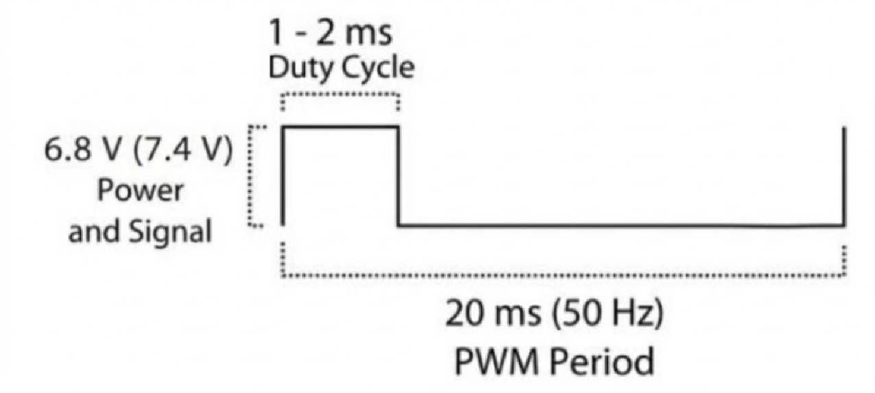
Bebe's motion is driven by standard positional servo motors controlled using PWM. Each servo expects a fixed frequency signal (50 Hz), where the pulse width determines the desired angle. In this system, each servo receives a signal at a fixed frequency of 50 Hz, meaning the signal repeats every 20 ms. The servo does not respond to the overall duty cycle, but instead reads the width of the high pulse within each cycle. Different pulse widths correspond to different target angles, with shorter pulses corresponding to the smaller angles and longer pulses to larger angles. Internally, the servo compares the desired position from the PWM signal to its current position and drives its motor until the two match. Using a fixed, stable PWM signal allows Bebe to achieve consistent joint motion across all servos.
This relationship allows joint angles to be mapped linearly to PWM duty cycles. Each leg contains three joints: hip, knee, and ankle, so coordinated motion is achieved by commanding consistent angle trajectories across these joints.
IMU Orientation Calculations
The control wand uses an inertial measurement unit (IMU) to estimate its orientation in space. The IMU provides two primary sources of data: a three axis accelerometer and a three axis gyroscope. Each sensor measures a different physical quantity, and each has different strengths and weaknesses.
The accelerometer measures linear acceleration along the x, y, and z axes. When the wand is stationary or moving slowly, the dominant acceleration it senses is gravity. This allows the accelerometer to be used as an absolute reference for tilt. The measured values are first converted from raw sensor units into acceleration in units of g. From these values, tilt angles can be computed using basic trigonometry.
For example, pitch and roll can be estimated as:
Roll is computed using the ratio of lateral acceleration to vertical acceleration:
$$ \text{roll} = \text{atan2}(a_y, a_z) $$Pitch is computed using the forward acceleration and the magnitude of the other two axes:
$$ \text{pitch} = \text{atan2}(-a_x, \sqrt{a_y^{2} + a_z^{2}}) $$These equations assume gravity is the primary acceleration acting on the sensor. As a result, accelerometer based angles are stable in the long term but become noisy when the wand is moving or experiencing vibrations. The gyroscope measures angular velocity around each axis, typically in degrees per second or radians per second. These values describe how fast the wand is rotating, not its absolute orientation. To estimate orientation from the gyroscope, the angular velocity is integrated over time:
$$ \text{angle}(t) = \text{angle}(t-1) + \omega \cdot \Delta t $$where $\omega$ is the measured angular rate and $\Delta t$ is the time between samples. Gyroscope based angles respond quickly and smoothly to motion, but small measurement errors accumulate over time, causing drift.
To take advantage of both sensors, the system combines accelerometer and gyroscope estimates using a complementary filter. The idea is to trust the gyroscope for short term motion and trust the accelerometer for long term stability.
For each axis, the filtered angle is computed as:
$$ \text{filtered_angle} = \alpha \cdot (\text{previous_angle} + \text{gyro_rate} \cdot \Delta t) + (1 - \alpha) \cdot \text{accel_angle} $$The constant $\alpha$ is chosen close to 1, typically around 0.95 to 0.99. This weighting ensures that fast, smooth motion comes from the gyroscope, while slow drift is corrected by the accelerometer.
In our system, $\theta$ and $\phi$ are used to convert the wand's continuous orientation into simple, intentional movement commands. $\theta$ represents the horizontal direction of motion, such as forward, backward, left, or right. It is computed from the filtered roll and pitch angles by projecting the wand's tilt onto the horizontal plane and taking the angle of that projection. In practice, this is done using an atan2 operation, which produces a stable directional angle across all quadrants.
$\phi$ represents the magnitude of the tilt, independent of direction, and is computed as the overall tilt angle from vertical. This value is obtained from the magnitude of the pitch and roll components. $\phi$ acts as an activation threshold rather than a direction command. When $\phi$ remains below a chosen limit, the robot stays idle. Once $\phi$ exceeds that threshold, motion is enabled and the robot moves in the direction specified by $\theta$. This separation allows small unintentional movements of the wand to be ignored, while larger, deliberate gestures result in clear and predictable robot motion.
By using this approach, the wand provides intuitive, low latency control without requiring complex sensor fusion algorithms. The math is simple enough to run reliably on a microcontroller while still producing stable and responsive orientation estimates.
Wi-Fi Communication Between Wand and Robot
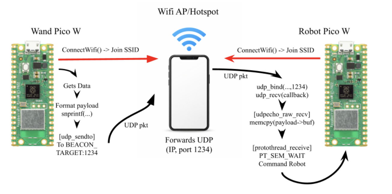
Bebe and the control wand communicate over Wi-Fi using a shared hotspot. Both Pico W boards connect to the same wireless access point, which provides a common local network for data exchange. This setup avoids the need for direct pairing or custom radio protocols and keeps communication simple and reliable.
The control wand acts as the command source. After connecting to the hotspot, it periodically sends motion data packets containing the computed control values derived from the IMU, including direction and activation state. These packets are transmitted using lightweight UDP messages, which minimizes latency and avoids the overhead of connection management.
On the robot side, Bebe listens on a predefined port for incoming packets. When a packet is received, the robot parses the data and updates its internal motion state. This state is then consumed by the motion control logic, which updates servo targets accordingly. Because UDP is non blocking and connectionless, the robot can continue running its control loop even if packets are briefly delayed or dropped. Newer packets simply overwrite older commands, ensuring that Bebe always responds to the most recent user input.
This communication model provides fast, responsive control while keeping the software architecture straightforward. It also cleanly separates sensing and decision making on the wand from actuation on the robot.
Logical Structure
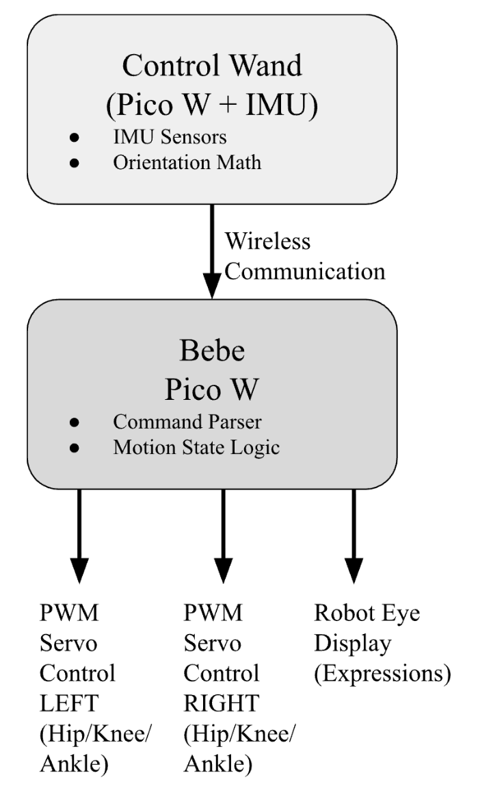
The system is divided into two cooperating devices: the robot body and the control wand.
The control wand continuously reads IMU data, computes orientation, and translates that orientation into motion commands. These commands are transmitted wirelessly to the robot via wifi.
On the robot side, incoming commands update a shared control state. A central control loop interprets this state and updates servo targets accordingly on Core 0. Servo outputs are generated using PWM hardware on the Pico W, ensuring consistent timing without blocking the main loop.
Visual feedback is handled independently through the eye display system on Core 1. Expressions are updated based on a pre-programmed sequence, but can also be programmed to be random or dependent on the robot's current motion or state, such as idle, moving, or turning. This separation allows motion control and expression to run concurrently without interfering with each other.
Hardware/Software Tradeoffs
A major tradeoff was avoiding closed-loop balance control. Without force sensors, Bebe relies on static stability and tuned joint angles. This reduced complexity but limited agility. We also chose servos over DC motors with encoders to simplify position control at the cost of torque efficiency. In software, we prioritized deterministic timing (predefined poses) over real-time inverse kinematics to ensure stability on the microcontroller.
Intellectual Property Considerations
Bebe uses standard hobbyist techniques (PWM servos, IMU sensing) and does not infringe on proprietary walking algorithms. No copyrighted assets were used. All libraries (MAX72XX, Wi-Fi drivers) are open source.
3. Program/Hardware Design
Hardware Design
Mechanical Design
Bebe's mechanical structure was designed using CAD software to ensure proper joint placement, weight distribution, and structural integrity. The robot's frame supports six servo motors positioned at the hip, knee, and ankle joints of each leg, allowing for coordinated bipedal motion. The design prioritizes stability and balance while maintaining a compact form factor suitable for the Pico W controller and power systems. Disney droids were used as inspiration for the design. We also sued Fusion, our CAD software of choice's center of gravity tool to check stability.
All of the robot's components were 3D printed using PLA filament and assembled together using screws and hot glue.
Aesthetics
All of Bebe's components were 3D printed using PLA filament, allowing for precise fabrication of the joint structures and body frame. The 3D printing process enabled rapid iteration during the design phase, making it easy to test different joints and refine the robot's form factor.
The visual design of Bebe draws inspiration from Disney droids, particularly the weathered and characterful appearance seen in Star Wars films, as well as the distinctive art styles found in video games.
The weathering process was designed to make Bebe feel like a functional, used robot rather than a prototype.
Electrical Hardware
Bebe's electrical hardware is organized around two main subsystems: actuation and interaction. The system is built to provide reliable servo control, electrical isolation for safety, and clear visual feedback, all while staying within the limits of the Pico W.
Microcontroller
The robot is controlled by a Raspberry Pi Pico W, which serves as the central controller for motion, communication, and display. The Pico W was chosen for its built-in Wi-Fi, multiple hardware PWM channels, and sufficient GPIO to support servo control and external peripherals.
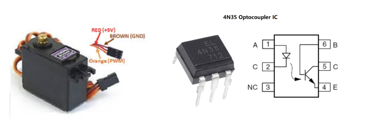
Servo Motors and Actuation - MG996R Servos
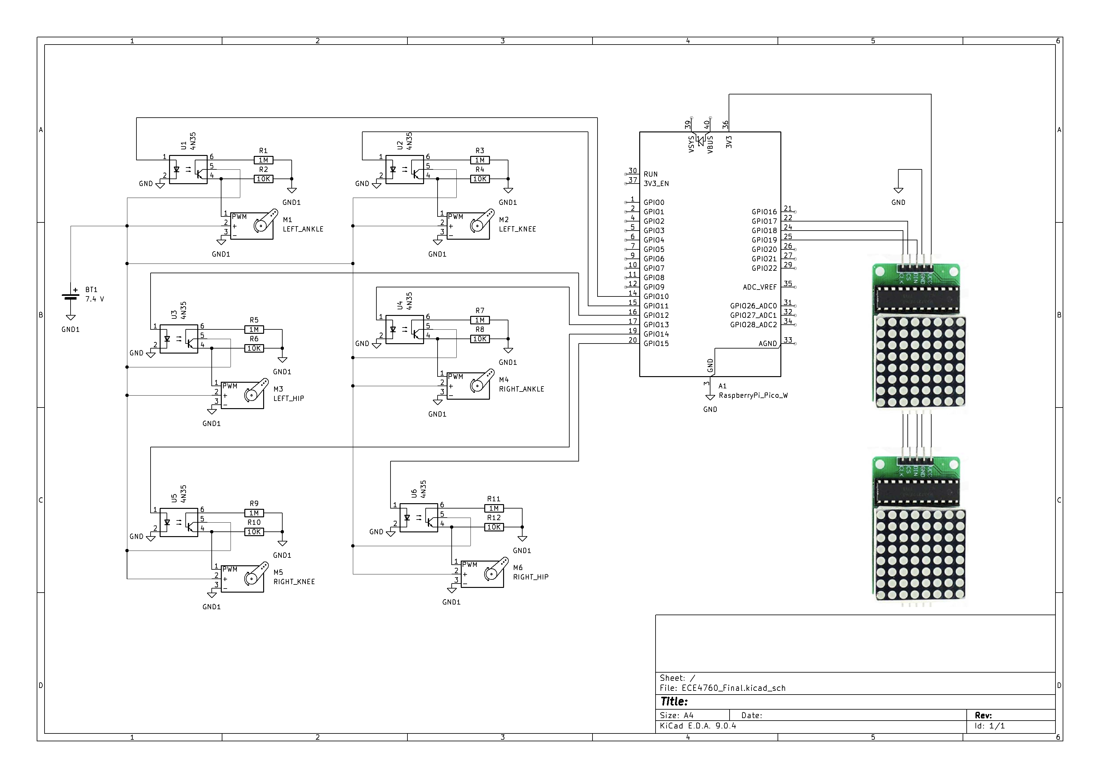
Bebe uses six positional servo motors in total, three on each leg, corresponding to the hip, knee, and ankle joints. These servos are driven using PWM signals generated by the Pico W. Each servo receives a fixed-frequency control signal, with pulse width determining the commanded joint angle.
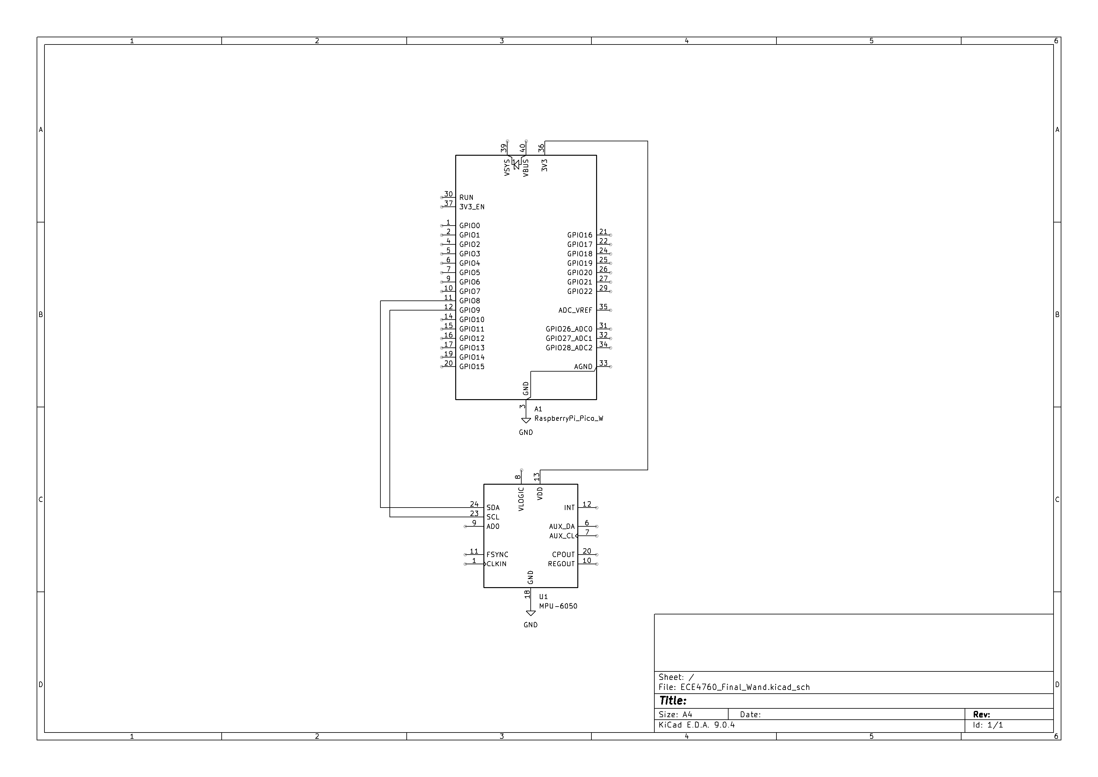
To protect the microcontroller and improve signal reliability, opto-isolators (4N35) are used between the Pico W GPIO pins and the servo control lines. The opto-isolators electrically separate the low-power logic side from the higher-current servo side, preventing voltage spikes and electrical noise generated by the motors from feeding back into the microcontroller. This isolation proved especially important during rapid joint movement, where current draw and noise are highest.
The servos are powered from an external supply capable of delivering sufficient current for simultaneous motion. Grounds are carefully managed so that the logic and power domains remain stable while still allowing correct signal referencing through the opto-isolators.
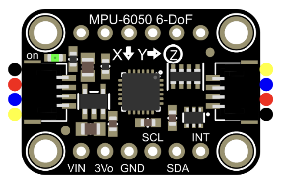
IMU Sensor - MPU6050
The control wand includes an inertial measurement unit used to capture user motion. The IMU contains a three-axis accelerometer and three-axis gyroscope, allowing measurement of linear acceleration and angular velocity. These signals are read by a separate Pico and processed to estimate orientation and motion intent. The resulting control values are transmitted wirelessly to the robot, keeping sensing and actuation physically and electrically decoupled.
Robot Eyes Display
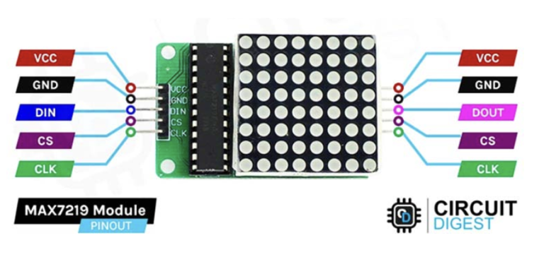
Bebe displays emotional expressions using two MAX7219-based LED dot matrix display modules. For driving the LED matrix, we used the MD_MAX72XX library by MajicDesigns (available on GitHub). Each module drives an 8x8 LED matrix, allowing the robot to render simple eye shapes and animations. The displays are controlled using a serial interface, which minimizes the number of required GPIO pins.
The MAX7219 handles LED multiplexing and current regulation internally, reducing software complexity and ensuring consistent brightness across the display. Using two separate matrices allows independent control of each eye, making expressions more readable and expressive during motion.
Power Considerations
Power for the servo motors and logic circuitry is supplied separately to prevent brownouts and unintended resets. The Pico W and display modules operate at logic-level voltages, while the servos draw higher current from the external supply. This separation, combined with optical isolation, improves system stability and protects sensitive components during dynamic movement.
Software Design
Bebe's software is split across two Raspberry Pi Pico W boards that work together: the robot controller and the control wand. Each board runs a focused, single responsibility program. The wand handles sensing and intent. The robot handles motion, expression, and actuation. This separation keeps timing predictable and makes debugging far easier.
At a high level, the wand reads IMU data, converts orientation into motion commands, and transmits them over Wi-Fi. The robot listens for those commands, updates a shared motion state, and drives servos and eye animations accordingly.
Robot Controller Software
The robot-side software runs on the Pico W mounted on Bebe's body. Its main responsibilities are:
- Receiving motion commands over Wi-Fi
- Generating PWM signals for six servos
- Updating eye expressions independently of motion
Motion State and Control Loop
Incoming commands update a shared motion state that represents the robot's current intent, such as forward motion, turning, or idle. The control loop continuously reads this state and selects predefined joint angle targets for the hip, knee, and ankle servos on each leg.
Rather than computing inverse kinematics in real time, the system uses predefined poses and transitions. This makes motion deterministic and avoids instability from noisy inputs. Each walking step is implemented as a sequence of stable poses that shift the robot's center of mass gradually.
The control loop structure is simple:
- Read latest motion command
- Select target pose or transition
- Increment servos toward target angles
- Repeat at a fixed update rate
This approach prioritizes stability over speed, which is critical for a small biped without balance sensors.
PWM Servo Control
PWM signals for Bebe's servos are generated using the RP2040's hardware PWM peripheral to ensure precise timing. The system clock is divided to produce a 1 MHz PWM clock, giving 1 µs resolution for pulse width control. The PWM wrap value is set to 20,000, resulting in a 20 ms period (50 Hz) that matches the servo requirements. With this configuration, the PWM channel level directly corresponds to the pulse width in microseconds, allowing servo positions to be specified easily. Pulse widths are constrained to a safe operating range based on the servo datasheet to prevent mechanical overextension, and updates to the PWM output are synchronized with the PWM interrupt and only applied when the desired value changes.
Although PWM timing is generated by the microcontroller, the servos are powered using an external 7 V battery, as the RP2040's 3.3 V supply was insufficient to drive the servos reliably. This configuration improved signal reliability and prevented erratic behavior during operation.
Each servo was calibrated to determine its true midpoint and usable range. Each joint was tested by sweeping pulse widths and observing the resulting angles to identify the pulse width corresponding to a true 90-degree bend. These calibrated midpoint values were then used as reference positions for all joint motions.
We also initially had some jitter in the servo control, but we were able to fix it by implementing smooth servo control. Eg. moving the servo through discrete steps rather than directly to the desired angle.
Coordinated leg motion is achieved by commanding relative offsets from these midpoint values. Forward motion begins by lifting a thigh through an increase in the hip joint pulse width while simultaneously rotating the ankle downward to clear the ground. To maintain stability during this phase, the opposing leg bends at the knee and ankle to support the robot's weight. While the lifted leg remains elevated, the previously bent leg is then moved forward. The lifted leg is subsequently returned to its midpoint position and placed back on the ground, after which both legs are returned to balanced positions. By sequencing these joint motions across both legs, Bebe achieves stable and repeatable walking behavior using simple open-loop PWM-based position control.
Eye Expressions and Animation
Bebe's visual expressions are rendered using two MAX7219 driven LED matrix modules, one for each eye. Each module controls an 8×8 LED grid and handles all low level LED multiplexing and current regulation internally. This offloads timing critical display work from the Pico W and allows the main processor to focus on motion control and communication.
The robot uses the MD_MAX72XX library to communicate with the MAX7219 over a simple serial interface. This library abstracts the register level details of the driver chip and provides direct control over individual LEDs and display buffers. As a result, updating an eye frame is reduced to writing a small set of bytes rather than manually managing row and column scanning.
Eye behavior is implemented as a lightweight animation system built on top of this library. Each animation consists of a sequence of frames, where each frame encodes both the visual state of the eyes and how long that state should be displayed. A single frame is represented by the following structure:
typedef struct {
    uint8_t eyeData[2];
    uint16_t timeFrame;
    bool flip;
} animFrame_t;
The eyeData field stores bitmap information for the left and right eye, allowing asymmetric expressions such as winks or glances. The timeFrame field specifies how long the frame should remain visible in milliseconds, which makes animation timing explicit and easy to adjust. The optional flip flag allows the same bitmap data to be reused for mirrored expressions without duplicating assets in memory.
Animation sequences are stored as arrays of these frame structures. A simple sequence might alternate between two frames to simulate blinking, while more expressive sequences combine multiple frames with different durations to create emotions such as curiosity, surprise, or alertness. The animation engine advances through frames using a non blocking timing check, ensuring that display updates never stall the main control loop.
In the current implementation, the robot cycles through predefined animation sequences regardless of motion. This choice keeps the system predictable and avoids unintended coupling between motion and expression during debugging. However, the animation system is designed to be state driven. Because each frame sequence is selected through a simple index or pointer, it can easily be mapped to higher level robot states. For example, an idle state could trigger slow blinking, walking could use focused forward looking eyes, and turning could bias one eye to suggest direction.
Display updates are intentionally lightweight. Updating the LED matrices involves sending a small number of bytes over the serial interface, and the MAX7219 handles refresh internally. As a result, eye animations run concurrently with servo motion without affecting PWM timing or network responsiveness. Even during continuous walking, expression updates remain smooth and consistent.
This separation of expression from motion reinforces the robot's behavior at a human perceptual level. Motion communicates intent through physical action, while the eyes provide continuous visual feedback that makes the robot feel more expressive and alive. Just as importantly, the software architecture keeps these two systems independent, making the overall system easier to extend and reason about.
Control Wand Software
The control wand runs on a separate Raspberry Pi Pico W and serves as the sole source of user intent. Its role is to interpret natural hand motion and convert it into simple, reliable motion commands.
IMU Sampling and Orientation Estimation
The wand continuously samples an MPU6050 inertial measurement unit at a fixed update rate. The IMU provides raw accelerometer and gyroscope readings along three axes. These raw values are first converted into physical units using scale factors defined by the sensor configuration. Accelerometer readings are converted to units of g, and gyroscope readings are converted to angular velocity in degrees per second or radians per second.
Neither sensor alone is sufficient for stable orientation estimation. Accelerometer based angles are absolute and drift free, but they are noisy and unreliable during motion. Gyroscope based angles respond smoothly and accurately to rotation, but small measurement errors accumulate over time and lead to drift. To combine the strengths of both, the wand uses a complementary filter.
At each update step, the filtered orientation angle is computed as:
$$ \text{angle} = \alpha \cdot (\text{previous_angle} + \text{gyro_rate} \cdot \Delta t) + (1 - \alpha) \cdot \text{accel_angle} $$The gyroscope term predicts how the angle has changed since the last sample, while the accelerometer term slowly corrects long term drift. The weighting constant $\alpha$ is chosen close to 1, so short term motion is dominated by the gyroscope while long term stability comes from the accelerometer. This filter is simple enough to run reliably on a microcontroller while still producing smooth, stable orientation estimates.
Filtered roll and pitch angles are maintained continuously and updated at a constant rate. These angles form the foundation for all user input to the robot.
Command Extraction and Intent Mapping
Rather than sending raw angles to the robot, the wand converts orientation into two higher level control parameters: $\theta$ and $\phi$. This abstraction simplifies communication and makes robot behavior easier to tune.
$\theta$ represents the intended direction of motion in the horizontal plane. It is computed by projecting the filtered roll and pitch angles onto that plane and using an atan2 operation to calculate the resulting angle. Using atan2 ensures that the direction remains continuous and unambiguous across all quadrants, avoiding discontinuities that would otherwise occur at angle boundaries.
$\phi$ represents the magnitude of the tilt, independent of direction. It is computed from the combined magnitude of the roll and pitch angles and serves as an activation signal rather than a directional command. Small values of $\phi$ indicate that the wand is nearly upright, while larger values indicate deliberate user input.
This separation of direction and activation is critical for usability. When $\phi$ remains below a predefined threshold, the wand sends an idle or stop command. This prevents unintended robot movement caused by small hand tremors or noise in the sensor readings. Once $\phi$ exceeds the threshold, motion is enabled and $\theta$ determines whether the robot moves forward, backward, or turns.
By reducing continuous orientation data into discrete, intentional commands, the wand provides intuitive control while shielding the robot from sensor noise and ambiguous inputs.
Wi-Fi Communication and Command Transmission
After connecting to a shared Wi-Fi hotspot, the wand periodically transmits motion commands to the robot using UDP packets. Each packet contains the current command values derived from $\theta$ and $\phi$, along with any required state flags. Packets are sent at a fixed rate, ensuring low latency and predictable updates.
UDP was chosen over connection oriented protocols because it introduces minimal overhead and does not block the system waiting for acknowledgments. The wand simply transmits the most recent command, regardless of whether the previous packet was received.
On the robot side, a UDP listener waits on a predefined port for incoming packets. When a packet arrives, its contents are parsed immediately and used to update the robot's shared motion state. Because new packets overwrite older values, the robot always responds to the latest user input. Temporary packet loss does not degrade behavior, as the next packet arrives shortly after.
This communication model is fast, non blocking, and resilient. It allows the wand to operate independently of the robot's control loop while still maintaining responsive, real time control. Most importantly, it keeps the overall system simple. Sensing, interpretation, and actuation are cleanly separated, which makes the behavior easier to understand, debug, and extend.
Concurrency and Timing
The system relies on separation rather than preemption to manage concurrency. On the robot:
- Hardware PWM handles servo timing
- Eye animations run independently of motion logic
- Networking does not block the control loop
On the wand:
- IMU sampling runs at a fixed interval
- Orientation estimation and packet transmission are lightweight
This structure avoids complex scheduling while still allowing sensing, communication, motion, and expression to operate concurrently and reliably.
4. Results of the Design
Overall Performance
Overall, Bebe performed reliably and consistently during testing, demonstrating responsive behavior with low perceived latency between wand input and motion execution. Walking motions were executed smoothly without noticeable hesitation, jitter, or unexpected stalls, and the robot maintained a stable posture during controlled testing. Control logic, servo actuation, and visual output operated concurrently, allowing servo motion, eye animation, and communication to run in parallel without visible timing conflicts. PWM timing remained stable at 50 Hz, producing repeatable joint trajectories across all legs, indicating accurate pulse-width generation and effective servo calibration. Safety was enforced through software limits that constrained PWM pulse widths and through motion sequencing that avoided abrupt joint movements. During the demonstration using a battery pack to power the microcontroller, the additional and unaccounted-for weight altered the robot's weight distribution, making it more prone to tipping. While the robot was not able to walk consistently under these conditions, it was still able to produce the intended joint motions, highlighting that the logic and servo control functioned as designed. This behavior revealed a limitation related to mass distribution and stability that could be addressed in future iterations.
Test Data, Scope Traces, and Waveforms
Oscilloscope measurements were used extensively during development to verify correct signal generation, particularly for PWM based servo control. Each servo control line was probed to confirm both frequency and pulse width.
The PWM signals driving the servos operated at 50 Hz, as required by standard positional servos. Scope traces confirmed a stable 20 ms period with pulse widths varying between approximately 1.0 ms and 2.0 ms, corresponding to joint angles from 0 to 180 degrees. These measurements matched the expected mapping used in software and confirmed that the Pico W's hardware PWM was configured correctly.
Wi-Fi communication was tested by monitoring packet reception rates and observing robot response. Commands sent from the wand resulted in visible servo motion within a fraction of a second. Even when packets were intentionally dropped or delayed, the robot continued operating using the most recent valid command, demonstrating tolerance to transient communication issues.
In software, motion commands were bounded to prevent servos from exceeding safe mechanical limits. Joint angles were clamped to ranges that had been physically tested and verified not to cause binding or excessive torque.
The control wand design also contributed to safety. By requiring a minimum tilt magnitude before motion was enabled, the robot remained idle unless the user made a deliberate gesture. Loss of communication naturally resulted in the robot holding its last safe pose rather than entering an uncontrolled state.
Safety Enforcement
- Software Limits: Joint angles were clamped in software to prevent mechanical binding.
- Dead Man's Switch: The wand requires a minimum tilt ($\phi$) to activate. If the user drops the wand or holds it level, the robot stops immediately.
- Electrical Isolation: Optocouplers protected the logic hardware from power surges.
Usability and Human Interaction
From a user perspective, Bebe was easy to control and intuitive to operate. Using the wand felt more natural than buttons or joysticks, especially for directional control. Users were able to understand how to move the robot within seconds, without instruction beyond a brief demonstration.
Other users who interacted with the system reported that the robot's behavior was predictable and responsive. The combination of physical motion and expressive eyes made it clear when the robot was active, idle, or responding to input. This visual feedback helped users build confidence in the robot's behavior.
The separation between direction and activation made the interface forgiving. Users could reposition their hands or relax their grip without accidentally triggering motion. Overall, the system felt interactive rather than mechanical, which aligned well with the original project goals.
5. Conclusions
Overall, the results of the design largely met our expectations. Bebe was able to execute the intended joint motions reliably and demonstrated stable behavior during controlled testing. The open-loop PWM-based control strategy proved sufficient for producing coordinated walking motions, validating the servo calibration and joint motion timing. However, testing with additional onboard mass revealed sensitivity to weight distribution, which increased the likelihood of tipping during walking. In future iterations, this limitation could be addressed through improved mass placement, structural redesign, or by adding additional degrees of freedom at the feet to allow more active balance control during stance and transition phases.
The design conforms to applicable electrical and signaling standards for servo control, including the use of a 50 Hz PWM control signal and pulse-width limits specified by the servo datasheet. Electrical safety was maintained by respecting voltage and current requirements and by enforcing software limits to prevent mechanical overextension. All components were operated within their recommended operating conditions.
From an intellectual property perspective, the project did not involve reverse engineering of proprietary designs or the use of confidential information. The base implementation relied primarily on instructor-provided demonstration code for the coursework and reference materials used for the robot eye animations, the MD_MAX72XX library by MajicDesigns (available on GitHub). All other aspects of the design and control logic were developed independently without consulting or reusing other teams’ designs. No public-domain code was used, no non-disclosure agreements were required, and no patent or trademark conflicts were identified. The current implementation does not present any apparent patent opportunities.
Appendices
Appendix A: Permissions
The group approves this report for inclusion on the course website.
The group approves the video for inclusion on the course youtube channel.
Appendix B: Code
Appendix C: Schematics
Please refer to the Hardware section above for circuit details regarding the Servo connections (4N35 Optocouplers) and MAX7219 pinouts.
Appendix D: Work Distribution
- Peter: Mechanical design (CAD), Electrical design, Integration hell, Walk code.
- Ronald: Wand IMU logic, WIFI logic, Emotions.
- Wang: Walk cycle, Balance code, Servo PWM code.
AI Statement
We used ChatGPT for some help with website styling, but most of the website code was written ourselves.