Project Introduction

A wireless audio transceiver system using Raspberry Pi Pico W and UDP.

By Owen Neuman and Pengcheng Zhang

Read Report

High Level Design

Rationale and Sources of Inspiration

We wanted to create a project that incorporated topics covered in labs as well as new elements. Utilizing the Pico W as an audio transmitter/receiver, essentially transforming units into walkie-talkies, accomplished this goal. Additionally, the devices are able stream music when in receive mode using a PC to broadcast the audio data. 
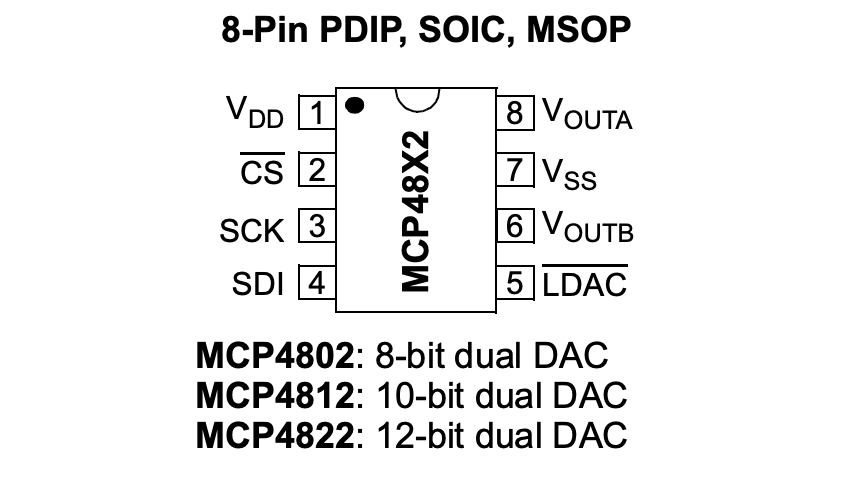
The use of a DAC for audio sampling was a core component of the birdsong and Galton Board Labs, and played a fundamental role in our final project. The use of the RP 2040 ADC input pins, introduced in the Galton Board lab, was a significant aspect of our project as well. However, the realm of Wi-Fi connection and UDP communication was a topic not covered during the labs, which we thought would be fun to explore. The dual broadcast/receive functionality adds extra complexity, with both devices able to toggle between modes. The concept of state change was a fundamental aspect of labs 1 and 2, which served as a source of inspiration for this feature. Dr. Adams' lecture on UDP communication and the accompanying demo code on the course website were a helpful starting point.

Logical Structure & Tradeoffs

The primary software/hardware tradeoffs involve managing network overhead while maintaining the high sampling rate of 44.1KHz. Although this rate exceeds the sampling rate needed to capture the full human vocal range, it is optimal when streaming music and adds an extra constraint to the project for the sake of a challenge. The architecture carefully separates timing-critical real-time operations (handled by the ISR) from bursty network I/O (managed by cooperative protothreads), using double-buffering on the transmit path and a thread-safe circular queue on the receive path to decouple these domains. Audio packets of 1024 samples (11.6 ms, 2048 bytes) are transmitted approximately 86 times per second, balancing network efficiency against latency. The receive buffer holds 8192 samples (~185 ms), providing substantial tolerance for WiFi jitter at the cost of end-to-end latency. A low-pass filter with 5-6 kHz cutoff is applied to microphone input to reduce noise while preserving voice intelligibility. The system runs entirely on a single core with lock-free synchronization primitives, prioritizing audio timing integrity over network responsiveness—a necessary tradeoff given the RP2040's resource constraints. While uncompressed PCM transmission is bandwidth-intensive, it minimizes CPU overhead and latency, making it suitable for real-time voice communication where the ~200 ms total system latency (buffering + network + processing) remains acceptable for conversational use.

Background Mathematics & System Architecture

Sample rate: 44,100 Hz | Stereo: 2 samples captured per ISR call (duplicated mono) | Buffer size: 1024 samples (512 stereo pairs)
Time to fill buffer: 1024 samples / (2 samples/ISR * 44,100 Hz) ≈ 11.6 ms
Packets per second: 1000 ms / 11.6 ms ≈ 86 packets/second
┌─────────────────────────────────────────────────────────────────────────────┐
│                     RASPBERRY PI PICO W AUDIO STREAMING SYSTEM              │
│                              (Single Core - Core 0)                         │
└─────────────────────────────────────────────────────────────────────────────┘

                              HARDWARE LAYER
┌──────────────────┐  ┌──────────────────┐  ┌──────────────────┐
│   Microphone     │  │   MCP4822 DAC    │  │   WiFi Module    │
│   (GPIO 26)      │  │   (SPI0)         │  │   (CYW43439)     │
│   ADC0 12-bit    │  │   Dual 12-bit    │  │                  │
└────────┬─────────┘  └────────┬─────────┘  └────────┬─────────┘
         │                     │                     │
         │ Analog              │ SPI @ 20MHz         │ SDIO
         │                     │ (blocking)          │
         ▼                     ▼                     ▼
┌─────────────────────────────────────────────────────────────────────────────┐
│                           INTERRUPT SERVICE ROUTINE                         │
│                        (TIMER_IRQ_0 - Priority 0x00)                        │
│                          Fires every 22.68 μs (44.1 kHz)                    │
├─────────────────────────────────────────────────────────────────────────────┤
│                                                                             │
│  ┌──────────────────────────────┐    ┌──────────────────────────────┐       │
│  │      TRANSMIT MODE           │    │      RECEIVE MODE            │       │
│  │                              │    │                              │       │
│  │  1. adc_read()               │    │  1. deQueue() L sample       │       │
│  │  2. Low-pass filter          │    │  2. deQueue() R sample       │       │
│  │     (exponential average)    │    │  3. Format for DAC           │       │
│  │  3. Store to tx_write_buffer │    │  4. spi_write16_blocking()   │       │
│  │  4. When full (1024 samples) │    │  5. Pulse LDAC pin           │       │
│  │     → Swap buffers           │    │                              │       │
│  │     → Set tx_buffer_ready    │    │  If buffer empty:            │       │
│  │                              │    │     → Stop playback          │       │
│  └──────────────────────────────┘    └──────────────────────────────┘       │
│                                                                             │
└─────────────────────────────────────────────────────────────────────────────┘
                    ▲                                    ▲
                    │ Highest Priority                   │ Preempts
                    │ (preempts all)                     │
                    │                                    │
┌───────────────────┴────────────────────────────────────┴───────────────────┐
│                         BUFFERING & SYNCHRONIZATION                        │
├────────────────────────────────────────────────────────────────────────────┤
│                                                                            │
│  TRANSMIT PATH (Double Buffer):                                            │
│  ┌──────────────────┐          ┌──────────────────┐                        │
│  │ tx_write_buffer  │  swap    │ tx_send_buffer   │                        │
│  │ (ISR writes)     │ ◄─────►  │ (thread reads)   │                        │
│  │ 1024 samples     │          │ 1024 samples     │                        │
│  └──────────────────┘          └──────────────────┘                        │
│           │                              │                                 │
│           │ tx_buffer_ready flag         │                                 │
│           ▼                              ▼                                 │
│                                                                            │
│  RECEIVE PATH (Circular Queue):                                            │
│  ┌───────────────────────────────────────────────────────────┐             │
│  │        CircularQueue<uint16_t, 8192>                      │             │
│  │        Thread-safe (atomic start/end indices)             │             │
│  │        ~185ms buffer at 44.1kHz stereo                    │             │
│  │                                                           │             │
│  │   [UDP writes] ──enQueue()──► │ │ │ ──deQueue()──► [ISR]  │             │
│  │                               ▲                           │             │
│  │                  512 samples = playback start threshold   │             │
│  └───────────────────────────────────────────────────────────┘             │
│                                                                            │
└────────────────────────────────────────────────────────────────────────────┘
                    ▲                                    │
                    │ enQueue()                          │ Packet ready
                    │                                    ▼
┌─────────────────────────────────────────────────────────────────────────────┐
│                    COOPERATIVE PROTOTHREAD SCHEDULER                        │
│                         (Lower Priority - Yields CPU)                       │
├─────────────────────────────────────────────────────────────────────────────┤
│                                                                             │
│  ┌──────────────────────┐  ┌──────────────────────┐  ┌─────────────────┐    │
│  │ protothread_tx_audio │  │ protothread_receive  │  │ protothread_send│    │
│  │                      │  │                      │  │                 │    │
│  │ Polls every 1ms:     │  │ On semaphore signal: │  │ Serial console  │    │
│  │ if tx_buffer_ready:  │  │ • Calculate bandwidth│  │ UDP test msgs   │    │
│  │   • Allocate pbuf    │  │ • Print stats every  │  │ (user input)    │    │
│  │   • memcpy() data    │  │   1 second           │  │                 │    │
│  │   • udp_sendto()     │  │                      │  │                 │    │
│  │   • pbuf_free()      │  │ Yield every 22μs     │  │                 │    │
│  │ Yield 1ms            │  │                      │  │                 │    │
│  └──────────┬───────────┘  └──────────┬───────────┘  └────────┬────────┘    │
│             │                         │                       │             │
└─────────────┼─────────────────────────┼───────────────────────┼─────────────┘
              │                         ▲                       │
              │ UDP TX                  │ Stats                 │ UDP TX
              ▼                         │                       ▼
┌─────────────────────────────────────────────────────────────────────────────┐
│                         LWIP NETWORK STACK                                  │
│                         (Lower Priority Interrupts)                         │
├─────────────────────────────────────────────────────────────────────────────┤
│                                                                             │
│  ┌────────────────────┐              ┌────────────────────┐                 │
│  │  UDP Transmit PCB  │              │  UDP Receive PCB   │                 │
│  │  Port: 1234        │              │  Port: 1234 (bind) │                 │
│  │  Target: 172.20... │              │                    │                 │
│  └──────────┬─────────┘              └──────────┬─────────┘                 │
│             │                                   │                           │
│             │ Send packets                      │ udpecho_raw_recv()        │
│             │ (~86/sec)                         │ callback on RX            │
│             │                                   │                           │
│             ▼                                   ▼                           │
│  ┌────────────────────────────────────────────────────────┐                 │
│  │              IP Layer (IPv4)                           │                 │
│  │              Adds 20-byte header                       │                 │
│  └────────────────────┬───────────────────────┬───────────┘                 │
│                       │                       │                             │
│                       ▼                       ▼                             │
│  ┌──────────────────────────────────────────────────────────────┐           │
│  │              WiFi Driver (CYW43439)                          │           │
│  │              Handles MAC/PHY layer                           │           │
│  └──────────────────────┬───────────────────────┬───────────────┘           │
└─────────────────────────┼───────────────────────┼───────────────────────────┘
                          │ TX                    │ RX
                          ▼                       ▼
                    ┌────────────────────────────────┐
                    │      WiFi Network (802.11)     │
                    │      ~1.41 Mbps bandwidth      │
                    │      172 KB/s audio data       │
                    │      86 packets/second         │
                    │      2048 bytes/packet         │
                    └────────────────────────────────┘

┌─────────────────────────────────────────────────────────────────────────────┐
│                              TIMING DIAGRAM                                 │
├─────────────────────────────────────────────────────────────────────────────┤
│                                                                             │
│  ISR fires:     |---22.68μs---|---22.68μs---|---22.68μs---|---22.68μs---    │
│                 ▲             ▲             ▲             ▲                 │
│                 │             │             │             │                 │
│  TX: ADC read   ●             ●             ●             ●                 │
│  RX: DAC write  ●             ●             ●             ●                 │
│                                                                             │
│  Buffer swap:   ├─────────── 11.6 ms (1024 samples) ──────────┤             │
│                 │                                                           │
│                 │   tx_buffer_ready                                         │
│                 ▼                                                           │
│  Thread polls:  ◆────1ms────◆────1ms────◆────1ms────◆────1ms────◆           │
│                              │                                              │
│                              │   Detect ready, send packet                  │
│                              ▼                                              │
│  Network RX:    [Packet arrives] ──► Callback ──► enQueue ──► Semaphore     │
│                 (variable timing, ~86/sec average)                          │
│                                                                             │
└─────────────────────────────────────────────────────────────────────────────┘

┌─────────────────────────────────────────────────────────────────────────────┐
│                            DATA FLOW SUMMARY                                │
├─────────────────────────────────────────────────────────────────────────────┤
│                                                                             │
│  TRANSMIT: Mic → ADC → Filter → TX Buffer → UDP → WiFi                      │
│            └─ 44.1kHz ISR ─┘ └─ Double buffer ─┘ └─ Thread ─┘               │
│                                                                             │
│  RECEIVE:  WiFi → UDP → Circular Queue → DAC → Speaker                      │
│            └─ Callback ─┘ └─ Thread-safe ─┘ └─ 44.1kHz ISR ─┘               │
│                                                                             │
│  Bandwidth: 1.41 Mbps (raw audio) + 19 kbps (UDP/IP overhead) = 1.43 Mbps   │
│  Latency:   ~11ms (TX buffer) + ~100ms (network) + ~100ms (RX buffer)       │
│             = ~211ms total end-to-end                                       │
│                                                                             │
└─────────────────────────────────────────────────────────────────────────────┘

Program Details and Logic

Audio Transmission Thread Logic

The audio transmission is handled by a dedicated protothread. It operates in an infinite loop, checking if the device is in transmit mode and if the audio buffer is ready. When ready, the thread allocates a packet buffer (pbuf) from the transport layer. It then copies the 16-bit audio data from the transmit buffer into the packet payload. The packet is sent to the target IP address and port via UDP. After transmission, the pbuf is freed to prevent memory leaks, and the ready flag is cleared to allow the next buffer swap in the ISR.

UDP Reception and Buffering Logic

For receiving audio, the system uses the LWIP raw receive callback. When a UDP packet arrives, the callback verifies the content and copies the payload into a data buffer. The raw bytes are cast to 16-bit samples and enqueued into a circular audio buffer. To ensure smooth playback and mitigate network jitter, the system only begins playing once the circular queue is half-filled (at least 512 samples). Once buffered, a semaphore signals the thread to begin processing.

DAC Output and SPI Synchronicity

The actual audio output is driven by an alarm interrupt occurring 44,100 times per second. In each cycle, the ISR dequeues two 16-bit samples for stereo playback. If the buffer is empty, the system stops playing. For valid samples, the high 4 bits are appended with DAC configuration data (selecting Channel A or B). These values are sent to the DAC via blocking SPI transfers. Finally, the LDAC pin is pulsed low to latch the data from the input registers to the analog output for synchronous playback across both channels.

Hardware Design and Connections

Materials List

  • Raspberry Pi Pico W: Core microcontroller with Wi-Fi capability.
  • MCP-4822 DAC: 12-bit dual-channel digital-to-analog converter.
  • MAX 4466 Microphone: Electret microphone amplifier for audio capture.
  • AmazonBasics computer speakers v216US: Used for audio output.
  • Pi Pico Serial Debug Probe: Used for monitoring and debugging.
  • Miscellaneous: Audio jack, Tactile button, LED, 330 Ohm resistor, Breadboard, and jumper wires.
MCP4822 8-Pin Package Diagram

Note: Package types include 8-Pin PDIP, SOIC, and MSOP.

MAX4466 Microphone Pinout

MAX4466 Electret Microphone Amplifier Pinout

Physical Pin Mapping (Pi Pico W)

Pico W Pin Connection Description
Pins 1, 2, 3 Connected to the serial debugger probe.
Pin 5 330 Ohm resistor connected to a button leading to Ground.
Pin 7 Connected to DAC Pin 2 (Chip Select - CS).
Pin 9 Connected to DAC Pin 3 (Serial Clock - SCK).
Pin 10 Connected to DAC Pin 4 (Serial Data Input - SDI).
Pin 11 Connected to DAC Pin 5 (Latch Data - LDAC).
Pin 12 Connected to an LED leading to Ground.
Pin 31 Connected to the MAX 4466 microphone output.
Pin 36 / 38 Vcc and Ground rails for the breadboard.

Connect DAC pins 6 & 8 (audio output channels) to the audio jack.

Remember to ground the audio jack, DAC, and microphone as well.

You'll need two of everything if you want to make two devices!

Results and Performance Analysis

Bandwidth Metrics

We observed the bandwidth based on the rate of received packets. Streaming from a PC to the Pico proved near ideal, while the Pico W as a transmitter showed significant packet loss. The loss of approximately 50% of audio samples had a significant impact on playback quality.

  • PC Transmitter: Averaged between 170.80 KB/s and 194.61 KB/s.
  • Pico W Transmitter: Averaged between 82.50 KB/s and 87.17 KB/s.

The audio quality was well-preserved when streaming music from a PC(tested with Viva la Vida by Coldplay) from a PC. However, when using the voice transmission feature between Pico units, the audio was distorted. We tested playback with pure sine wave tones and direct ADC-to-DAC connections (no UDP transmission) which eliminated the microphone as a possible source of noise.

Bandwidth Calculations

Theory: 44,100 Hz * 2 channels * 2 bytes/sample = 176,400 bytes/second.
Kilobytes/second: 176,400 / 1024 = 172.27 KB/s.
Network Overhead: 8 bytes (UDP) + 20 bytes (IP) = 28 bytes per packet.
Total Overhead: 86.13 packets/s * 28 bytes ≈ 2.4 KB/s.
Total Ideal Bandwidth: 172.27 + 2.4 = 174.67 KB/s (1,423 kbps).

The bandwidth metrics indicate that packet loss during UDP transmission is the primary cause of the audio distortion. They also suggest that the Pico W's Wi-Fi transmission capabilities may be limited in comparison to that of a PC, which was able to maintain a near ideal bandwidth. It is worth noting that the WiFi network was provided using an iPhone hotspot, which may have contributed to the instability of the connection.

Regulations, Safety, and IP

Safety Precautions

Soldering was required to connect header pins to the Pico W and microphones. Eye protection was worn at all times during soldering. We also ensured the supply voltage to the breadboard was disconnected when adjusting any wiring.

Standards & Regulations

As this project uses Wi-Fi to transmit signals, it qualifies as an intentional radiator under FCC Part 15 regulations. We ensured compliance by using the stock Pico W module, which carries FCC certification, and avoided modifying the antenna or firmware.

Intellectual Property

The UDP demo code is the intellectual property of Andrew McDonnell (Copyright 2022). The LWIP stack was originally developed by Adam Dunkels and is open source. No patent opportunities were pursued, and no non-disclosure agreements were required.

Conclusions and Future Work

The design met expectations for PC-to-Pico streaming but showed packet loss limitations in Pico-to-Pico transmission. If given more time, we would explore strategic physical orientation of the network access point, Wi-Fi Pico W antenna, and surrounding jumper wires in the hopes of mitigating packet loss. Another interesting area for exploration is the implementation of a software audio mixer using potentiometers for volume, bass, mid, and treble control, potentially utilizing an FFT for frequency domain tuning.

Appendix A (Permissions)

The group approves this report for inclusion on the course website.

The group approves the video for inclusion on the course youtube channel.

Appendix B (Code Listing)

Project Source Files

Download the complete source code:

Appendix C (Datasheets)

Component Documentation