High level design
We wanted a project that was physical, showed feedback control clearly, and made good use of the RP2040. A ball balancer fits all of those requirements. It extends the single axis control work from earlier labs into a fully 2D system and forces us to think about sensing, mechanics, and software at the same time.
The platform tilts over a small range that is enough to move the ball but still lets us treat the motion as approximately linear. We assume small tilt angles and use a simple proportional mapping between servo pulse width and plate angle. Instead of writing a full model of the linkage, we swept each servo through its safe range and measured the plate angle. The relationship was close to linear, so we used that mapping directly. Servo horns are mounted near the plate edge, which gives smooth motion and reduces jitter.
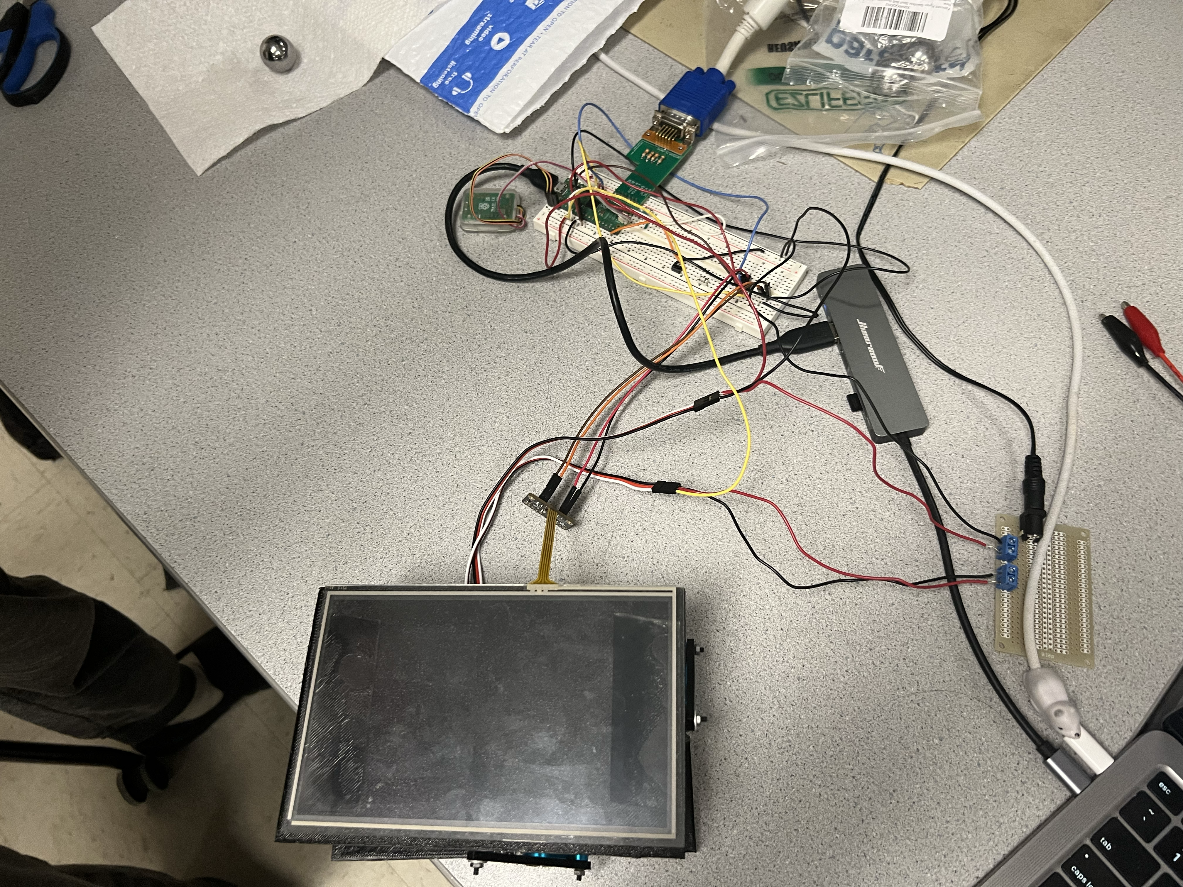
The touchscreen is wired so we can drive one pair of opposite edges and sense the voltage on the other pair. By switching between X and Y configurations and reading the Pico ADC, we sample the ball position a few hundred times per second. Each reading is averaged over 16 samples to reduce noise, then mapped into a normalized 0 to 100 coordinate system for each axis. Because we use a metal bearing ball, the contact with the touchscreen stays consistent, which helps keep the ADC readings stable.
On the RP2040 we use several protothreads. A balance thread runs the PID controller and updates the servos. A serial thread prints the current state for debugging. The VGA code runs in the main loop and uses PIO and DMA to drive a 640×480 display. This structure lets the time critical control work run at a fixed rate while the display and printing run in the background.
High Level Design
Background math
Touchscreen readings are converted from raw ADC counts into normalized coordinates using a linear map:
x = (Vx − Vx_min) / (Vx_max − Vx_min) · 100
y = (Vy − Vy_min) / (Vy_max − Vy_min) · 100
where Vx_min, Vx_max, Vy_min, and Vy_max are the calibration extremes when the ball is moved to the edges of the plate. The target point is at (50, 50). For each axis the error is e = setpoint − position and we apply a PID controller
u = Kp · e + Ki · integral(e) + Kd · derivative(e)
The PID outputs for X and Y are interpreted as tilt commands, then added to the neutral servo pulse width. In our final design, 1500 µs is the neutral value that holds the plate close to level. Values approaching 1700 µs tilt in one direction, while values near 1300 µs tilt in the opposite direction. These bounds are enforced in software so the plate cannot hit the frame.
Program/hardware design
Program details
The main software modules are the touchscreen sampler, the PID controller, the servo PWM driver, the VGA graphics functions, and a serial debug thread. Touchscreen sampling uses a repeating timer that alternates between X and Y modes, takes several ADC readings per axis, and stores averaged values. The balance thread checks for new samples, converts them to normalized coordinates, and calls the PID update for each axis.
The PID function tracks the current error, the integral of error, and the change in error for each axis. We clamp the integral term to avoid windup and keep the derivative term within a reasonable range so noise does not cause large corrections. The output is an offset in microseconds that we add to the neutral pulse width. Servo commands are then clamped to the safe range of 1300 µs to 1700 µs.
PWM is generated using a single RP2040 PWM slice configured at 50 Hz. We set the wrap value and clock divider so one count equals one microsecond. This lets us write pulse widths directly in microseconds using a helper function. The two servos use the A and B channels of the same slice, which keeps their timing in sync.
VGA display and logical structure
The VGA driver is based on the course RP2040 VGA code. It uses PIO to generate horizontal and vertical sync and RGB output, and DMA to stream a packed 4 bit pixel buffer to the monitor. On top of that we wrote drawing routines for lines, rectangles, text, and a filled circle used for the ball marker.
The display shows a small plot window in the upper left corner. The ball appears as a 6 pixel circle whose position is set by the normalized 0 to 100 coordinates. Below the plot, a horizontal bar shows the X axis servo command, and a vertical bar on the right shows the Y axis servo command. Markers at 1500 µs indicate the neutral points. We only redraw the plot region each frame, which keeps VGA overhead low and lets the control loop keep a steady rate.
Hardware details

3D Design
Components
The core hardware is the Raspberry Pi Pico which we have used in the lab throughout the semester, various buttons and wires were also used to connect components and control the program. The VGA adapter from Lab 2 was also used to facilitate the VGA graphics UI.
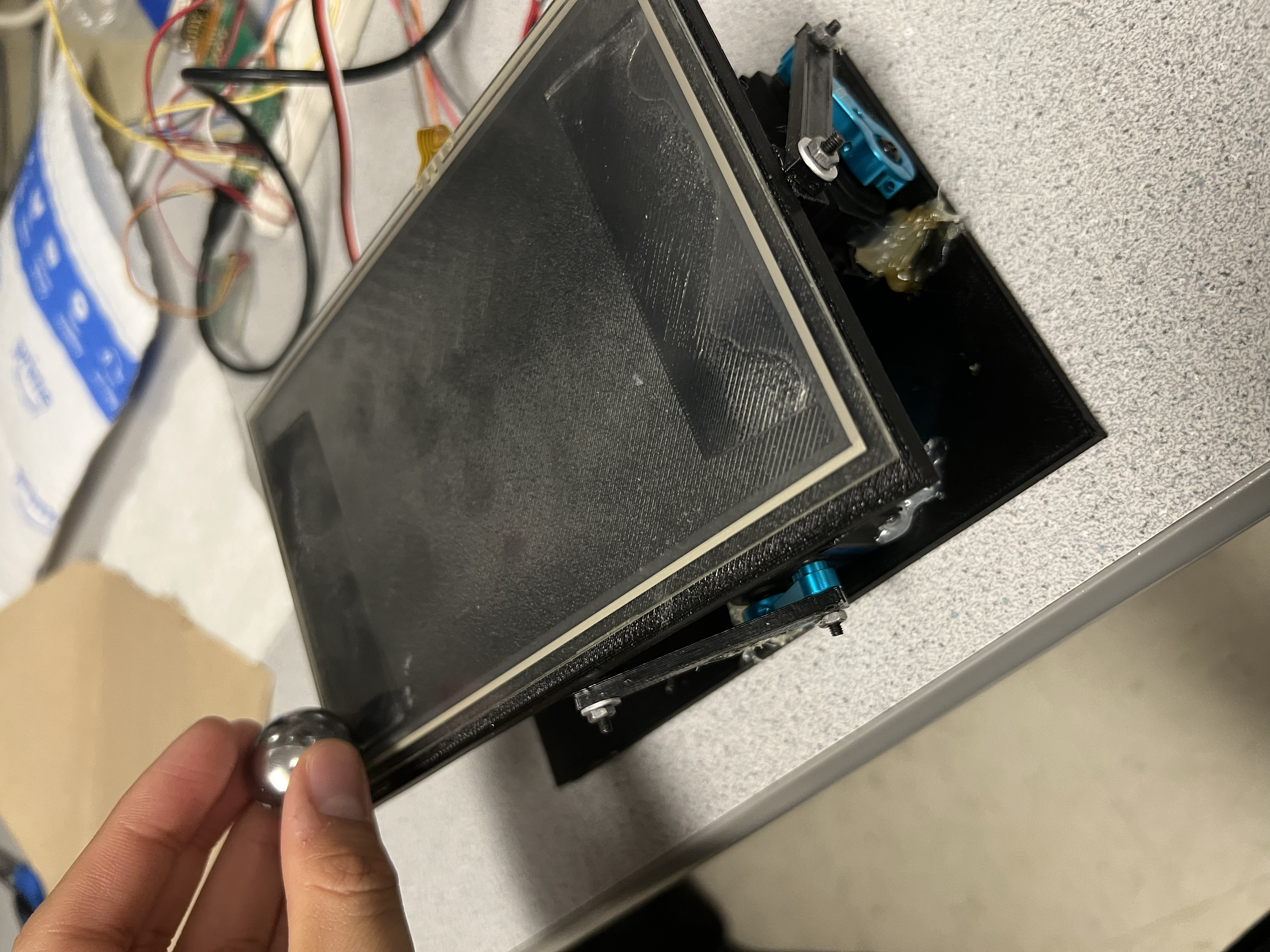
Servos are connected to PWM capable pins and powered from a separate 5 V supply, with all grounds tied together. The plate is mounted on a ball joint at its center, which allows tilt in both axes. Each servo connects to the plate through a 3D printed linkage near the edge, roughly aligned with the X or Y axis. This layout makes each servo mainly responsible for one axis and reduces coupling. A simple frame holds the plate, ball joint, and servos, and gives enough clearance so the plate can tilt without hitting the base.
Our main sensor was an adafruit 105mm by 165mm resistive touchscreen, the touchscreen has 4 pins, X-, X+, Y-, and Y+. By driving the X- pin to ground and leaving the X+ pin floating, Y+ can be measured using an ADC pin on the pico, the opposite can be done to measure X+, driving Y- to ground and leaving Y+ floating. This was done using a timer tied to an interrupt that would toggle between measuring X and Y, allowing us to get a very fast measurement of the touchscreen. However, there were many issues with the touchscreen itself. First and foremost, the bottom left of the touchscreen was not correctly measuring position. There seemed to be an issue with the hardware such that measurements made in that corner were measured to be closer to the center than they actually were. Furthermore, the measurements gathered appeared to be slightly different every time the program was run. This is especially problematic for our project, which needs precise and accurate measurements, and the resistive touchscreen was not accurate in the bottom left corner, and was not precise ever. Furthermore there were very strange issues which lead to the X and Y measurements appearing to be positively correlated, such that an increase in the X measurement would lead to an increase in the Y measurement, even if the actual Y level was not changing. This was fixed by having the measurement logic take a dummy measurement with the ADC read. This dummy measurement would be unused, and a second measurement would be taken and assigned to a variable to be used. This seemingly fixed our issue and we did not see anything similar happen again.
Things that did not work at first
At first we tried to run the controller using raw touchscreen readings with almost no averaging. The ball position jumped and the PID controller produced noisy servo commands that shook the plate. Adding averaging over 16 samples per axis and limiting the derivative term removed most of this jitter. We also tried higher gains to get faster response, but that gave oscillations and overshoot. After several rounds of tuning we settled on moderate gains that gave a good balance between speed and stability.
At first we also had issues with the centering of the ball. As mentioned before, whenever power was cycled the measurements would change, such that the exact same point would occasionally measure with a difference of up to 20%. To combat this instead of having a hard coded “center”, which is what we started with. A button was added to transition between a pause state and an unpaused state. During the pause state, the servos would be reset to their default position, which is a PWM of 1500us, during the transition from the paused state to the unpaused state, the touchscreen would take a snapshot of the current measured position and treat that as the center that the ball would be returned to.
AI use
We used AI tools such as ChatGPT to review background topics like PID tuning and VGA timing, and to clean up small code snippets we had already written. We did not paste large AI generated code blocks directly into our project. All of the code that runs on the RP2040 for control, touchscreen reading, servo driving, and plotting was written and debugged by us and tested on the hardware.
Results of the design
We tested the system by placing the ball at different starting points on the plate and watching both the physical motion and the VGA display. For moderate disturbances the ball moved toward the center and settled in roughly one second. Because we use a metal bearing ball that stays in contact with the touchscreen, the position readings stayed consistent and there were no jumps from the ball leaving the surface.

Results Visualization
The control loop ran at about 350 Hz, while touchscreen sampling ran at about 500 Hz to support averaging. Servo updates followed the standard 50 Hz rate. With the VGA driver running from DMA and PIO, the CPU had enough time to keep the control loop stable. After we moved large drawing operations out of the time critical path there was no visible flicker on the display.
After calibration, the ball stayed within a few millimeters of the plate center at steady state. On the VGA plot this appeared as a small cluster of points around the setpoint. The resolution is limited by the touchscreen and ADC quantization, but it is good enough for smooth control and a clear visual demonstration. We checked PWM timing on an oscilloscope and confirmed that the signals met the expected deadlines.
Safety was enforced by clamping servo commands and by limiting the physical travel of the linkage. Even when gains were set too high during tuning, the plate could not tilt far enough to hit the frame. The system runs from low voltage supplies and the wiring is secured to reduce the chance of shorts. During normal use a user can place the ball anywhere on the plate without risk to the hardware since the ball does not bounce or fly off the surface.
From a usability point of view, the system is simple to operate. After power up, the plate levels and the VGA display shows the current ball position. A user can move the ball and watch it roll back toward the center while the plot and servo bars update in real time. This makes the project a useful demonstration of feedback control for students and visitors in the lab.
Conclusions
Overall, the ball balancing robot somewhat met our main design goals. The system keeps the ball near the center of the plate for typical disturbances, and the VGA display gives clear insight into how the controller responds. However, we were plagued with various hardware issues, the mechanical construction of the plate was not rigid, and the plate the ball was balanced on could be moved without the servos moving. This was due to the screws we used to connect the servos to the top plate getting loose and allowing the entire assembly to wiggle. Using a form of threadlocker would mitigate this issue. Furthermore the issues we encountered with the resistive touchscreen as described above compounded on this issue, making very precise PID control extremely difficult if not impossible with our setup. Various attempts were made to alleviate some of the hardware issues with software. A scaling factor was added to combat the inaccurate bottom left corner, but it was quickly found that the inaccuracy was not linear and impossible to cleanly fix without taking an extremely large amount of data and analyzing it, which we did not have time for. Any large deviations from the center would inevitably result in failure.
If we repeated this project, we would consider using faster or higher torque servos and a stiffer mechanical frame to improve response to larger disturbances. We might also add an IMU or other sensor to measure plate tilt directly and compare it with the inferred tilt from servo PWM. Having a better and more accurate resistive touchscreen would also improve the system a lot. This would allow more advanced control laws and better modeling of the system dynamics.
Our design follows common embedded system practices. Servo PWM uses standard 50 Hz timing. The VGA driver follows the 640×480 at 60 Hz standard. All communication and wiring follow low voltage safety guidelines used in the lab. For intellectual property, we used the course RP2040 VGA and protothreads libraries, which are provided for student use, and wrote the rest of the code ourselves. We did not sign non disclosure agreements, did not reverse engineer any product, and did not use code under restrictive licenses. The project could be turned into a low cost teaching kit, but we did not pursue any patent work.
Appendix A (permissions)
The group approves this report for inclusion on the course website.
The group approves the video for inclusion on the course youtube channel.
Additional appendices
Parts List
- Raspberry Pi Pico (RP2040) – Class provided
- Adafruit 4-wire resistive touchscreen (105mm × 165mm) – $15.00
- Steel bearing ball – $5.00
- SunFounder hobby servos (2×) – $45.00
- 3D printed linkage + frame components – Class provided
- Wires, connectors, fasteners, acrylic plate materials – Lab provided
- External 5V supply for servos – Lab provided
References
Key documentation and course resources used in this project:
RP2040 DatasheetRaspberry Pi Pico C/C++ SDK Documentation
Adafruit Resistive Touchscreen Overview
ECE 4760 Course Page
Hunter Adams RP2040 Demos (VGA/PIO examples)
Bootstrap (v3) Documentation
Code Appendix
Below is the main RP2040 C source used for touchscreen sampling, PID control, servo PWM output, and VGA plotting. The full project archive includes all required headers and support files.
      #include <stdio.h>
      #include <stdlib.h>
      #include <math.h>
      #include <string.h>

      #include "pico/stdlib.h"
      #include "pico/multicore.h"

      #include "hardware/pwm.h"
      #include "hardware/irq.h"
      #include "hardware/adc.h"
      #include "hardware/clocks.h"

      #include "pt_cornell_rp2040_v1_4.h"
      #include "vga16_graphics_v2.h"

      // ============================================================
      // ------------------------ SERVO SETUP ------------------------
      // ============================================================

      #define PWM_OUT_1 4   // Servo X
      #define PWM_OUT_2 5   // Servo Y

      // Regular hobby servo period = 20ms = 50Hz
      #define SERVO_FREQ 50.0
      #define WRAPVAL 19999             // counts for 50Hz at clkdiv=1 (20k cycles)
      #define CLKDIV   150.0            // 125 MHz / 125 = 1 MHz timer tick

      #define SERVO_MINX 1100             // microseconds
      #define SERVO_MAXX 1900            // microseconds
      #define SERVO_MINY 1100             // microseconds
      #define SERVO_MAXY 1900            // microseconds
      #define SERVO_NEUTRALX 1500
      #define SERVO_NEUTRALY 1520

      uint slice_num;

      // Convert µs → PWM level (µs * (ticks_per_us))
      static inline uint us_to_level(int us) { return us; }

      // ============================================================
      // ------------------------ TOUCHSCREEN ------------------------
      // ============================================================

      #define XMINUS 6
      #define YPLUS 7
      #define XPLUS 8
      #define YMINUS 9

      #define PIN_BUTTON 14

      volatile int TARGETX = 50;
      volatile int TARGETY = 50;

      volatile int chooser = 0;
      volatile uint adc_x_raw;
      volatile uint adc_y_raw;

      volatile int temp_p;
      volatile int temp_i;
      volatile int temp_d;
      volatile int display_px;
      volatile int display_ix;
      volatile int display_dx;
      volatile int display_py;
      volatile int display_iy;
      volatile int display_dy;


      volatile uint xarray[16];
      volatile uint yarray[16];

      volatile int xret, yret;
      volatile int latest_x = 0, latest_y = 0;
      volatile bool new_sample = false;
      unsigned char xpointer = 0;
      unsigned char ypointer = 0;

      volatile int scaled_x;
      volatile int scaled_y;
      volatile int servo_x;
      volatile int servo_y;

      volatile int phase = 0;
      volatile bool pause = true;
      volatile int debouncer_state = 0;

      volatile int counter = 0;

      // ===== Global PID term displays =====
      float p_term_x = 0, i_term_x = 0, d_term_x = 0;
      float p_term_y = 0, i_term_y = 0, d_term_y = 0;

      float kp_x = 8.0, ki_x = 0, kd_x = 1;
      float kp_y = 5.0, ki_y = 0, kd_y = 1;

      float err_int_x = 0, err_prev_x = 0;
      float err_int_y = 0, err_prev_y = 0;

      int PID_update(int target, int meas, float *err_i, float *err_p, float kp, float ki, float kd, bool y_fix)
      {
          float err = target - meas;
          if(!pause) {
              *err_i += err;
          } else {
              *err_i = 0;
          }
          float d = err - *err_p;
          *err_p = err;
          temp_p = kp*err;
          temp_i = ki*(*err_i);
          temp_d = kd*d;

          float output = temp_p + temp_i + temp_d;
          if(y_fix && output > 0) {
              temp_p = 2 * temp_p;
              temp_i = 2 * temp_i;
              temp_d = 2 * temp_d;
              return(int)(2 * output);
          }
          return (int)output;
      }

      void setupY(void) {
          gpio_set_dir(XMINUS, GPIO_OUT);
          gpio_set_dir(XPLUS, GPIO_OUT);
          gpio_set_dir(YPLUS, GPIO_IN);
          gpio_set_dir(YMINUS, GPIO_IN);
          gpio_put(XMINUS, 0);
          gpio_put(XPLUS, 1);
      }
      void setupX(void) {
          gpio_set_dir(XMINUS, GPIO_IN);
          gpio_set_dir(XPLUS, GPIO_IN);
          gpio_set_dir(YPLUS, GPIO_OUT);
          gpio_set_dir(YMINUS, GPIO_OUT);
          gpio_put(YMINUS, 0);
          gpio_put(YPLUS, 1);
      }

      bool repeating_timer_callback(struct repeating_timer *t) {
          if (chooser == 1) {
              setupX();
              adc_select_input(0);
              adc_read(); adc_read(); adc_read();
              adc_x_raw = adc_read();
              xarray[xpointer & 0x0F] = adc_x_raw;
              uint sum = 0;
              for (int i = 0; i < 8; i++) sum += xarray[i];
              xret = sum >> 3;
              xpointer++;
              chooser = 0;
          } else {
              setupY();
              adc_select_input(1);
              adc_read(); adc_read(); adc_read();
              adc_y_raw = adc_read();
              yarray[ypointer & 0x0F] = adc_y_raw;
              uint sum = 0;
              for (int i = 0; i < 8; i++) sum += yarray[i];
              yret = sum >> 3;
              ypointer++;
              chooser = 1;
          }

          latest_x = xret;
          latest_y = yret;

          latest_x = xret;
          latest_y = yret;

          // === 2. Scale touchscreen values ===
          int sx = (latest_x - 300) * 100 / (3600 - 300);
          int sy = (latest_y - 600) * 100 / (2000 - 0);

          if (sx < 0) sx = 0; if (sx > 100) sx = 100;
          if (sy < 0) sy = 0; if (sy > 100) sy = 100;

          scaled_x = 100 - sx;
          scaled_y = 100 - sy;
          bool at_left_edge   = (scaled_x <= 5);
          bool at_right_edge  = (scaled_x >= 95);
          bool at_bottom_edge = (scaled_y <= 5);
          bool at_top_edge    = (scaled_y >= 95);

          bool at_edge = at_left_edge || at_right_edge || at_bottom_edge || at_top_edge;
          bool at_corner = (at_left_edge || at_right_edge) && (at_top_edge || at_bottom_edge);
          // === 3. PID ===
          int targetx = TARGETX;
          int targety = TARGETY;

          int out_x = PID_update(targetx, scaled_x, &err_int_x, &err_prev_x, kp_x, ki_x, kd_x, false);
          display_px = temp_p;
          display_ix = temp_i;
          display_dx = temp_d;

          int out_y = PID_update(targety, scaled_y, &err_int_y, &err_prev_y, kp_y, ki_y, kd_y, false);
          display_py = temp_p;
          display_iy = temp_i;
          display_dy = temp_d;
          // Soften controller near edges/corners so servo does not slam
          if (at_corner) {
              // Very gentle when ball is in a corner
              out_x /= 2;   // half strength
              out_y /= 2;
          } else if (at_edge) {
              // Slightly softer on edges
              out_x = (out_x * 3) / 4;   // 75% strength
              out_y = (out_y * 3) / 4;
          }
          int sx_out, sy_out;

          if (pause) {
              sx_out = SERVO_NEUTRALX;
              sy_out = SERVO_NEUTRALY;
          } else {
              sx_out = SERVO_NEUTRALX + out_x;
              sy_out = SERVO_NEUTRALY + out_y;
          }

          if (sx_out < SERVO_MINX) sx_out = SERVO_MINX;
          if (sx_out > SERVO_MAXX) sx_out = SERVO_MAXX;
          if (sy_out < SERVO_MINY) sy_out = SERVO_MINY;
          if (sy_out > SERVO_MAXY) sy_out = SERVO_MAXY;

          servo_x = sx_out;
          servo_y = sy_out;

          pwm_set_chan_level(slice_num, PWM_CHAN_A, us_to_level(servo_x));
          pwm_set_chan_level(slice_num, PWM_CHAN_B, us_to_level(servo_y));

          new_sample = true;
          return true;
      }

      // ============================================================
      // --------------------- SERVO UPDATE THREAD -------------------
      // ============================================================

      static PT_THREAD(protothread_balance(struct pt *pt))
      {
          PT_BEGIN(pt);

          while (1) {
              switch(debouncer_state) {
                  case 0: {
                  if (gpio_get(PIN_BUTTON) == 0) {
                      debouncer_state = 1;
                      } else {
                      debouncer_state = 0;
                      }
                  break;
                  }
                  case 1: {
                  if (gpio_get(PIN_BUTTON) == 0) {
                      debouncer_state = 2;
                      if (pause == false) {
                          pause = true;
                      } else {
                          pause = false;
                          TARGETX = scaled_x;
                          TARGETY = scaled_y;
                      }
                  } else {
                      debouncer_state = 1;
                  }
                  break;
                  }
                  case 2: {
                  if (gpio_get(PIN_BUTTON) == 0) {
                      debouncer_state = 2;
                  } else {
                      debouncer_state = 3;
                  }
                  break;
                  }
                  case 3: {
                  if (gpio_get(PIN_BUTTON) == 0) {
                      debouncer_state = 2;
                  } else {
                      debouncer_state = 0;
                  }
                  break;
              }
              }

              counter = counter + 1;
              if(counter > 0) {
                  plotXY(scaled_x, scaled_y, WHITE, 0);
                  drawServoOutput(servo_x, WHITE, GREEN, 0);
                  drawServoOutputVertical(servo_y, WHITE, RED, 0);
                  fillRect(206, 10, 450, 88, BLACK);
                  setCursor(216, 10);
                  setTextSize(1);
                  setTextColor(WHITE);
                  char prop_information[100];
                  sprintf(prop_information, "Proportional Term (kp_x = %4.1f, kp_y = %4.1f), X:%d, Y:%d", kp_x, kp_y, display_px, display_py);
                  writeString(prop_information);

                  setCursor(216, 20);
                  char int_information[100];
                  sprintf(int_information, "Integral Term (ki_x = %4.1f, ki_y = %4.1f): X:%d, Y:%d", ki_x, ki_y, display_ix, display_iy);
                  writeString(int_information);

                  setCursor(216, 30);
                  char der_information[100];
                  sprintf(der_information, "Derivative Term (kd_x = %4.1f, kd_y = %4.1f): X:%d, Y:%d", kd_x, kd_y, display_dx, display_dy);
                  writeString(der_information);

                  setCursor(216, 40);
                  char servox_information[100];
                  sprintf(servox_information, "X Servo output (us): %d", servo_x);
                  writeString(servox_information);
                  setCursor(216, 50);
                  char servoy_information[100];
                  sprintf(servox_information, "Y Servo output (us): %d", servo_y);
                  writeString(servox_information);

                  setCursor(216, 60);
                  char pause_information[100];
                  if(pause) {
                      sprintf(pause_information, "Paused");
                  } else {
                      sprintf(pause_information, "Unpaused");
                  }
                  writeString(pause_information);

                  setCursor(216, 70);
                  char pos_information[100];
                  sprintf(servox_information, "Ball position: (%d, %d)", scaled_x, scaled_y);
                  writeString(servox_information);
                  setCursor(216, 80);
                  char target_information[100];
                  sprintf(servox_information, "Target position: (%d, %d)", TARGETX, TARGETY);
                  writeString(servox_information);
                  counter = 0;
              }

              PT_YIELD_usec(20000);
          }

          PT_END(pt);
      }

      // ============================================================
      // --------------------- SERIAL THREAD -------------------
      // ============================================================

      static PT_THREAD (protothread_serial(struct pt *pt))
      {
          PT_BEGIN(pt) ;
          static char classifier ;
          static int test_in ;
          static float float_in ;
          while(1) {
              sprintf(pt_serial_out_buffer, "X=%d Y=%d  servoX=%d servoY=%d\\r\\n",
                          pause, scaled_y, servo_x, servo_y);
              serial_write ;
          }
          PT_END(pt) ;
      }

      // ============================================================
      // ---------------------------- MAIN ---------------------------
      // ============================================================

      int main() {
          set_sys_clock_khz(150000, true) ;
          stdio_init_all();
          uart_init(uart0, 115200);
          gpio_set_function(0, GPIO_FUNC_UART);
          gpio_set_function(1, GPIO_FUNC_UART);

          initVGA();

          // ----- ADC -----
          adc_init();
          adc_gpio_init(26);
          adc_gpio_init(27);

          gpio_init(XMINUS); gpio_init(YPLUS);
          gpio_init(XPLUS);  gpio_init(YMINUS);
          gpio_init(PIN_BUTTON);
          gpio_set_dir(PIN_BUTTON, GPIO_IN);
          gpio_pull_up(PIN_BUTTON);

          // Timer for touchscreen
          struct repeating_timer timer;
          add_repeating_timer_us(-2500, repeating_timer_callback, NULL, &timer);

          // ----- SERVO PWM -----
          gpio_set_function(PWM_OUT_1, GPIO_FUNC_PWM);
          gpio_set_function(PWM_OUT_2, GPIO_FUNC_PWM);

          slice_num = pwm_gpio_to_slice_num(PWM_OUT_1);

          pwm_set_wrap(slice_num, WRAPVAL);
          pwm_set_clkdiv(slice_num, CLKDIV);

          pwm_set_chan_level(slice_num, PWM_CHAN_A, us_to_level(SERVO_NEUTRALX));
          pwm_set_chan_level(slice_num, PWM_CHAN_B, us_to_level(SERVO_NEUTRALY));
          pwm_set_mask_enabled(1u << slice_num);

          // ----- THREADS -----
          pt_add_thread(protothread_balance);
          pt_add_thread(protothread_serial) ;
          pt_schedule_start;

          return 0;
      }