High-Level Design
High-Level Philosophy
- Components/programs need not be bug-free or fully featured, as long as they are easily usable and capture the essence of what we are going for
- Apps are designed to show off features rather than be full-on experiences in of themselves
- Shortcuts and assumptions are made all throughout development to maximize development speed, as long as they don't cause glaring issues
- Things may be hard-coded or not made as modular as possible if doing so makes development speed faster
Background
Bluetooth
Bluetooth is a communication protocol that enables electronics within a close range to talk to each other. It is a ubiquitous, universal protocol that has seen mass adoption and implementation. The Raspberry Pi Pico W contains a bluetooth module, making it capable of connecting to other bluetooth devices. When used normally, the Wiimote uses Bluetooth to communicate with the Wii console. More specifically, it uses Bluetooth Classic with the HID profile. There are two main ‘types’ of Bluetooth:
- Bluetooth Classic: Original Bluetooth algorithm, this works by maintaining a constant connection between devices, making it more suitable for high-bandwidth tasks at the cost of power consumption
- Bluetooth Low Energy (BLE): More optimized for intermittent data transfer, this works by staying in a ‘sleep’ mode unless packets need to be sent. It is more suitable for low-bandwidth tasks, but uses far less power over a given period of time compared to Bluetooth Classic
The two Bluetooth types have different intended use cases and so are not intercompatible at either a hardware or software level. Focusing on Bluetooth Classic, there are multiple ‘profiles’ one can use which dictate the semantics of the communication itself. Nintendo chose to use the HID profile. HID defines a 'host' and 'device' as the two parties involed in a connection. Here, the Pico W is the host, and the Wiimote is the device.
Wiimote
The Nintendo Wii is a game console released by Nintendo in 2006. Nintendo heavily optimized the Wii to be as intuitive and user-friendly as possible, and this design focus aggressively changed the form factor and utility of the Wii controller (Wiimote) compared to normal game controllers. To be more specific, the Wiimote is designed to be very easy to pick up and understand, resulting in no joysticks being present on the controller. Additionally, Nintendo designed the controller such that users could ‘point’ it at their TVs and have a pointer appear at that point specifically.
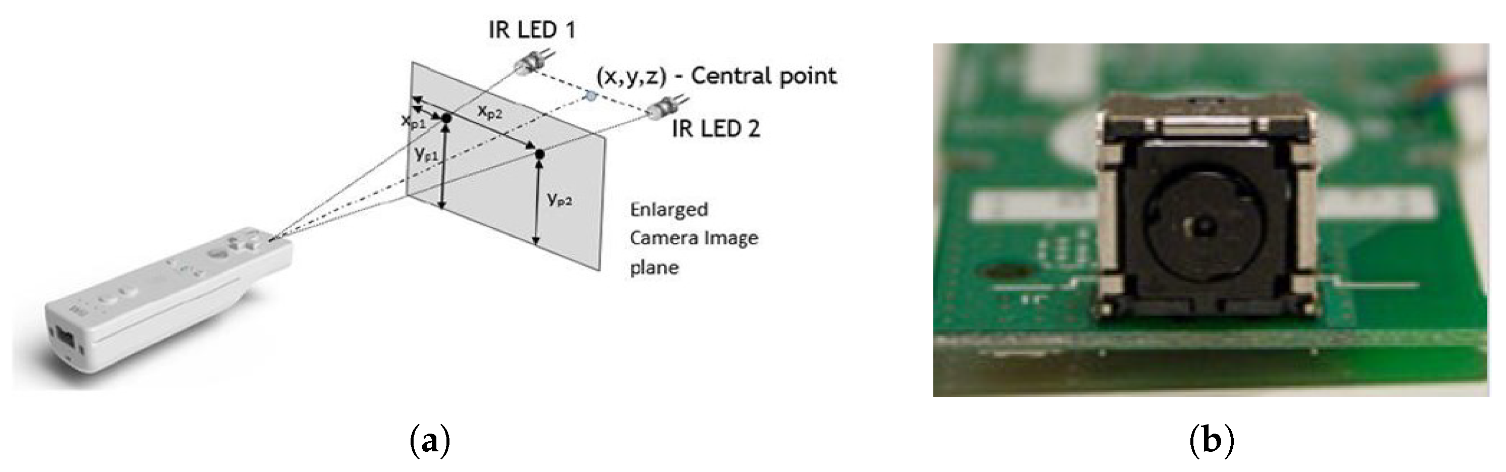
In order to pull this pointer off, Nintendo devised a system in which the Wiimote can pick up on IR sources that the user is required to place above their televisions upon setting up the Wii. In doing so, the Wiimote can roughly determine where it is in relation to the IR source, which can then be used to determine where the pointer should be drawn on screen; this is elaborated on further in the software and hardware sections.
Additionally, once a Bluetooth connection is established, the Wiimote will constantly send information to the host device. The Wiimote contains its core buttons, an IR camera, and an accelerometer; by default, the Wiimote will only send the core button statuses, but can be configured to send all information when possible. The message format that the Wiimote sends looks as follows (and is elaborated upon in the software section):
(a1) 33 BB BB AA AA AA II II II II II II II II II II II II
Logical Structure
For ease of development, we chose to split this project across two cores.
- Core 0: Handles establishing and maintaining the Bluetooth connection to the Wiimote
- Core 1: Handles all else (game logic, VGA display maintainence)
In theory, this project could have been done on one core due to the interrupt-based nature of the Bluetooth packets. We chose to split this into 2 cores anyways simply because we have the resources available and doing so prevents the possibility of timing issues contaminating the Bluetooth connection.
Legal Concerns
Hardware Design
The hardware component of this project is not particularly intensive in the sense that we didn’t need to invent anything, but there is still enough of note that a discussion of some component is warranted, mainly because an understanding of the hardware helps to motivate many of our software decisions.
Wii Controller (Wiimote)
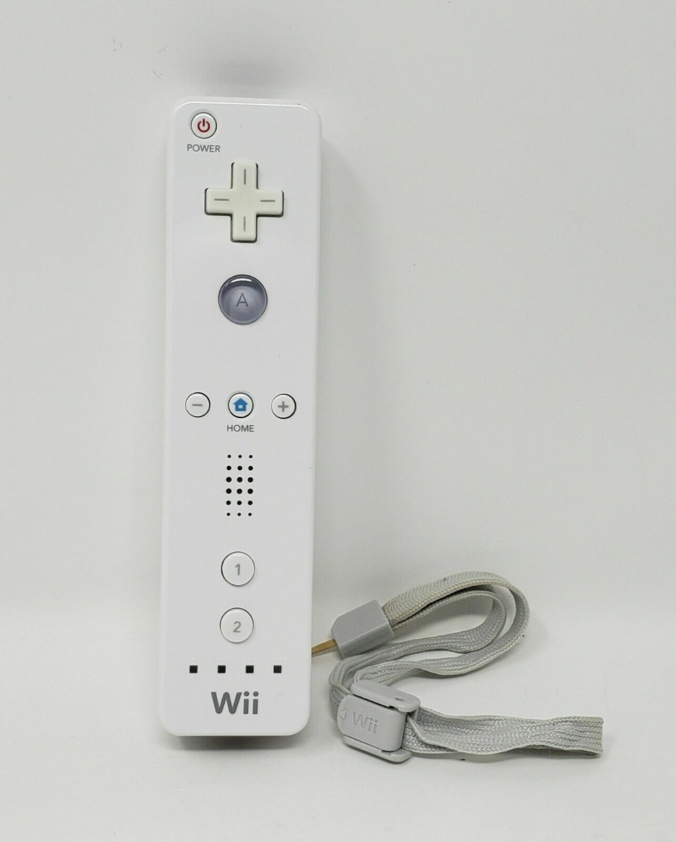
The controller we use for this project is a generic, used Wiimote that we bought off of Amazon. The Wiimote is, for all intents and purposes, a fully-running embedded system. It uses a Broadcom BCM2042 SOC, which provides core embedded functionality (a processor, RAM/ROM, etc.), expandability to peripherals, and a Bluetooth processor.
The BCM2042 is an off-the-shelf chip, pre-configured for the Bluetooth HID profile. Nintendo’s decision to use this SoC is one of the biggest reasons this project was possible, as it meant that issues surrounding proprietary software/hardware and reverse-engineering their would could be kept to a minimum. Furthermore, generic Bluetooth HID code for the Pico is plentiful, providing an easier platform to start software development upon.
Nintendo included a number of features on the Wiimote, which the BCM2042 treats as external peripherals. For this project, the ones of note are the buttons, accelerometer, and IR camera. There are a series of buttons across the Wiimote, and the Wiimote itself performs debouncing as button inputs are received. Nintendo included an ADXL330 accelerometer module on the Wiimote, which offers 3-axis acceleration data of the Wiimote. In our testing, the accelerometer was found to be pretty imprecise, and best utilized when ignoring directions and only using magnitude values (such as to pick up on actions such as swinging). Finally, Nintendo includes a 128*96 IR camera on the front of the unit. Discussion of this camera is covered in the software design section.
Wii Sensor Bar
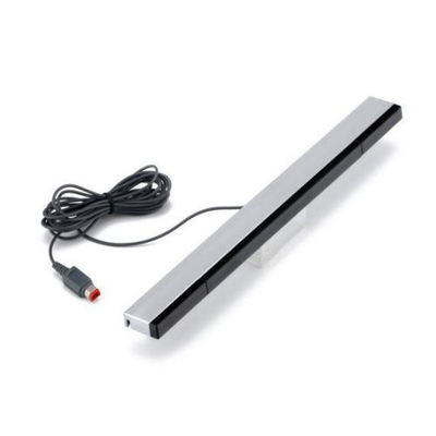
Every Wii came with a sensor bar, which customers were instructed to place at the top of their TVs. This ‘sensor bar’ is actually just a constant IR light source which the Wiimote’s IR camera can then pick up on; it plugs into the Wii purely for power. We purchased a very similar product which has a USB port for power (and not the proprietary connector Nintendo put on official Wii sensor bars) simply to maintain the theme of retrofitting Nintendo’s products. Technically though, any singular IR source placed atop the display would work as the Wiimote looks for and works with any arbitrary source of IR light in its environment.
VGA Printed Circuit Board
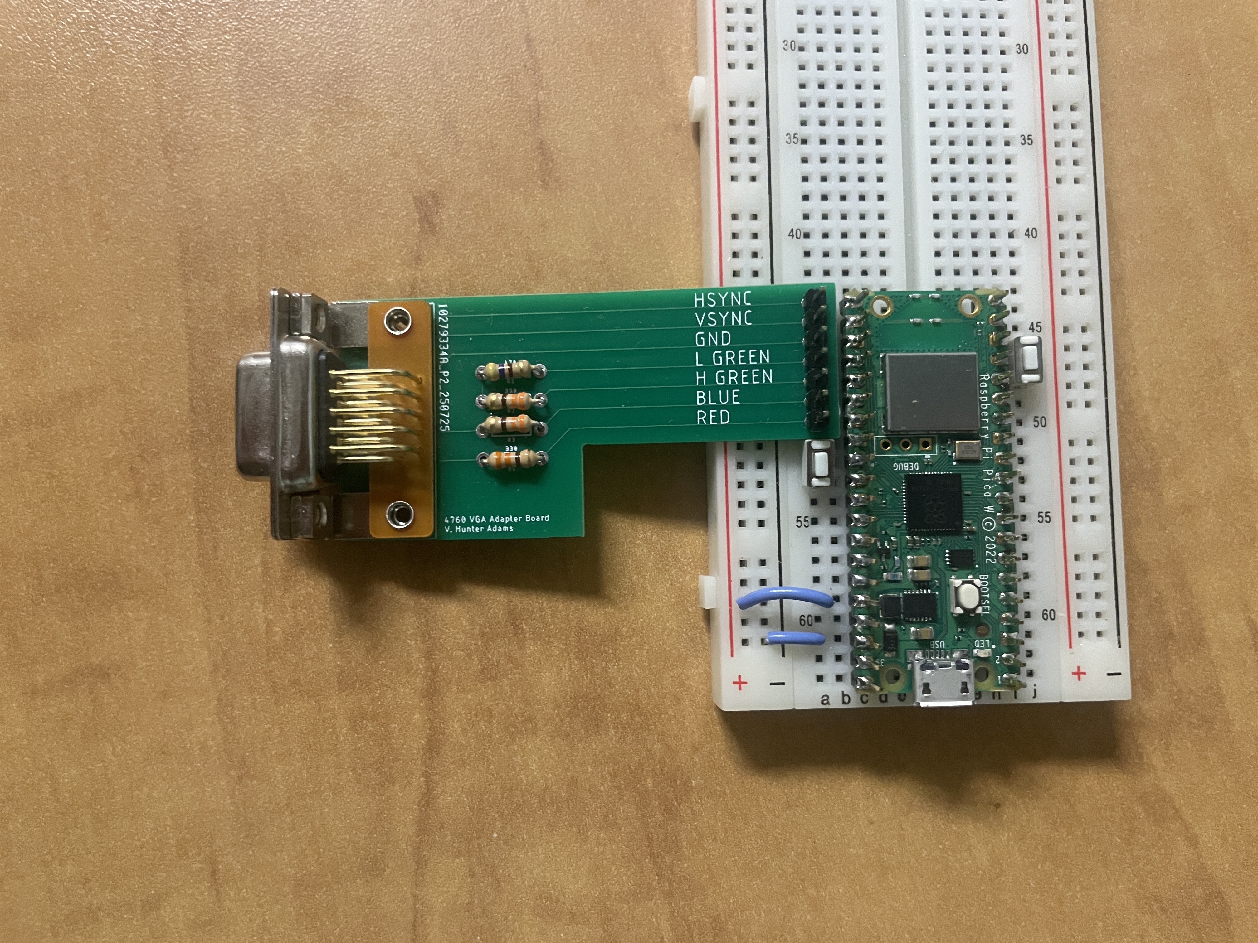
For this project, a custom VGA PCB (designed by Prof. Hunter Adams) was utilized to make interfacing the Pico with a VGA cable possible. The Pico is generating a slew of signals on 6 GPIO pins, each corresponding to a component of the VGA standard. The VSync and HSync pins are required to help stabilize on-screen elements. Notably, there are 4 color inputs - Red, Blue, HGreen, and LGreen. A provided VGA library includes functionality for displaying up to 16 different colors. As for the resistors present on the board - the Pico outputs 3.3V on each GPIO, but the VGA standard expects up to 0.7V per pin. Displays contain a 70 Ohm resistor to ground on each pin, but that is not sufficient to fully step down the 3.3V signal, and so an additional 330 Ohm resistor must be attached to the Red, H Green, and Blue pins. A 470 Ohm resistor is used on the L Green pin in an effort to better modulate the color, as a higher resistance results in a lower resultant voltage (and thus, lower color intensity).
Software Design
The software component of this project was simultaneously intense and varied in nature. Through software, we needed to establish a connection to the Wiimote, create a bunch of games and technical demos, and have a way to efficiently interface the two. The mindset and theory behind each ‘component’ of our software is unique; as such, this section is divided into sections to help better motivate and clarify why we made the decisions that we did.
As this is implemented in a Raspberry Pi Pico W, it's important to note the internal components being used. 2 DMA channels are claimed by the VGA drivers, as well as 3 PIO state machines on block 0. BTStack will claim 2 DMA channels and 2 PIO state machines on block 1.
1. Connecting to the Wiimote
main.c
In main.c, we start our main app loop on core 1 and start the Bluetooth connection code on core 0. We utilize protothreads on core 1 simply so we could have a debug thread which prints out the controller message from the Wiimote onto the terminal. If not debugging, the only thread running is our graphics thread. In it (among the standard code for maintaining VGA timings), we perform 2 calls - one to draw_curr_app() (defined in app_state), and another to draw_pointer() (defined in pointer).
Both functions will be described further in their respective sections, but the high-level idea is that the main app will be drawn, and then the Wiimote pointer will always draw over it. The strict division of this task into 2 functions follows our design decision to make this code as modularizable as possible.
Bluetooth
In wiimote_bt.hcontains the code for connecting the Wiimote to the Pico W. The Wiimote uses Bluetooth Classic with the HID profile, meaning that we could copy generic Bluetooth HID host code for the Pico and retrofit it to work with the Wiimote. The BTstack library and Wiibrew wiki pages were utilized extensively to determine how to prepare the Pico itself, as well as how to properly communicate with the Wiimote.
The Pico is configured as the HID host and initiates a connection to a fixed, hard-coded Bluetooth address corresponding to the Wiimote. Upon connection, the system transitions through a structured initialization sequence implemented as a timed state machine, which configures the Wiimote’s IR camera, sensitivity registers, reporting mode, and status LEDs using a combination of standard HID output reports and Wiimote-specific register writes. This staged approach ensures that each configuration step completes before the next begins. Once initialized, the interrupt report handler decodes incoming HID reports in report mode, extracting button states, accelerometer data, and raw IR blob coordinates and mapping them directly into shared control variables used elsewhere in the system.
Of note is the 0x33 reporting mode that configures the Wiimote to send button data along with accelerometer and IR data.
2. Communicating with the Wiimote
Player Input
A total of 17 bytes of data are included within the packets reported by the Wiimote. Of those, 4 describe button data, 6 describe the accelerometer, and the remaining 12 are for the IR, though these aren't hard restrictions and sometimes data are found in unused sections of other location of the packet. The exact configurations of individual data bits are described on the Wiibrew page.
(a1) 33 BB BB AA AA AA II II II II II II II II II II II II
Our implementation did not use on the Wiimote are the power and sync buttons. The other buttons can be accessed, and pressing them on the Wiimote flips its corresponding bit in the report data, which is then updated in global variables located in controls.h.
The accelerometer data describes acceleration in three axes, where the acceleration is reported as approximately 0x80 when standing still. Raw accelerometer data is provided in controls.h.
The IR camera, which is initialized from the above protocol, sends unsigned x and y values that describe the sensor bar's position relative to the Wiimote. This is only two bytes, which allows for up to 4 IR objects to be tracked. The sensor bar has IR sources placed on either end, allowing for two blobs to be visible in most instances. Technically, there are many more, as there are multiple sources on either end. However, the IR camera is not particularly good, and so the sources become blobs that are tracked by the Wiimote. Practically, there is rarely a use case for more than 2 blobs. Up to 4 objects are tracked, likely due to potential noise sources during the initial release period of the Wii such as TV remotes. Our implementation disregards everything but the first IR blob that is reported, which is a fair assumption at most distances, if knowing the location of both sensors is not necessary.
Given the location of these blobs, a cursor, or pointer, can be developed. Since we're given the blob's relative location to the Wiimote, and by extension the user, a pointer could be made by reversing this value and translating it to fit a screen. The pointer then moves to the left if the Wiimote moves to the left, since the blob's relative location moves to the right. A circular pointer at this position can be drawn on top of any underlying graphics using
wiimote_pointer.h
Player Feedback
There are three main forms of player feedback available on the Wiimote, two of which are implemented:
LED lights are controlled via a report to 0x11. In our current implementation, this is only ever called once, when a connection is established between the Wiimote and Pico W, though expanding its uses would be trivial.
Rumble is unique in that any report can update its value. The dedicated report ID is 0x10, which allows the Pico to toggle its rumble either on or off. However, since all reports, including steps in the IR camera initializations and LED light updates can alter this value, special care must be given to make sure that all outgoing reports have a consistent rumble bit. Rumble can be toggled on or off via bluetooth_rumble(bool).
The speaker on the Wiimote was not implemented here, as it fell out of scope of what we were hoping to achieve and would have added considerable complexity to our final project.
3. Graphics
Graphics are implemented alongside VGA driver code, all of which was provided (and mostly unedited) by Hunter Adams and Bruce Land. The option to draw in both 2-D and 3-D were provided. Some explanation is needed on how the 3-D code works, alongside adjustments to its original form. While the 2-D drawing pipeline is relatively straightforward, some additional explanation is warranted for the 3-D system and the modifications we made to better support interactive applications.
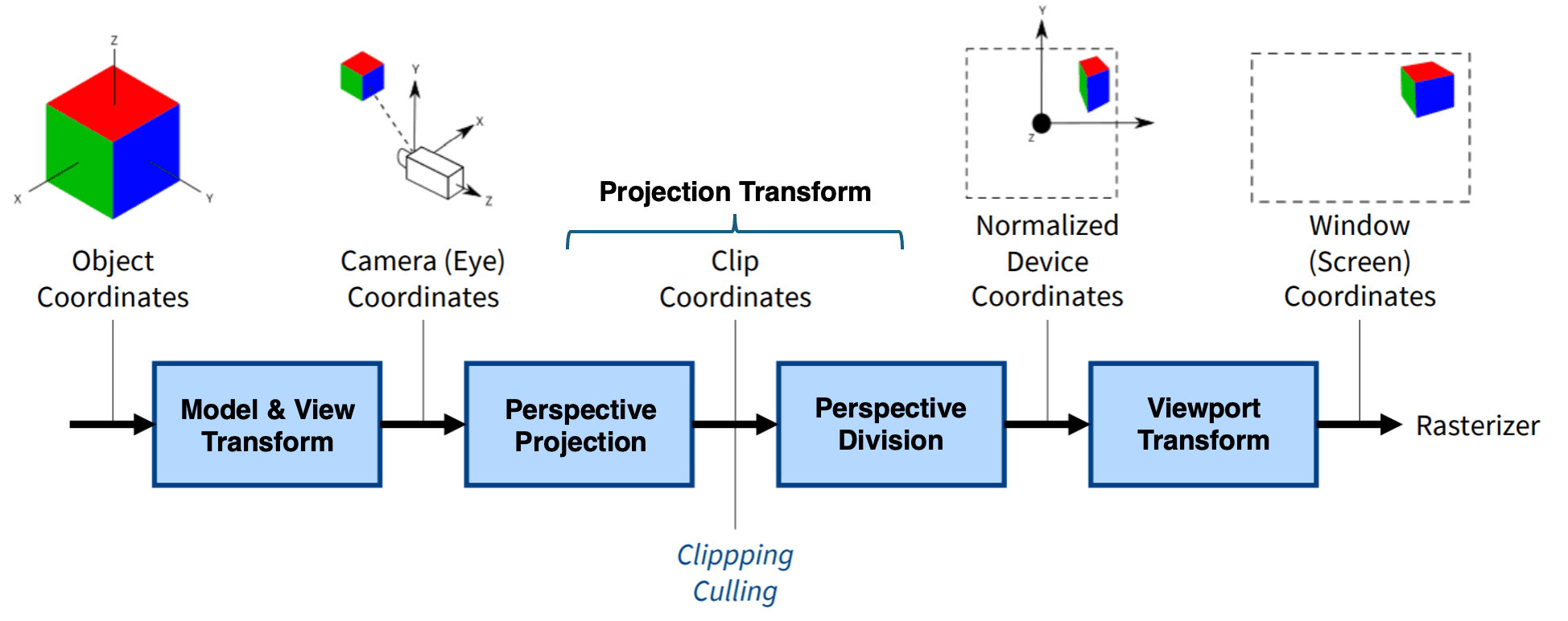
Transformations
Objects in a 3-D space have a number of options for reference frames, which require us to take advantage of matrix calculations. Given a location, transformations can be described as matrix multiplications on a vector.The transformation pipeline follows the standard sequence of model, view, and projection matrices. The projection projection, in particular, can be thought of as describing a cameras position in a world space, such that if we'd like to implement a game from a certain camera's angle, we just need to translate a camera. The matrix arithmetic is present in the 3-D code, which was modified slightly to decouple the projection matrix from the given 3-D demo code such that it can translate the camera depending on user input.
4. Apps
In order to create apps efficiently, we created a library which generates basic elements which the Wiimote can interface with. These interactive elements are represented as simple geometric primitives (circles and rectangles) with associated states describing whether they are movable, clickable, or constrained to a single axis of motion. Each frame, the system performs explicit hit-testing between the Wiimote pointer and object geometry to determine selection, using distance-based checks for circles and axis-aligned bounds for rectangles. Dragging behavior is driven by the Wiimote’s A button and is modeled as a small state machine that cleanly distinguishes between object acquisition, active dragging, and release, with optional bounding logic to support sliders or constrained controls. Clicking behavior uses rising- and falling-edge detection on the A/B buttons to support both momentary and toggle-style interactions without repeated triggering. After the interaction state is updated, all objects are redrawn deterministically each frame, ensuring visual consistency without reliance on partial redraws or retained graphics state. This approach provides a clear, modular abstraction for Wiimote-based UI interaction.
When trying to figure out what to do with the Wiimote, we realized that the controller had so many features that it would have been difficult to come up with one singular app which shows them all off. Furthermore, we had a large number of ideas on what we wanted to actually implement. As such, it was decided that we should work on a number of lower-quality apps, rather than try to produce one very high-quality app.
We wanted for the user to dynamically switch between apps; to make this as simple to implement as possible, each app is required to have the following functions:
init_objs_APPNAME()draw_APPNAME()
The init_objs_APPNAME() function is explained as part of the game_primitives section. As for draw_APPNAME(), the idea is that this function will be run on a loop and be responsible for drawing the app elements. Apps can declare other local functions if they’d like, they just need to have these two functions. By developing and respecting this system, we could more freely develop apps without worry about how to integrate it later on.
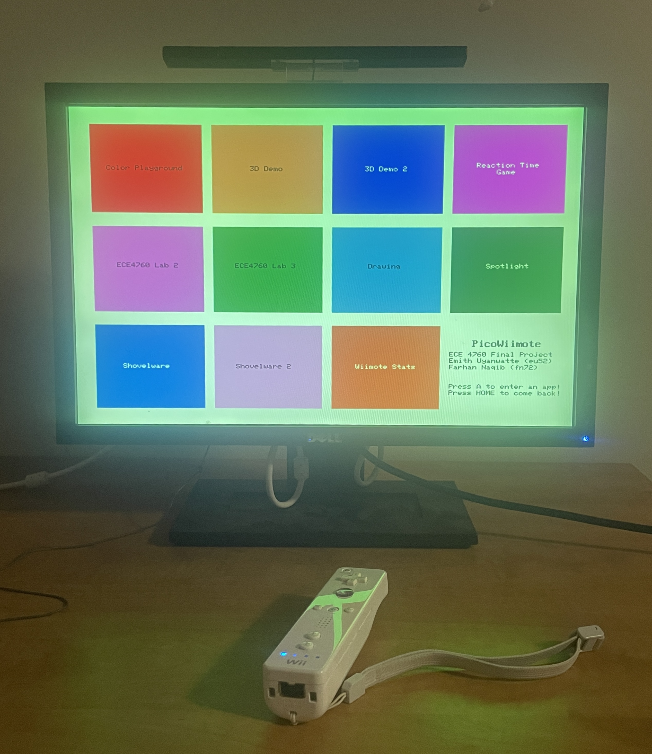
We developed 11 apps in total (10 visible on the main menu, and the main menu itself is also an app). What follows is a description of each app, with similar apps grouped into the same section:
Main Menu
The main menu of the software. Users can select another to open by holding their Wiimote on the app and pressing A.
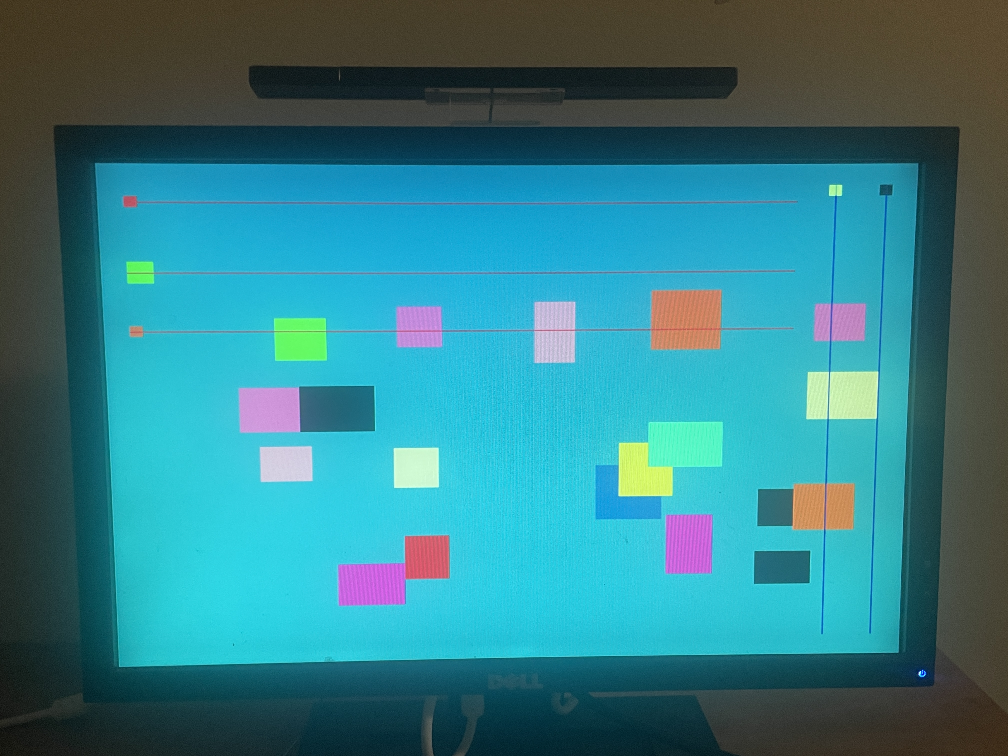
Color Playground
This app acted as an initial testing ground for our objects. Each of the objects have different logic depending on if they are clicked/pressed, and one button toggles the rumble if pressed.
3D Demo and 3D Demo 2
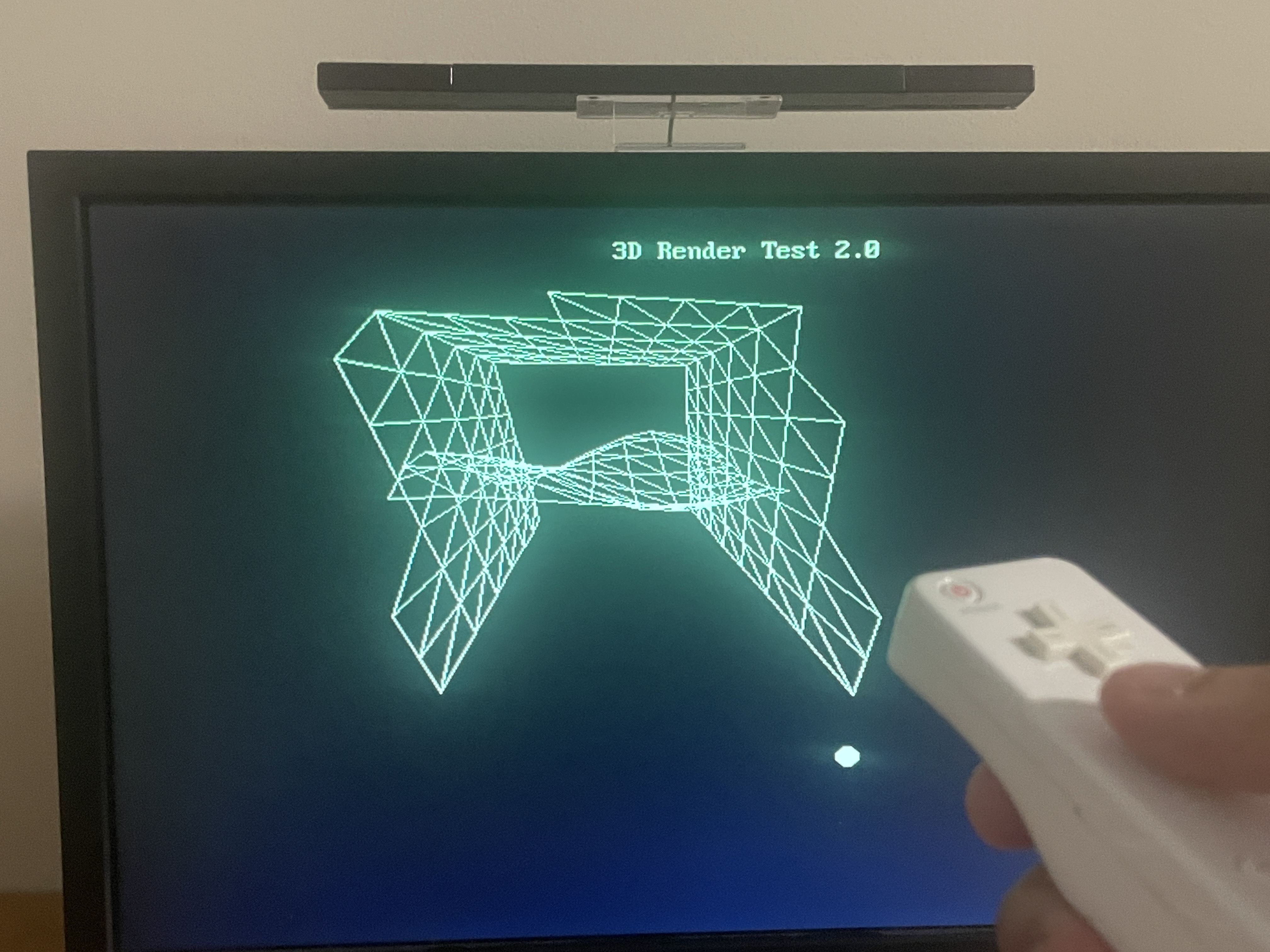
By using updated transformation matrices, 3-D scenes can be shown while the camera moves around either via d-pad input (Demo 1) or through the pointer (Demo 2). Accelerometer data is also used for Demo 2, where the magnitude of the Wiimote's acceleration is tracked, and when it exceeds a large threshold, it's processed as a swing, changing the amplitude of a sinusoidal mesh.
Drawing
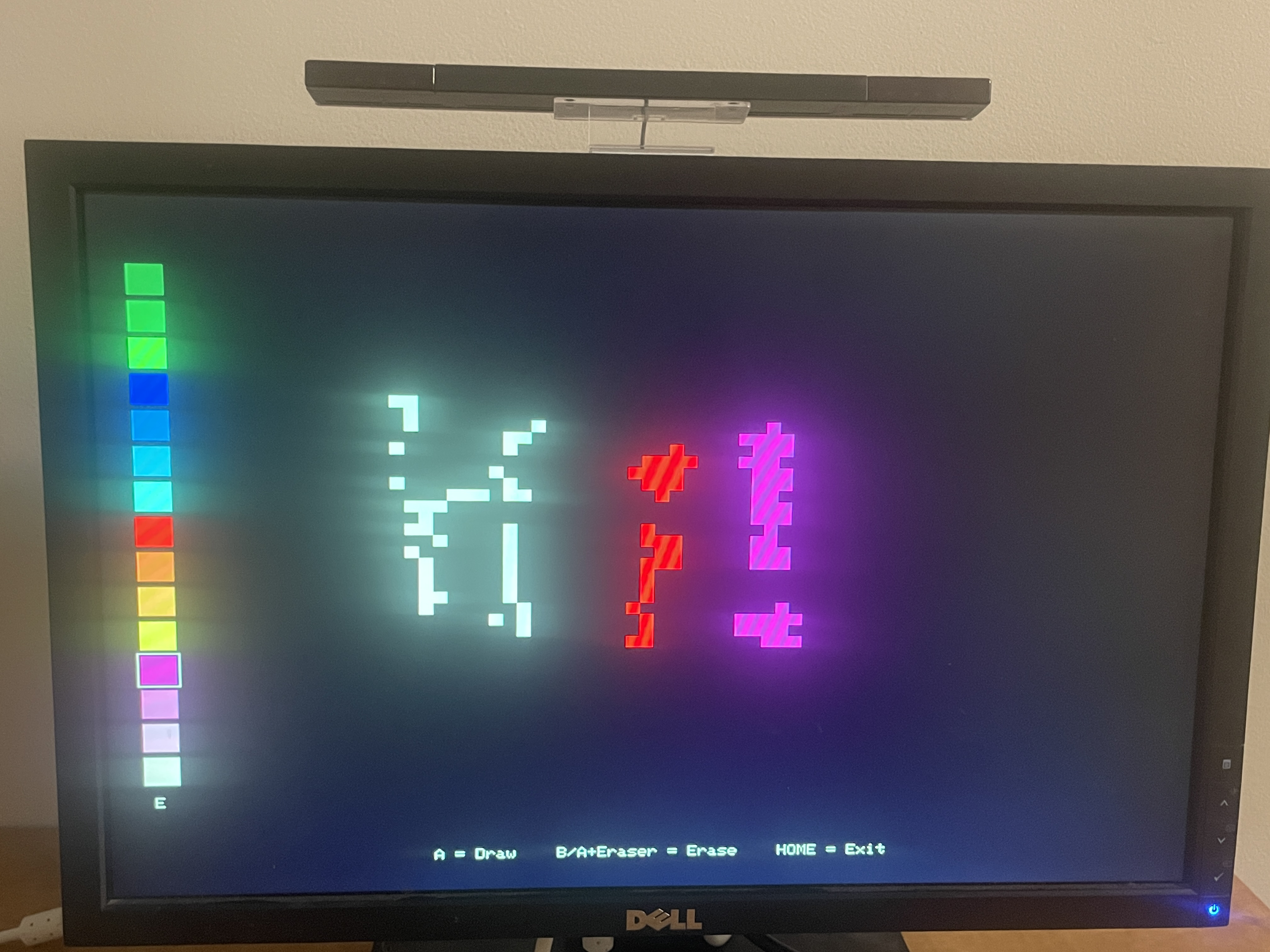
This is a drawing app where the user can select a color on the left of the screen, draw by holding the A button, and erase by holding the B button. It features a pixel-art aesthetic for the reasons that pixel-art was originally used (memory limitations) - there is far too little memory to store a buffer for every pixel, so pixel art is employed to reduce the total number of data that needs to be stored.
ECE4760 Lab 2
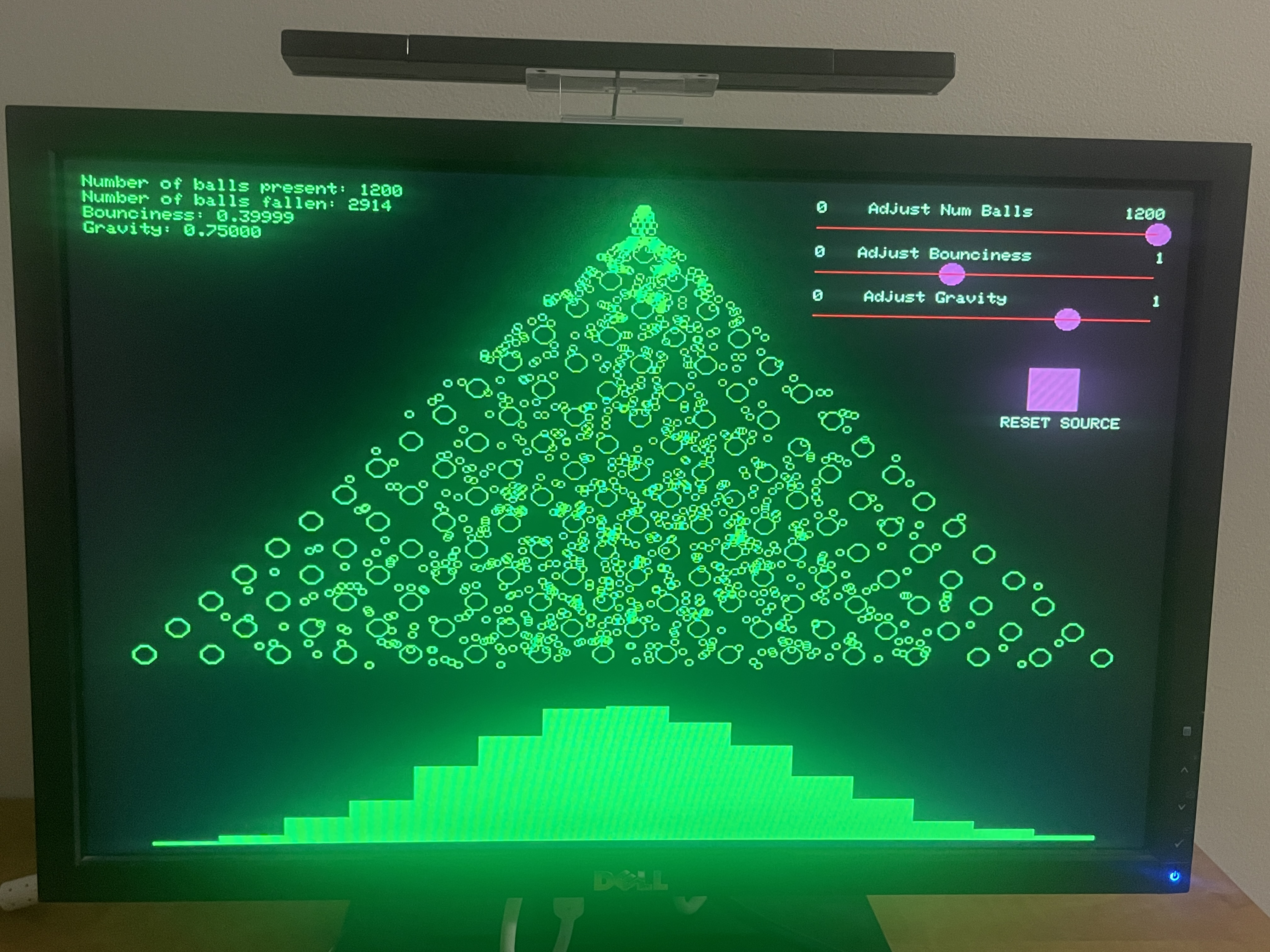
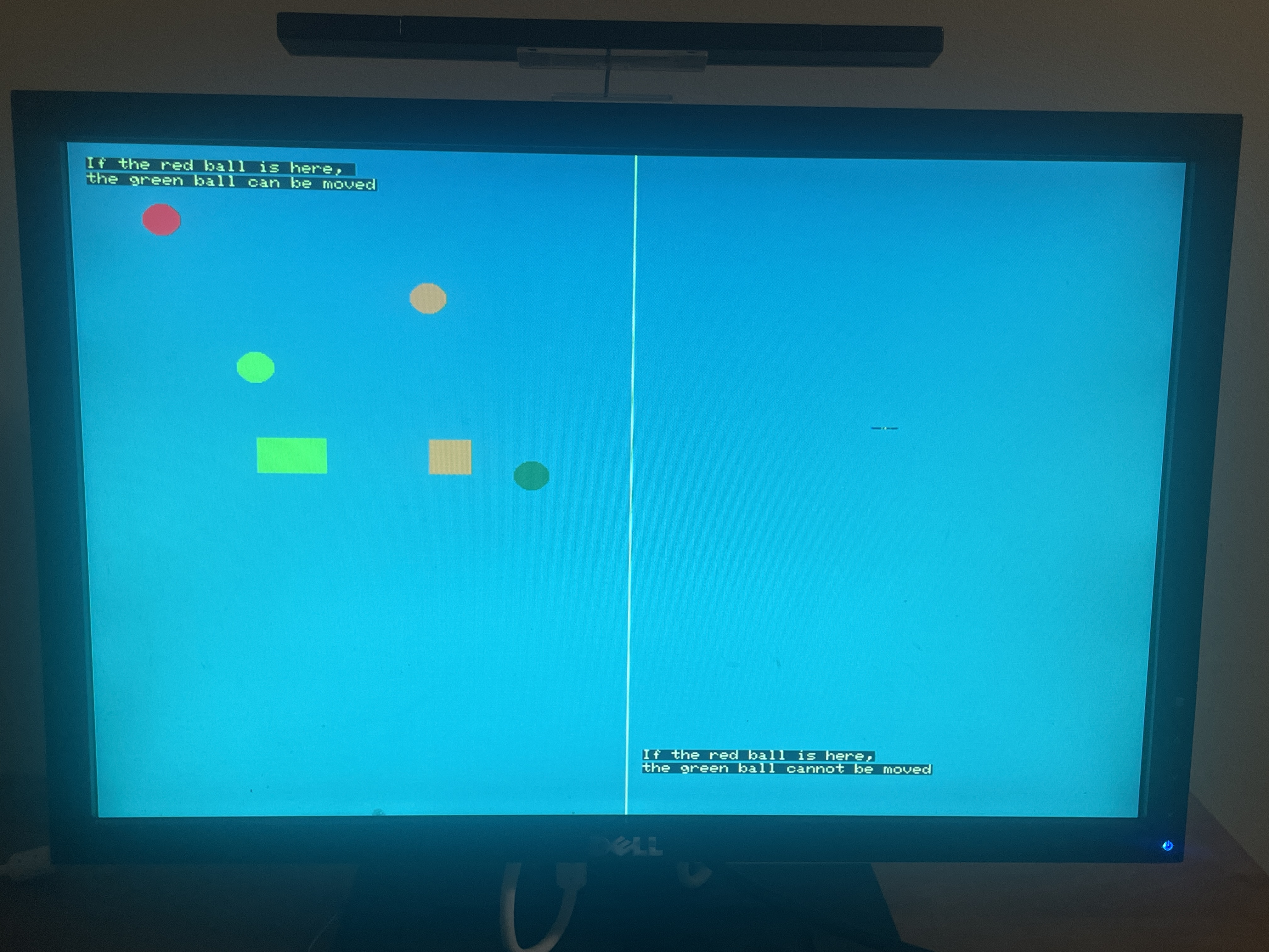
This is the ECE 4760 lab 2 code, slightly modified to be usable with a Wiimote. Users can use the sliders on the top left to change the number of balls present, the amount of gravity, or the bounciness of each ball. Users can also freely drag around the spawn point of the ball, and reset it back to it's initial position with the reset button.
Reaction Time Game
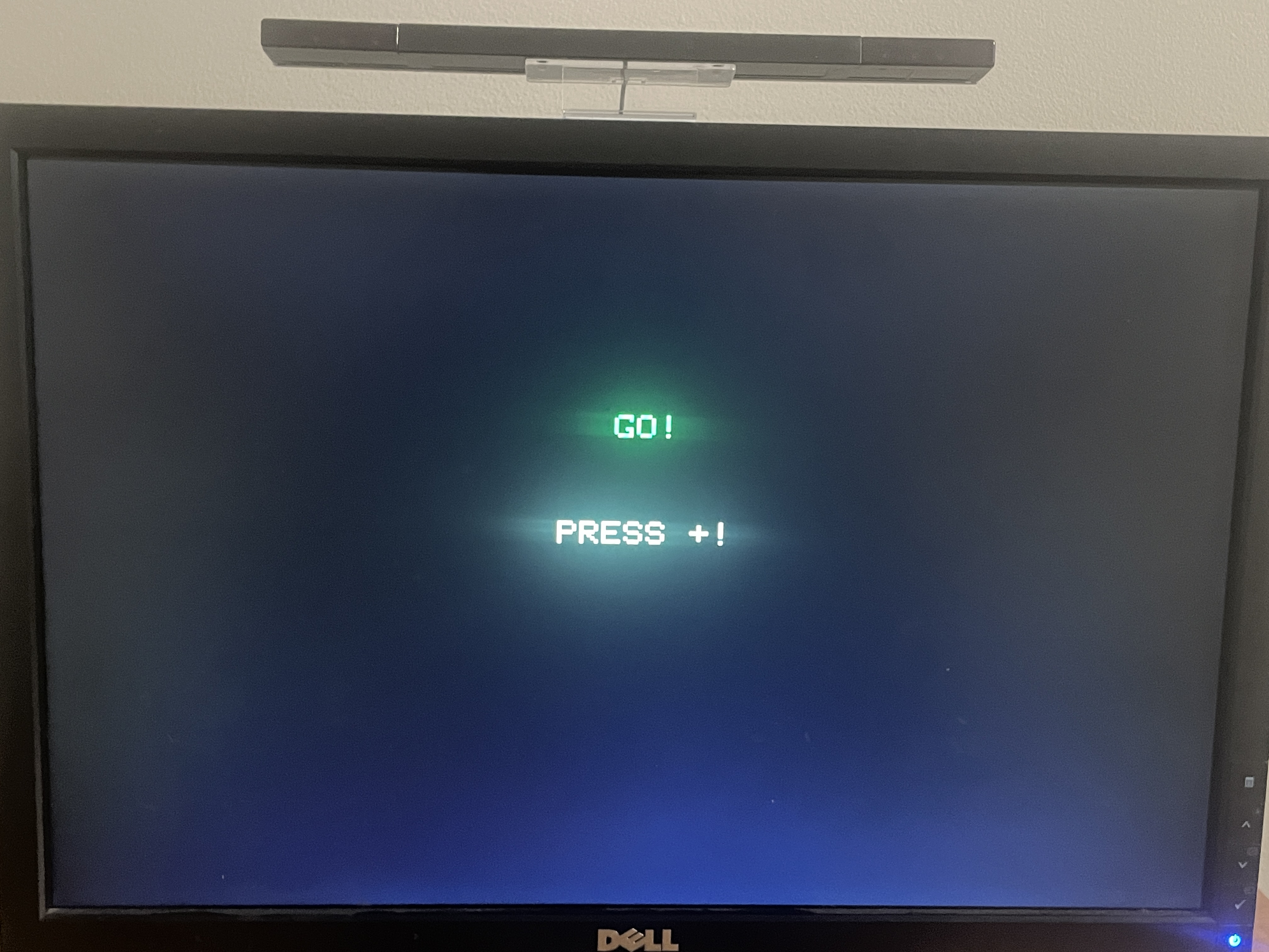
This is a reaction time game. Users are instructed to wait, until a random button appears on screen. If users press the button correctly, they are shown their reaction time in milliseconds. Otherwise, they are told that they failed.
Shovelware and Shovelware 2
This is another testing ground, this time to stress-test the Wiimote usable objects by randomly generating many objects. One is for circles, the other is for squares.
Spotlight
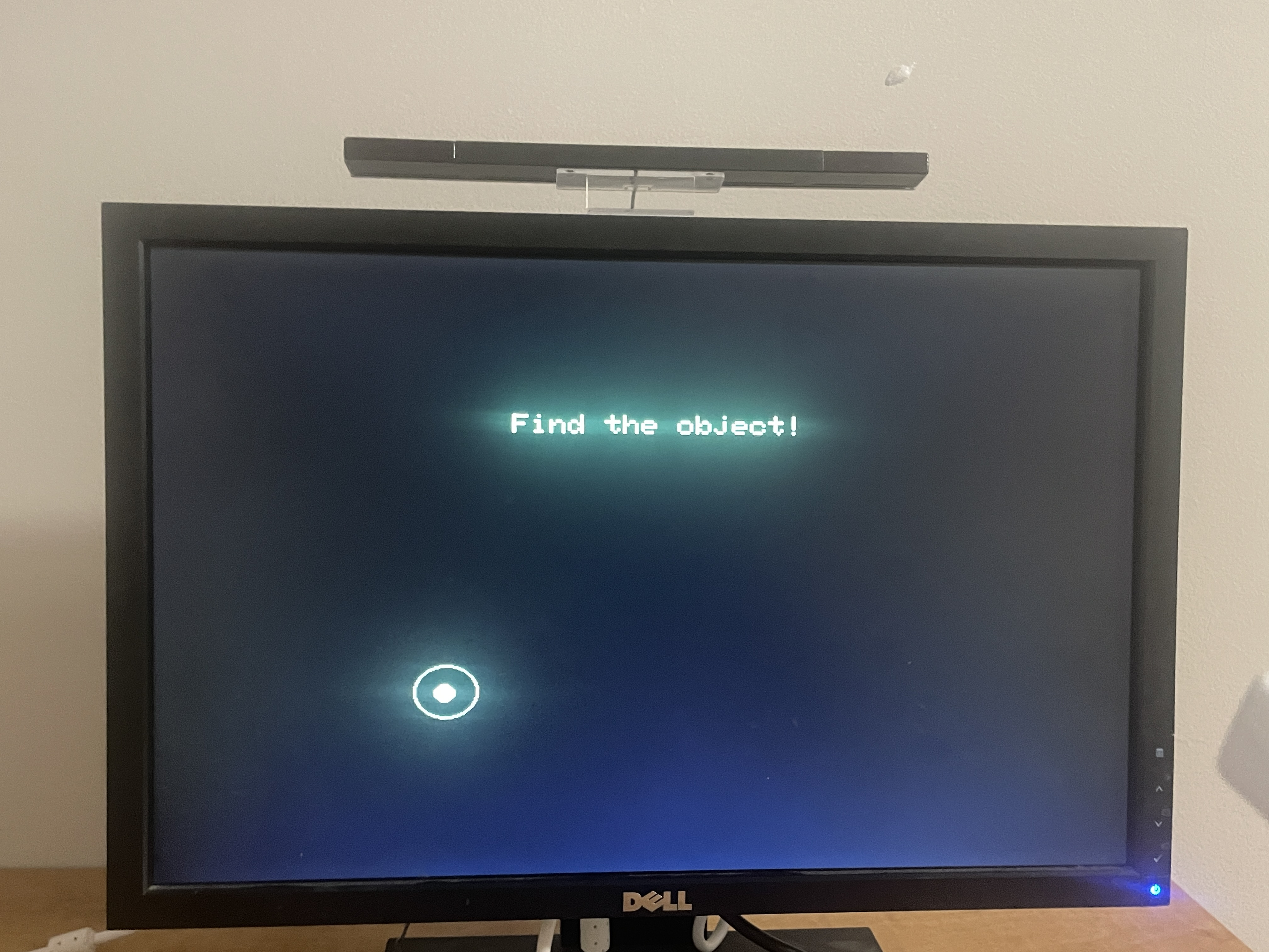
Users are instructed to drag the Wiimote around on screen until they find a 'hidden' object, after which they are told the time it took them to find the object.
Wiimote Stats
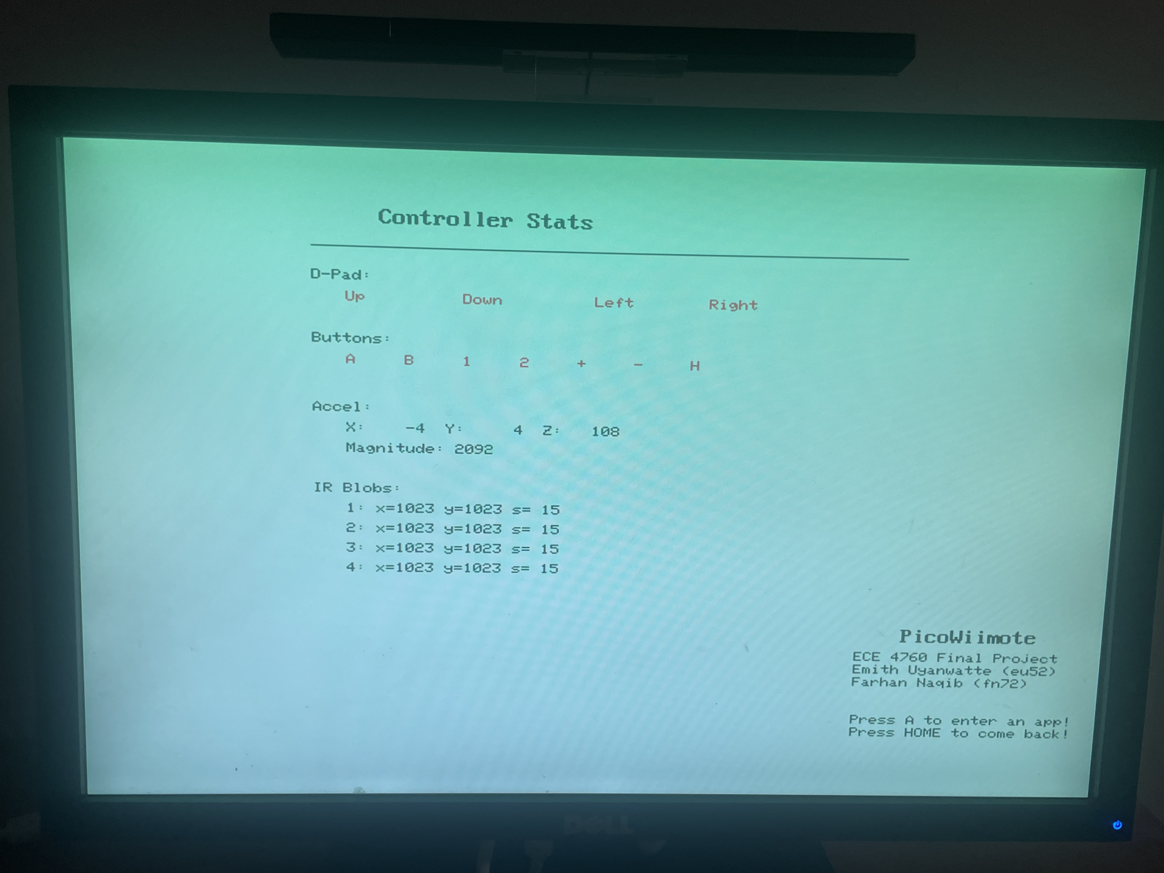
This displays wiimote information available in controls.h
5. App states and app switching
One of the hallmark features of this project is the ability to switch between apps seemingly seamlessly. In order to pull this off effectively, the program is performing numerous tasks in the background, many of which (by design) go completely unnoticed by the user.
App State Machine
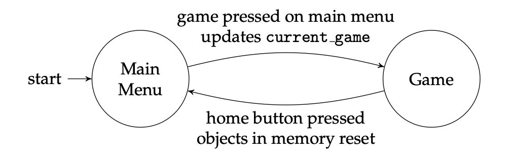
The Pico will always start on the main menu. Users can open an app by selecting it, and then go back to the main menu by pressing the Home button. That behavior can roughly be modeled by the presented state machine - Game is meant to represent any arbuitrary game.
Components of Game State
In the init_objs_APPNAME(); function, all apps are required to specify the following:
- Their main background color
- The color of the Wiimote pointer
- Any and all Wiimote-interactable objects
Furthermore, memory-heavy apps (such as the 3D demos or Lab 2) are required to dynamically allocate their most memory-intensive components.
In the draw_APPNAME(); function, apps are required to have a check to see if home is pressed. If true, they must do the following:
- Kill all generated Wiimote objects with the provided kill_wiimote_objs() function
- Set the current game to MAIN_MENU
Furthermore, memory-heavy apps must free their allocated memory.
This all serves to boost the user experience.
- By declaring the main background color, the Wiimote pointer knows the most optimal color to replace old frames of itself with. This was very cheap for the RP2040 while still providing a good enough effect of erasing old frames that the user would not notice it too much.
- Because every app sets their own Wiimote color, the designer has the ability to set the color to one distinct from the main color pallet of the app, making for a less frustrating experience.
- By having apps declare their Wiimote objects at init, and clearing that array right before they exit, we could dramatically reduce the total amount of memory used by these Wiimote objects while giving each app the ability to have and use objects however they want.
- In our testing, crashes due to memory leaks only occured once a memory-heavy app without dynamic allocation was opened 7 or 8 times. That being said, it was frustrating enough that dynamic memory allocation was favored.
This is all to say, considerable thought has been put into optimizing around both the user experience and the limitations set by the RP2040.
Results
We implemented a Bluetooth Classic connection between a Nintendo Wii Remote and a Raspberry Pi Pico W, allowing us access to raw button, accelerometer, and IR camera data that can be decoded in real time, while requesting changes to the Wiimote's LED and rumble status. We then used those inputs to control multiple interactive VGA-based applications and games. There was no noticeable latency during pointer movement, dragging, or button interactions. Using both cores proved to be useful, as Bluetooth communication and graphics/game logic were able to run concurrently without any scheduling problems. The VGA output remained stable with no persistent flicker or tear.
The inputs transmitted in the bluetooth connection were surprisingly accurate for a device built two decades ago for a cheap, mass-produced video console system. Accelerometer data could accurately detect a swing, while IR-based pointing was consistent, if a little jittery. Still, testing from various users showed positive results, where they often indicated that the system was intuitive and easy to use, which was the original intention behind the design of the Wii system and its remote.
Design Tradeoffs: We omitted audio output from the final implementation, compared to what was originally proposed. This allowed additional development time to be spent on interaction logic and polishing the applications.
Conclusion
We were able to successfully produce what we proposed, and did so in a way that made it easily adaptable to existing code as well as code developed with it in mind. This acts as a strong foundation upon which further work can be done. As mentioned in our High-Level Philosophy, we did not take advantage of every single feature the Wiimote has. Given more time, these features would have been used in some way to make for a more impressive (and useful) final product.
In any case, a few of these features are listed below:
-
Speaker Implementation:
- The Wiimote has a speaker embedded into it, and can play sounds sent to it from the Bluetooth Host. We did not investigate this because we found that it was not integral to our core vision, but future work could make interesting use of this.
-
Writable memory on Wiimote:
- On official Wii consoles, users have the ability of saving their custom characters to their Wiimote, letting them bring their Wiimotes to other Wii consoles and carry their characters over. There are no actual restrictions on what can be written to this memory space, which can allow for state preservation between Pico resets or even between different Pico modules, among other things.
-
Wii MotionPlus (and other plug-in peripherals):
- On the bottom of the Wiimote is a port - Nintendo designed this such that any manufacturer can make a peripheral and have it work with the Wii just by plugging it in to the Wiimote. Getting the data stream of this peripheral on our codebase is as simple as changing one line of code. There are countless peripherals available - one of particular note is the Wii MotionPlus peripheral, which adds a gyroscope to the Wiimote. With an accelerometer and gyroscope, the Wiimote can now more accurately determine its own location in 3D space.
-
IR Blob size:
- We receive IR blob size information and even process it, but don’t use it in any meaningful way. This blob size gives a relative distance that the Wiimote is away from the sensor bar, providing more potentially useful data.
When developing this project, we ran into countless issues across every component. A few particularly interesting issues are as follows:
-
Memory issues:
- When switching between apps, we didn’t account for memory frees upon app quits, causing freezes whenever a particularly memory-heavy app is opened multiple times. We solved this by having the apps allocate their large memory chunks dynamically instead.
-
VGA flicker issues:
- In order to prevent the issue of pointer artifacts not being cleared, we originally had all non-pointer objects redraw themselves every frame. This resulted in a very clear flicker appearing whenever more than a few objects were drawn at once. This was resolved by refactoring the logic such that the background never had to be redrawn, but every other object did; this dramatically reduced the load of pixels which need to be redrawn on any given frame.
- Another more interesting issue we encountered was where the order in which things were drawn affected if they flickered or not. For example, if an object was drawn very low on the screen, then another very high on the screen in the same frame, this could cause a flicker. This was resolved simply by swapping the order in which objects were drawn.
-
Wiimote timing issues:
- Establishing the initial Bluetooth connection between the Wiimote and Pico was not too difficult thanks to the use of HID and the abundant resources available.
- The Wiimote is an embedded system, and so certain actions involve setting register values. One such action is enabling the IR camera, which we needed as the pointer was the real reason we were working with a Wiimote in the first place.
- Essentially all sources online seem to assume that you are working on a system with a full OS, which handles multithreading (and in particular, reading Wiimote packets) seamlessly.
- Writing to these register values mandates a ~50ms delay between sends, so the Wiimote has time to properly perform the operation.
- We originally implemented this delay using the inbuilt sleep(); function, which puts the full thread to sleep and prevents packets from being read.
- This resulted in error codes being received which were not documented anywhere, inconsistent behaviors between runs, and unrelated factors (such as LEDs on) being affected. This made it very hard to deduce what the core issue was.
- Endless guessing and checking, along with deductive reasoning, resulted in us getting the solution we have now.
Work Distribution
Emith Uyanwatte (eu52)
- Established connection between Wiimote and Pico W
- Calibrated pointer data to screen
- Created 2D Wiimote object library
- App development
Farhan Naqib (fn72)
- Decoded Wiimote data output
- Calibrated accelerometer data
- App development
Appendix A: Permissions
The group approves this report for inclusion on the course website.
The group approves the video for inclusion on the course youtube channel.
Appendix B: Commented Code
Please see our repo here: Github Link
Alternatively, the files could be donwnloaded directly from here:
Note that ECE 4760 Labs 2 and 3 code are redacted for academic integrity reasons!
Appendix C: Schematics
Please refer to Hardware Design section above.
Appendix D: Work Distribution
Please refer to Work Distribution section above.
References
Code/designs borrowed from others
- BTStack Repository
- ECE 4760 Lab 2 - Digital Galton Board
- ECE 4760 Lab 3 - PID Control of a 1D Helicoptor
- VGA Driver Code
- 3D Graphics Rendering Code