Final Project Report: SpectroTuner
Authors: Arielle Huang (aph74), Jack Chaney (jbc282)
Date: December 19, 2025
Course: ECE 4760
1. Project Introduction
The Sound Bite
Summary
We built an adjustable spectrogram and tuner because we wanted to be able to (for lack of better words) tune the pitch as well as the tone of an instrument. We thought that it would be possible to do this by showing the frequency spectrum of the instrument over time, while also allowing for traditional instrument tuning through a graphical interface.
2. High Level Design
Rationale and Sources
We thought it would be interesting to build a device that allows musicians to tune their instruments while also seeing a visualization of how their actions (changing effects, techniques, voicings, etc.) affect their tone. While there is not much immediate utility exposed through this, since music is for the ears, we expect that allowing artists another way to interpret their sound while configuring the media they perform through could spark creativity and encourage a deeper understanding of why things sound the way they do. This is because seeing a real-time spectral representation of one's sound makes it easy to see the patterns and shifts in harmonics as they change various parameters.
Background Math
On a high level, our project relies on two different mathematical processes: a Discrete-Time Fourier Transform and a Fundamental Frequency Recognition process. The essential functions of our project are a spectrogram and a visual tuning function that pulls data from the spectrogram to ascertain what note is coming from an input source. Both the spectrogram and tuner are highly adjustable, with the spectrogram allowing for variation of draw speed and input sensitivity, and the tuner allowing for variation of tuning reference (e.g. A = 440 Hz), as well as octave and note. The mathematical nature of the Fourier transform will be discussed in later sections, since the discrete code implementation does not immediately conceptualize a Fourier transform.
We perform a Discrete-Time Fourier Transform on the input from either the microphone or the line-in, which serves to provide us with information about the relative strengths of frequencies present in one time-step of the input. We use this information for plotting and tuning. The way that our tuning code works involves selecting the most prominent frequency in a time-step of the Fourier transform and checking if it is inside of a pre-computed 40-cent bounding box around the frequency dictated by the user's note choice. A cent is a musical unit, defined as one-hundredth of the frequency difference between two notes. The computation of the bounding boxes involves logarithms, since the human perception of audio is logarithmic with respect to pitch. This also means that musical notes get further apart in frequency in higher octaves, so our tuning indicators make larger jumps in frequency as higher octaves are selected for tuning.
Logical Structure

The logical structure of our project consists of four main blocks: sound input, signal processing, visualization, and parameter modification. The sound input is converted into a frequency mapping by the signal processing block, which is visualized according to user-selected parameters that are set by the parameter modification block. Each of these blocks consist of one or more threads running on the microcontroller.
Hardware/Software Tradeoffs
Some of the hardware trade offs we made in our design include worse part quality, since our ordered parts from Digikey did not arrive in time, and we needed to integrate the hardware to do final testing. Because of this, we settled for some lower quality hardware from the lab, including a cheaper microphone module than what we initially planned, that in theory would be slightly less well-suited for our application. We did not really have to make any major software trade offs, since the Raspberry Pi Pico's software tooling and Protothreads library allowed us to create all the functionality that we needed.
Existing IP
Our project does not appear to infringe upon any patents, copyrights, or trademarks.
3. Program/Hardware Design
Program Details
a. FFT/Spectrogram
The mathematically-heaviest part of our code is contained within the FFT protothread, which reads from the ADC using DMA, and uses this information as the source for an in-place FFT. The Cooley-Tukey FFT algorithm we used is the same as is included in the FFT demo in the ECE 4760 RP2040 Demos repository. The Cooley-Tukey algorithm works to reduce the computation required to calculate Discrete-Time Fourier Transforms by a massive amount (O(n2) vs. O(nlogn)) by breaking the operation into smaller and smaller groups of calculations, until only pairs of data points remain. Then, the algorithm leverages the symmetry inherent in Fourier Transforms to quickly calculate the magnitudes of each pair, before recombining every point back together to produce an array containing the transformed input. This implementation is also done in fixed-point arithmetic, which is generally much faster than floating point on the RP2040, since it doesn't have a dedicated FPU. The post-fft samples are then used to get the relative strengths of each frequency. The source of the FFT is determined by the source mode, which allows for different channels of the ADC to be read so that input can come from either the microphone or the line-in. The ADC FIFO is cleared before the FFT runs on a new source so that data corruption/false outputs do not happen. We primarily relied upon the RP2040 VGA driver provided earlier in the course for displaying to the VGA, but we did have to write our own code to allow the PIO state machines to function properly when the RP2040 was running at higher clock speeds. We pushed it to 250 MHz.

b. Inlined Functions
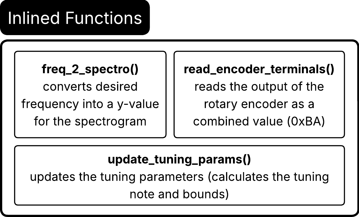
There are three inline functions that we implemented: freq_2_spectro(), read_encoder_terminals(), and update_tuning_params(). We implemented freq_2_spectro() to convert the fix15 frequency inputted to the function to a proportional y-value that will be displayed on the spectrogram. The implementation is essentially the inverse way of how the FFT puts the magnitudes into bins. In the FFT thread, each vertical time slice is drawn from the top down and the y-value that correlates to a bin of the FFT is retained within the for loop as variable i. In freq_2_spectro(), we compute the “i” or y-value with y = (SPECTRO_HEIGHT - 1) - (fix2int15(bin) << 1) which is the reverse of the FFT implementation. The value is then clamped to the lower and upper bounds of the spectrogram and returned.
As for read_encoder_terminals(), implementing a rotary encoder given the library we found was quite simple compared to attempting to use the potentiometer. We used this function to get a four bit packet, 0xBA, which held the encoded value of the two pins of the rotary encoder. We first store the two values of the corresponding GPIO pins, convert them to the inverted version since the signals are active low with pull-ups, and then return (a | ( b << 1)) & 0x3, which recovers 0xBA from the GPIO values A and B. This function is then used when determining if the rotary encoder is spun clockwise or counterclockwise.
The last inline function update_tuning_params() allows us to reset the tuning bounds and reset the graph easily throughout the program. To calculate the tuning bounds, we first get the base note that the user wants to tune to and then grab the desired octave to tune to. The function then recalculates the tuning note based on the octave ((base note * 2^(octave - 4)), we subtract 4 since the base note is in the fourth octave) and the center frequency by multiplying the note frequency at the desired octave by the ratio of the center frequency over 440Hz (correlates to the standard tuning reference frequency). This resulting tuning frequency is used to calculate the upper (multiplied by the cents_padding) and lower (divided by the cents_padding) bounds of the tuning frequency. The cents_padding depends on the number of cents, which is calculated by taking 2^(cents/1200). Typically, good tuning is based on +/-10 cents around the desired frequency, but to make the tuning more accessible for the average person's vocals and for the bounds to show up better on the display, we used +/-40 cents.
While testing the spectrogram, we noticed that the drawn tuning bounds would often overlap when displayed. This is mostly due to FFT frequency resolution and integer rounding when converting the calculated frequencies to pixel coordinates. A 20 to 40Hz cent offset around the notes is typically around the order of a few Hz (for C4, 261.63Hz with bounds of +/-20 cents the range is 6.04Hz), while the bin spacing (Fs/NUM_SAMPLES) is 10000/1024 = 9.766Hz/bin. Compared to the bin size, there is no discernible difference between the upper and lower bounds. To fix this, we added an offset that scaled with the tuning octave. The default padding value is 3 pixels for 4, and the padding is doubled for every octave above the fourth one, and halved for every octave below. This retained the frequency bounds to the desired cent width while making the visual bounds more discernible.
c. Debouncing
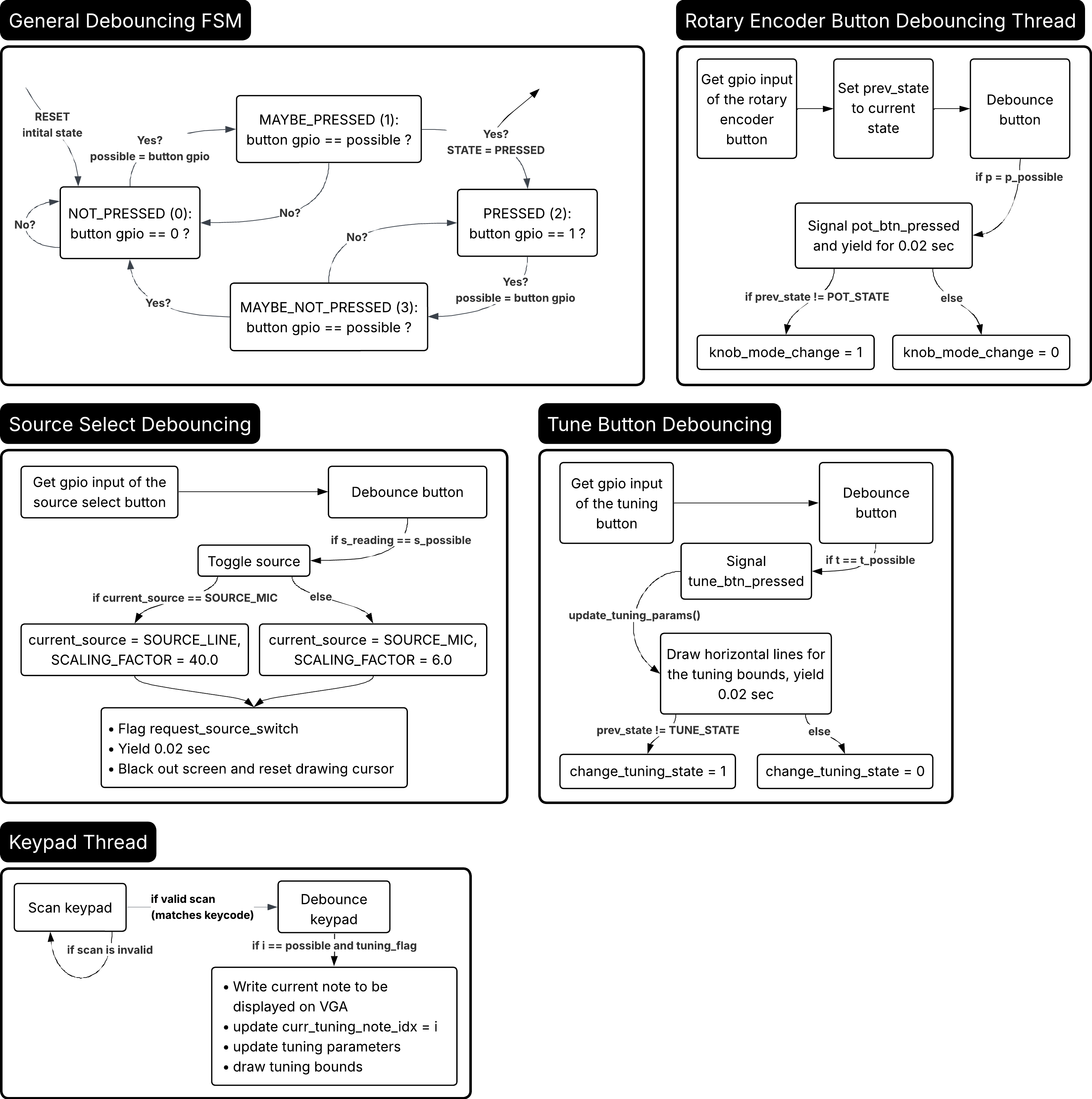
In this project, because we used buttons, a keypad, and a rotary encoder, debouncing was necessary to obtain a proper representation of the current state. The general debouncing algorithm for the buttons (including the button for the rotary encoder) consists of checking the current value of the GPIO correlating to the button input against the previous value to ensure that the value actually was pressed low (see the debouncing FSM). Once the FSM transitions from the MAYBE_PRESSED state to the PRESSED state, an action is performed. After the action is performed and the FSM is transitioning out of the PRESSED state, the thread yields for 200 ms because the buttons we used tend to register multiple presses, toggling back and forth between modes unintentionally. By implementing this brief wait, any presses closer together than 200 ms are disregarded.
For the debouncing of the tune button, the action performed is the signal of the tune_btn_pressed semaphore. It also updates the tuning parameters with update_tuning_params() and draws the initial horizontal tuning bounds. If the tuner was previously not in the tuning state, it changes the chane_tuning_state flag to 1 and 0 otherwise. For the debouncing of the source select button, the action performed is to toggle the source between the mic and the line-in. It flags the semaphore request_source_switch and then resets the spectrograph graph. Finally, for the rotary encoder button, the semaphore pot_btn_pressed is signaled and the knob_mode_change flag is changed to 1 if the state of the encoder button is no longer equal to the previous state (if the button was pressed).
As for the debouncing of the keypad, we used the same algorithm that we did in lab 1. We scan the keypad incrementally by setting the GPIO's attached to the columns of the matrix high one at a time and then reading the states of the 7 GPIO's attached to the keypad. The result is then shifted to the right by 9 and then masked with 0x7f, resulting in a 7-bit number where every bit represents a pin of the keypad. This value is then compared to an array of scancodes which correlate to the numbers on the keypad. If the press doesn't match any of the valid keycodes or no button is found, i = -1 is reported. In addition to deciding which key is pressed, there is an additional debouncing algorithm which is the exact same as the state machine used for the other buttons in this project. The action performed in the transition from the MAYBE_PRESSED to the PRESSED state only occurs in the tuning state (tuning_flag = 1). If tuning is enabled, the current note that is mapped to the keypad index resulting from the scan is saved to a buffer to be displayed. This index is retained for use elsewhere in the program, and the parameters are updated with update_tuning_params() to ensure accurate tuning to the new note. The screen is then cleared and tuning bounds are redrawn.
Since we had experience with using the ADC input from potentiometers from the other labs to tune different parameters in the programs, we planned to do the same with our tuner to make the tuning experience customizable. Unfortunately, the FFT code depends on ADC input from the audio input, which would require us to synchronize the ADC source switching. While attempting to switch sources between the audio input and the potentiometer input, we ran into many problems. Moreover, low-passing/averaging the input signal proved finicky and the spectrogram stopped working because of the handling of the source switching. After many hours trying to debug the potentiometer ADC integration, we decided to consult Professor Adams, who proposed using a rotary encoder. This would allow us to keep the ADC source switching exclusively to the audio input and vary the parameters with a digital input.
After pivoting to the rotary encoder from the potentiometer, we needed to find a way to debounce the rotary encoder since the mechanical contacts inside of the rotary encoder bounce while switching just like a push button. Instead of implementing this, we found an open source library online called “librotaryencoder” by Marcus Holland-Moritz that gave us the necessary .h files. The C/C++ library is easy to use and supports many types of encoders, which was optimal for our purposes. Professor Adams had given us a rotary encoder that worked best with the half-step debouncing function (each mechanical bump correlated to one increment/decrement). Later on, we ended up finding a threaded rotary encoder which would make assembling the final product easier. Unfortunately, we had to pivot to using the full-step debouncing function after testing the different encoder, which was made significantly easier through this library (only had to change the function called to the full-step version). Full-step encoders have detents every full step (waits until 11 is encoded to trigger), while half-step encoders have detents every half step (11 or 00 encoded). The rotary encoder was quite nice because when spun, there is a tactile feel to the mechanical contacts going over the common pin bump.
The rotary encoder code worked by reading the terminals of the encoder (there are two), which toggle their respective GPIO pin voltages each time the knob is rotated. They toggle in a different order depending on the direction that the knob is rotating, which allows the microcontroller to ascertain the direction of rotation each time a movement of the encoder is detected. Our code reads the encoder's terminals, writing the result to a bitmask and then passing it into the encoder library, which uses a state machine implemented using bitwise logic operators for performance to quickly discover the direction of rotation. This output is then routed through update logic that allows the program to alter the value of a parameter, if one is currently selected for modification. The parameter selected for modification and its current value is displayed on the screen until the user clicks the button attached to the encoder knob to get to the “Standby” mode, where no parameters are modified, regardless of rotation.
d. State Machines

As mentioned before, pressing the buttons often resulted in the signalling of a semaphore (tune_btn_pressed, pot_btn_pressed). These semaphores result in the triggering of FSMs that wait on them. Since the states automatically cycle with a button press, the state is determined by T_CYCLE_STATE = (T_CYCLE_STATE + 1) % 2. This allows the cycle to initialize in TUNE_DIS (0), go to TUNE_EN (1), and then back around with a button press. Upon each toggle of the tuning enabled/disabled state, the spectrogram is reset (screen is blacked out and the cursor is reset to the initial x) and when tuning is enabled the tuning_flag is set to 1.
The rotary encoder FSM waits on pot_btn_pressed to be signalled by a valid button press. We initially had a state machine similar to the tune button FSM, but then decided that the rotary encoder should only enter the MOD_OCTAVE state to modify the tuning octave when tuning is enabled. This changed the logic slightly, where before, the button would cycle through every state dictated by STATE = (STATE + 1) % number of states. Now, the incrementing of the states is handled through a series of if statements. The current state will only progress from MOD_SCALING_FACTOR to MOD_OCTAVE if the tuner state is enabled. Otherwise, the state will reset to the initial state and restart the cycle. While tuning is enabled, the states of the rotary encoder progress through MOD_OCTAVE, which transitions back to the initial state to reset the cycle. In the states themselves, the variable being adjusted is copied to a buffer which is displayed on the VGA display and the current state (pot_funct) is retained.
We implemented a separate protothread which updates the parameter corresponding to the current state of the encoder (pot_funct) based on the motion of the rotary encoder. First, we read the encoder terminals with read_encoder_terminals() which samples the GPIO pins connected to pins A and B of the encoder. Then, we pass the current encoder state and the reading to encoder_debounced_full_step_update(), a function from the librotaryencoder library. The return value is saved as a static enum encoder_action result, which indicates if the rotary encoder was rotated clockwise or counterclockwise.
We interpret a clockwise rotation (ENCODER_ACTION_TURN_CW) as adding one step to the currently selected parameter, and a counterclockwise rotation (ENCODER_ACTION_TURN_CCW) as subtracting one step. The current editable parameter is determined by the states of the rotary encoder (pot_funct). For a CW action, if the current parameter (MOD_SCROLL_SPEED, MOD_CENTER_FREQ, MOD_SCALING_FACTOR, or MOD_OCTAVE) is less than the maximum value, then one increment is added for every edge detected. If the current value is equal to the maximum value we defined in the program, then it is clamped to that value and no longer increases. The opposite happens with CCW actions. If the parameter is greater than the minimum value, then one decrement occurs for every edge detected. If the current value is equal to the minimum value, then the parameter is clamped to that value and no longer decreases. Now, if any of the parameters are no longer equal to the previous value, then the knob_value_change flag is set high so the VGA thread knows when to update the display.
e. "Noncritical" VGA Display
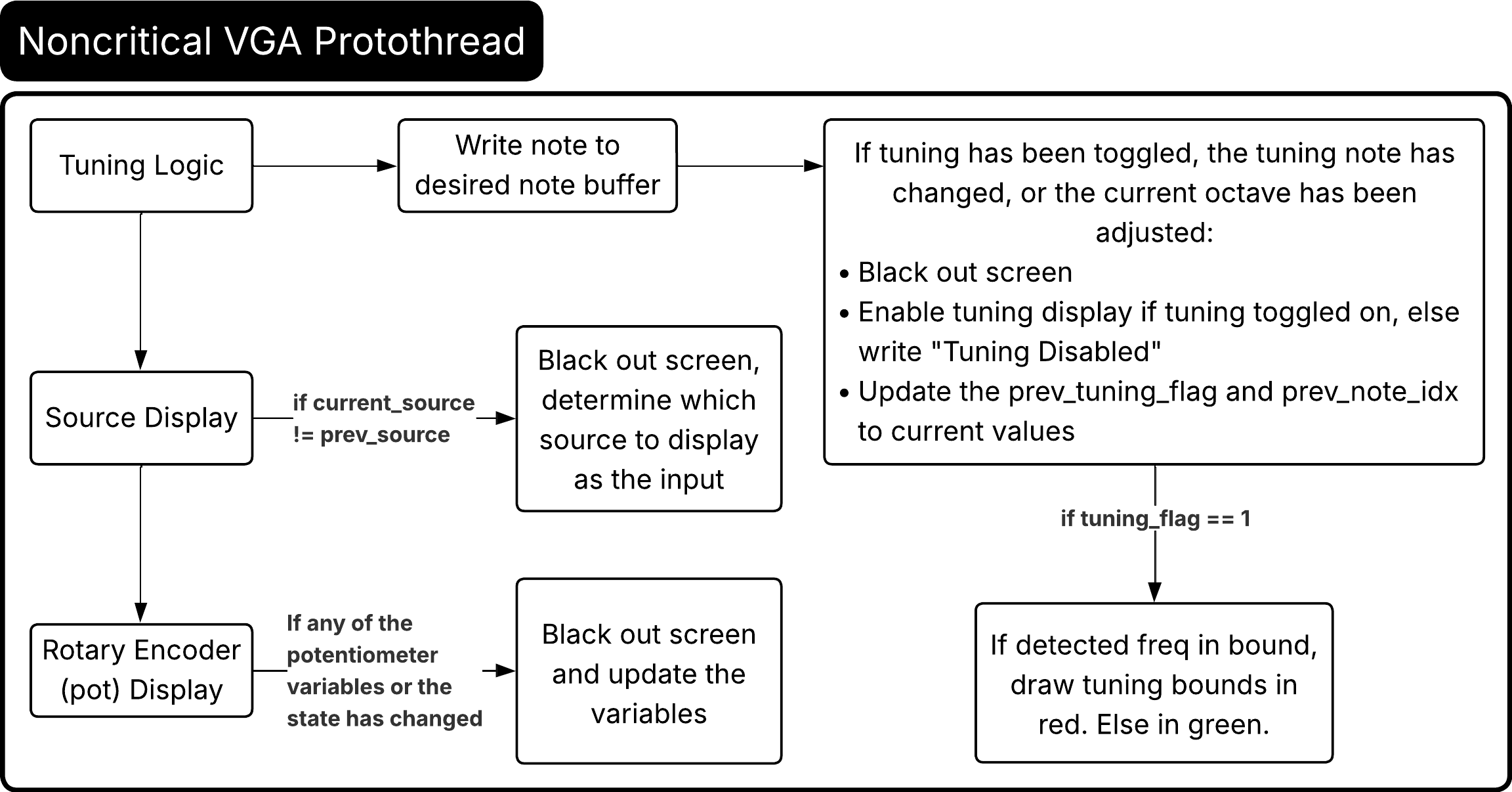
The final protothread, protothread_noncrit_vga handles the VGA display tasks other than the spectrogram which allows us to distribute the display load across the two cores. Upon program initialization, the display defaults to showing that the input source is the mic and the current state of the rotary encoder and tuning state of the tuner. While the program is running, we divided the logic into three blocks: the tuning display, the source display, and the rotary encoder display. Essentially, this breaks the thread into logical blocks that correspond to the primary customizable elements of the tuner.
In the tuning block, the current note is first copied to a buffer. Then if any of the states have been changed (tuning toggled, current note changed, octave changed), then the spectrogram is blacked out and the cursor is reset. If tuning was enabled, then the note being tuned to and the current octave (ie: Tuning to: C4) is displayed on the screen. Otherwise, the VGA screen displays “Tuning Disabled”. In both cases, the current tuning status and current note are saved for comparison. Now to actually show if the note being played is tuned within +/-40 cents of the desired value, we use the calculated values of the ubound_freq and lbound_freq. While tuning is enabled, if the detected frequency is less than or equal to the upper bound and greater than or equal to the lower bound of frequency, then the drawn horizontal bounding lines are drawn in green, signalling that the frequency played falls within the bounds. If the detected frequency falls outside of the bounds, then the horizontal lines are drawn in red.
The VGA display will only update the display pertaining to the source if the audio input is toggled. It will then write the proper string to the screen, either “Input: Mic” or “Input: Line-in”. It will also update the scaling factor based on the input chosen. For the microphone, we found that it was more sensitive, so we only needed to set the magnitude scaling factor to 6. As for the line-in, we found that it required a higher scaling factor to show up properly on the display, so we set it as a baseline to 40. Having it automatically update when the sources are switched makes the tuning experience more streamlined.
Finally, the rotary encoder display is only updated when either the rotary encoder state is changed, or if any of the parameters is changed (SCROLL_SPEED, CENTER_FREQ, SCALING_FACTOR, OCTAVE). The spectrogram is blacked out and the cursor is reset and the current state of the rotary encoder is written to the string. The previous states of all of the parameters are now updated with the current state.
f. Main

In main, we initialized all of the GPIOs (majority pulled up if they were buttons), overclocked the Pico, configured the ADC and DMA, initialized the encoder state, initialized the semaphores, and then launched both cores. We ended up using core 0 exclusively for the FFT protothread because we didn't want anything else to run on core 0 and possibly interrupt the FFT thread. This ensures that the spectrogram will run smoothly. On core 1, we had all of the other protothreads including the debouncing, FSMs, and noncritical VGA display tasks.
Hardware Details

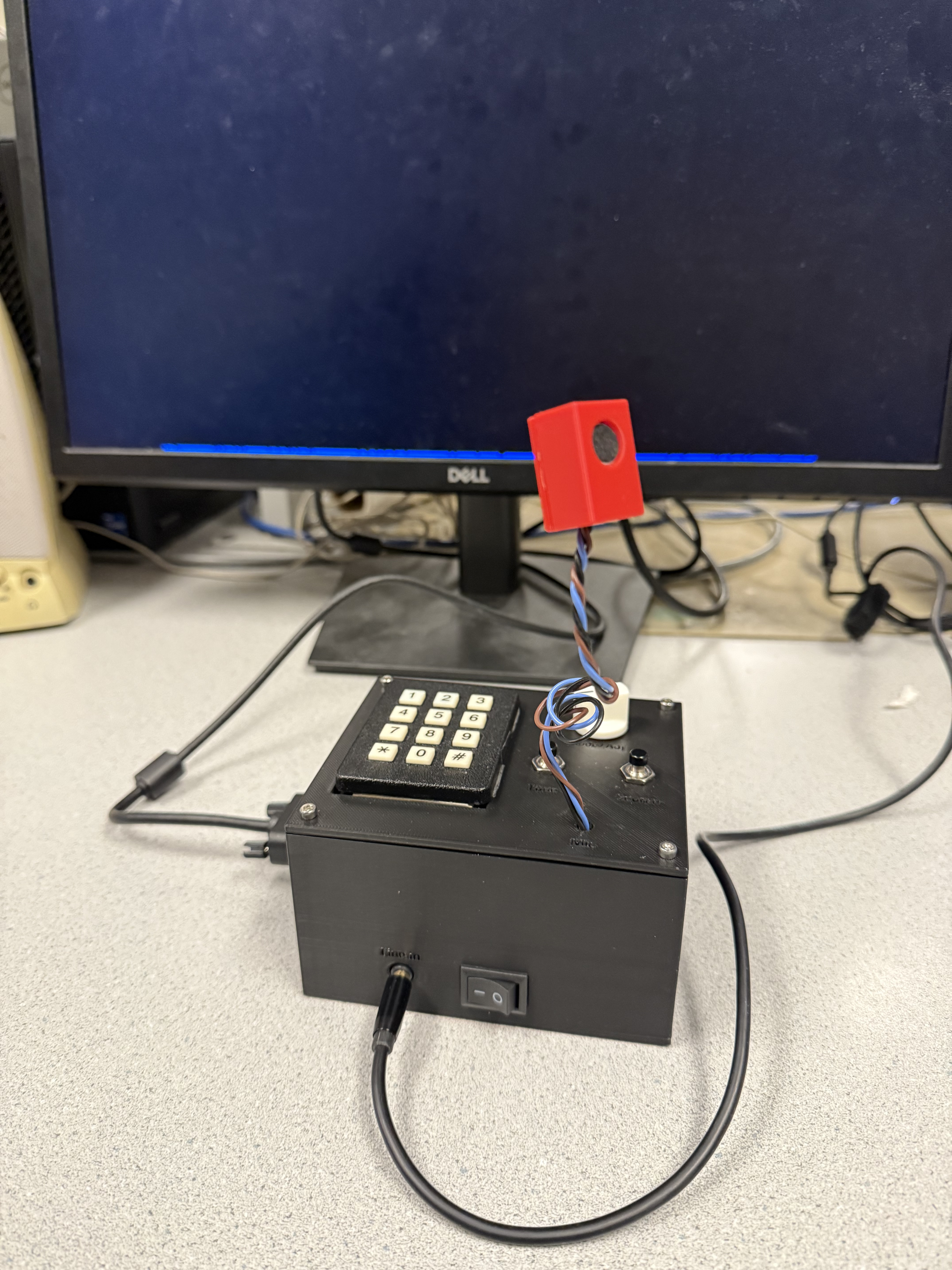
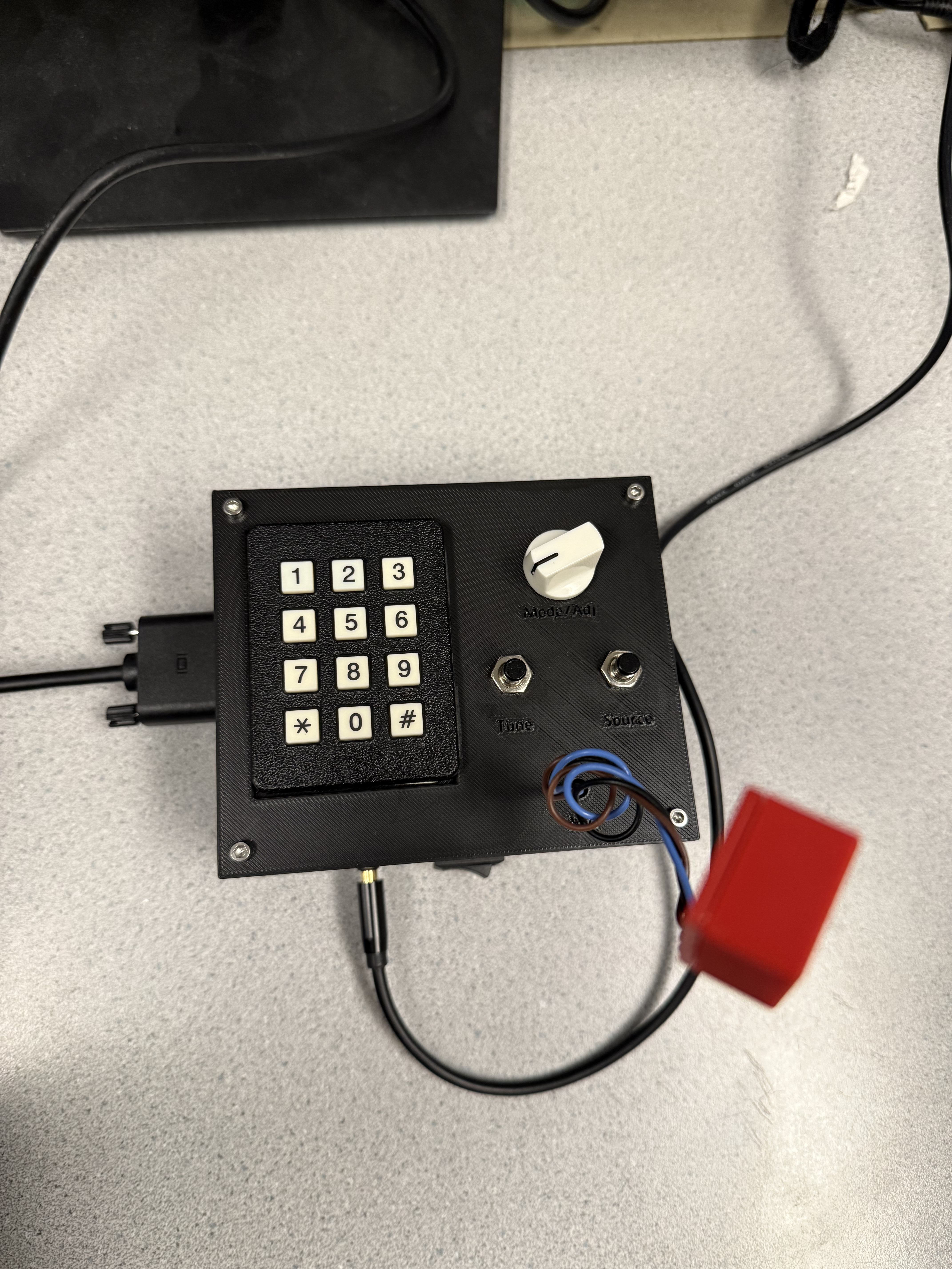
At a high-level, we used a Raspberry Pi Pico (RP2040) microcontroller overclocked to 250 MHz. Other various crucial components that will be described in detail later include, two buttons, a rotary encoder, a mic, a line-in, a keypad, and a VGA breakout board. We used solderable proto-boards and wires to make the connections, so nothing would come apart. All together, the hardware was enclosed in a 3D printed enclosure and powered off of AA batteries (power can be switched on/off with an external switch), which further contributed to making the final product feel like something you could purchase. We also made sure that there was a diode connected in series between the switch/battery and the VSYS pin to prevent back emf.
The hardware connections to the Pico are described in the Pico Hardware Connections Map (change name if necessary). All of the grounds are connected to the various grounds of the Pico wherever convenient. We included a soldered Bootsel button for debugging, but in a final product, one may omit this since it was purely for development purposes.
The main user interface consisted of two tactile switch buttons, a rotary encoder, and a keypad. Regarding the tactile switch buttons, there is one for the input selection between the mic and the line-in, and one for toggling between the tuning enabled and tuning disabled states. The rotary encoder was used for both incrementing/decrementing tuning and display parameters as well as a button to cycle between the various adjustable parameters. The keypad was used to select the base note in the fourth octave to tune to (ie: A, A#/Bb, etc.). All together, these parts formed the critical user interface of our project, allowing the user to interact with and customize their experience with the tuner.
The rotary encoder is a digital hardware component that has three data wires, one for the momentary button switch integrated under the knob, and two for the encoder terminals. The encoder also required the connection of a 5V power supply, so it was connected directly to the VSYS pin that outputs 5V under USB and battery voltage when the Pi Pico is powered by an external battery. Our three AA battery pack was close enough to the 5V requirement to ensure accurate function of the rotary encoder. As a hardware device, the rotary encoder contains two switches, each of which are toggled on and off when the knob is rotated one click in either direction. The two terminal pins for the encoder were connected to GPIO pins on the Pi Pico. These pins toggle with the switches inside of the encoder, and the order of toggling is used by our program to ascertain the direction of rotation, and thus whether we should increase or decrease the value to be modified.
The 3x4 keypad is a grid of wires and switches (see Figure 6) with 7 pinouts. Four of the pins are connected to each row of the keypad (which we connected to 330Ω resistors on the output to prevent the circuits from being shorted when multiple buttons are pressed at the same time), and the remaining three are connected to the columns of the keypad (which have internal pull down resistors). Internally, there are 12 switches and each switch is connected to one row wire and one column wire, shorting when the specific key is pressed. For instance, pressing the 1 key shorts the pin attached to row 1 to the pin attached to column 1. We connected the 7 pins of the keypad (with pins 1-4 in series with 330Ω resistors) to GPIO pins 9, 10, 11, 12, 13, 14, and 15 respectively.
As for other hardware that was critical for the functionality, but not necessarily user-variable, there was a microphone for basic audio input, a line-in to connect an audio jack for input, and a VGA breakout PCB. We wanted to make sure that the user could interact with the tuner in various ways, so we included two different options to input audio. The user could either provide input through the microphone, or if the user had an amplifier or wanted input from a computer for example, they could use the line-in. The mic was tuned to make sure that the gain was sufficient enough to steer clear of most noise while keeping the spectrogram graphic representative of the audio. It is powered by the 3V3 pin of the Pico since the input VCC requires 2.4-5.5V. The left and right pins of the audio jack are bridged to make it mono audio. The VGA breakout board is the same one used in the previous labs, consolidating the traces and resistors required, and allowing a direct interface from the tuner to plug the VGA cable into any VGA display.
Attribution
We used some outside code and libraries over the course of this project. Those that were not provided as part of the course are linked at the bottom of this report. We used the VGA driver and RP2040 protothreads library, as well as the fix15 implementation of the Cooley-Tukey FFT provided in the RP2040 Demos. Outside of Professor-provided code, we used a library for the rotary encoder logic. We could have written our own, but a pivot from potentiometer to rotary encoder when our ordered hardware never arrived led us to switch to the encoder relatively late into our project and we had bigger fish to fry. The encoder library is free and open source, and is even freely licensable for commercial use!
AI Use
AI was used in the formatting of the tables in appendices A and B. AI was also used to troubleshoot small semantic errors, but did not become particularly useful, since it didn't have context of protothreads or the hardware layout of our design. We didn't run into much debugging that was too complicated to solve by sitting down and combing through code or inspecting hardware.
4. Results of the Design
Test Data and Visuals
To test the tuner, we decided to use drones from an existing tuner to see how accurate we were. We first went through the notes in the fourth octave, using a center frequency of 440Hz (initial state). Correct tuning was indicated when the spectrogram displayed magnitudes within the tuning boundaries and the boundary lines turned green. Then, we went through the octaves for various notes to verify that throughout the octaves, the tuner would still register the correct pitch throughout the range. Then, we changed the center frequency (ie: to a value of 470Hz) for both the spectrotuner and the testing tuner. From there, we saw that the tuning display was still accurate. This behavior is demonstrated in the demo video above.
Speed of Execution
A large part of our effort to improve user experience while using our device involved reducing any kind of display artefacting while also providing the smoothest, fastest rendering for the spectrum and tuning indicator bars. We achieved this by overclocking the RP2040 to 250 MHz, reserving Core 0 for the FFT, and implementing measures to smartly handle user input. Two things we did include only redrawing textual information about mode of usage to the VGA when parameters were changed, and adding short yield times to our debouncing threads. These resulted in much more user-friendly input flows, since the buttons became less finnicky and more responsive to gentle presses, and the text on the screen did not appear to strobe or flicker at all. Because of our parallelization method, we did not experience any slowdowns or bottlenecking that would commonly be associated with halting a heavier process to handle small user inputs. Overall, while there are probably places to speed up our code, our implementation worked well without any user-apparent resource issues.
Accuracy
The tuner is quite accurate. When tested with drones, the tuner lit up when expected and passed the various tests of changing the center frequency, notes, and octaves. The cents range is adjustable, and we chose to have a wider tuning margin (+/-40 cents) to cater to the average person's vocal range. In a future iteration, we could implement another user input mode to change the tuning tolerance. This would not be computationally intensive since we precalculate the tuning tables and they would all need to be recalculated only once per modification, with no impact on live tuning performance.
Safety
Our design is safe, there are no aspects where a user can get injured. There is input current protection with the diode, and the power source itself of 3 AA batteries is a low votlage power source.
Usability
The enclosure itself is quite sleek, and the buttons are all labeled with the appropriate function, so spectrotuner is arguably generally user friendly. The only annoying parts are the requirement to use a VGA display, and the need to use an audio splitter if using the line-in and wanting to also send the signal to a speaker or amplifier for listening.
5. Conclusions
Analysis
Our results were thankfully well-aligned with our expectations and the specifications laid out in our project proposal. It functions well as a spectrogram and tuner, making it creatively and musically useful, which is what we set out to do. However, the requirements of using a vga display for video output and a 3.5mm audio splitter to allow the signal to be analyzed and played through speakers simultaneously are somewhat annoying. If we were to iterate on our project, the first hardware changes we would seek to make would be adding an audio passthrough to remove the requirement of using a splitter, as well as integrating a VGA to HDMI converter or similar type of technology. This would probably be done with external hardware since writing an HDMI driver for the Pico would most likely be a questionably-valuable task. Additionally, since our spectrogram only renders up to five kilohertz as a result of the Pico's onboard ADC. To cover the full human-audible range of frequencies, we would need to quadruple our sampling rate from 10 kS/s to 40 kS/s. This could either be done by adding a more capable/less noisy external ADC, or by simply increasing the sample rate of the Pico's onboard ADC and changing the parameters of the spectrogram to allow the display of frequencies higher than 5 kHz. If we made this change, we would probably also add a user option to adjust the scaling of our video output to be logarithmic instead of linear, so that the display would be capable of showing either the real or perceived distance between the frequencies picked up by the device.
Standards
Since our design does not occupy any strictly regulated space, we did not have to consider many standards. We were able to use the VGA standard for video output successfully. This was in part due to the ease of use of the RP2040 VGA Driver provided earlier in the course, and also the work we did in overclocking the PIO state machines and RP2040 to support a higher refresh rate. We reused some code, to include the protothreads library, VGA driver, encoder library, and FFT code. All oustide-ECE 4760 code that we found and used during the course of this project was free and licensed for both commercial and non commercial use. We did not reverse-engineer any part of our design, and we did not infringe on any trademarks or patents. We did not have to sign an NDA to get any sample parts. There may be patent opportunities for this project, since all code we used is redistributable/licensed for commercial and noncommercial use. Our project is relatively unique, and there are not currently any patents for it, so we could possibly apply for a patent. Obviously, we would need to check with a patent attorney to see if it is actually viable for a patent, but since it is a concrete, specifically useful thing that hadn't existed (to our knowledge) before we designed and built it.
Intellectual Property Considerations
We did resuse some code in our project, including the protothreads libary, rotary encoder library, FFT code, and VGA driver. All of this code was either provided over the course of this class, or is licensed freely for private and commercial use. We did not reverse engineer any designs, so we do not need to worry about the consequences of that type of situation on this project. We did not use any patented or trademarked code to build our device. We did not have to sign any NDA to get parts since all of our parts were directly from the lab or 3D printed at Cornell from designs that we created. As mentioned above, it is potentially possible for us to get a patent for our device (at least as far as we can tell by the requirements to patent a technology/device on the internet), however we would probably need to do some more design work to make it production-viable.
6. Appendix A: Permissions
Project on the Course Page
"The group approves this report for inclusion on the course website."
Project on the Course YouTube Channel
"The group approves the video for inclusion on the course youtube channel."
7. Additional Appendices
A. Pico Hardware Connections Map
| Purpose | GPIO | Pin Number |
|---|---|---|
| VGA | ||
| VGA Hsync | 16 | 21 |
| VGA Vsync | 17 | 22 |
| VGA Green | 18 | 24 |
| VGA Green | 19 | 25 |
| VGA Blue | 20 | 26 |
| VGA Red | 21 | 27 |
| Keypad | ||
| Pin 1 → 330 Ω (row 1) | 9 | 12 |
| Pin 2 → 330 Ω (row 2) | 10 | 14 |
| Pin 3 → 330 Ω (row 3) | 11 | 15 |
| Pin 4 → 330 Ω (row 4) | 12 | 16 |
| Pin 5 (col 1) | 13 | 17 |
| Pin 6 (col 2) | 14 | 19 |
| Pin 7 (col 3) | 15 | 20 |
| Rotary Encoder | ||
| Encoder Pin A (CLK) | 2 | 2 |
| Encoder Pin B (DT) | 3 | 3 |
| Encoder Button (SW) | 5 | 7 |
| Encoder Power | VSYS | 39 |
| Buttons | ||
| Tuning Enable Button | 22 | 29 |
| Input Select Button | 4 | 6 |
| ADC | ||
| Microphone Input | 26 | 31 |
| Line-in Input | 28 | 34 |
| Power | ||
| Battery Pack → Switch → Diode | VSYS | 39 |
| Microphone Power | 3V3(OUT) | 36 |
B. Bill of Materials
| Part | Part Purpose | Part Price | Qty | Part Link / Source |
|---|---|---|---|---|
| RP2040 | Microcontroller | $4.00 | 1 | Adafruit |
| Push-Button Rotary Encoder | Choosing tuning reference frequency and mode of operation | $1.89 | 1 | DigiKey |
| Knob | Improve device ergonomics | $1.53 | 1 | DigiKey |
| Buttons | For toggling tuning and between sources | $2.00 | 2 | Manic Music |
| Keypad | Choosing tuning pitch (the desired note) | $6.50 | 1 | Adafruit |
| Line-in jack | For connecting from an amp or pedal | $0.64 | 1 | DigiKey |
| Electret Microphone | For picking up sound to be tuned | $7.95 | 1 | Adafruit |
| VGA Board | Device display output | N/A | 1 | Proprietary (lab stock) |
| Rocker Switch | For turning on the device power from the batteries | $0.71 | 1 | DigiKey |
| Diode | For preventing back emf to the batteries | $0.13 | 1 | DigiKey |
| AA Batteries (3 pack) | For powering the device | $2.25 | 1 | Adafruit |
| ¼” to 3.5mm Adapter | For allowing audio cable to connect to device | $5.99 | 1 | Amazon |
| PLA Filament | Print Device Enclosure | N/A | N/A | Lab stock |
Appendix C. Team Contributions
| Team Member | Tasks |
|---|---|
| Jack Chaney |
|
| Arielle Huang |
|
D. Source Code
Code files used in the project can be found on the final-project branch in this repository: https://github.com/jbc-BigRed/RP2040-demos/tree/final-project/Audio/f_Audio_FFT
8. References
- Data Sheets:
- Raspberry Pi Pico W Datasheet
- RP2040 Datasheet
- Rotary Encoder Datasheet
- Microphone Amplifier Datasheet
- Vendor Sites: Digikey, Adafruit
- Code/Designs Borrowed: ECE4760 course library, RP2040 fft.c demo code (V. Hunter Adams), “librotaryencoder”
- Background Sites/Papers: Understanding the Cooley-Tukey FFT, Keypad interfacing, Protothreads