Demo
To see a demo of our robot working please visit this link: https://youtu.be/Jd0DRI0JFwQ
Introduction
We created a two-wheeled self-balancing robot that uses PID control to balance while moving forward and backwards.
Summary
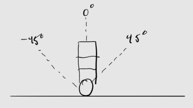
What we did: We spent somewhere between 4 and 5 weeks on designing, building, and tuning our final project. The main specification of this project was to create a two-wheeled self-balancing robot that could balance in place with slight disturbances, like slightly pushing the robot one direction or the other, and move forwards and backwards. We had extra reach goals of being able to turn in place and climb up sloped surfaces, but we did not have enough time to do these extra features. To have the robot balance itself, we approximate the current angle of the robot by means of a complementary filter that takes gyro and accelerometer readings from an IMU seated at the top of the robot as inputs. This angle is then used in a PID controller to send PWM waves with different duty cycles depending on the PID controller output to make the robot balance. Four PWM signals are passed through two H bridges so that we could control the two motors independently at any speed and in both directions. We used hardware techniques such as isolating the noise from the motor controller with an optoisolator. We will also discuss this in the hardware section of the report. For users to interface with the robot, they can use wired UART communication via the serial monitor of a computer. The serial monitor will prompt you to make commands that can adjust the PID gain values as well as tell the robot to go forwards, backwards, or balance in place. The robot's balancing position is at 0 degrees, as seen in Figure 1.
Why we did it: We really enjoyed lab 3, where we used PID control to set a target angle for a 1D helicopter. We used this project as a means to explore our interests in control engineering, physics, and robotics. We learned the challenges of building a physical robot from scratch and how you need a background in mechanical, electrical, and software engineering to create a robot limited by the physics of our environment. We developed a great deal of respect for mechanical engineers through our struggles with the development of the chassis of our robot. Additionally, self-balancing robots are used in a variety of applications, such as an aid for those with disabilities, with research being done to make self-balancing wheelchairs.
High Level Design
Rationale and sources of our project idea
The source of this project idea came from our love for Lab 3 and control systems. We thought it would be both an exciting and challenging project that had a good mix of mechanical, electrical, and software design. The extra challenge is that there are two motors, and they can go in either direction. We are also on our own for designing the mechanical design and not provided a mechanical design like we were in lab 3. This project really challenged us, and we are proud of our work.
Logical Structure

Background Math
Inverted pendulum physics
Our self-balancing robot is practically an inverted pendulum. To keep the math simple, we will assume the main chassis of the robot is like a rod with no moment since the weight at the top of the robot from all the batteries is much heavier than that of the chassis, so we can make this assumption. Given the diagram below, we can find the torque.
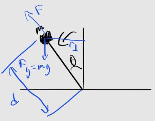
\begin{align} \tau = mgd \sin{(\theta)} \end{align}
By neglecting the moment of the rod:
\begin{align} I = md^2 \end{align}
Torque is also defined as:
\begin{align} \tau=I\ddot{\theta} \end{align}
Setting both torque definitions equal to each other and simplfying and we get:
\begin{align} mgd\sin{(\theta)}=md^2\ddot{\theta} \end{align}
\begin{align} \ddot{\theta}=\frac{g}{d}\sin{(\theta)} \end{align}
This result shows us that with a greater d (the majority of the mass is higher up the robot), then we will have less angular acceleration. This is a benefit for our robot because then this means our robot will fall over slower, and the robot will have more time to self-right itself. The drawback is that increasing d will also increase your torque, so we will need motors with more torque the higher we put the majority of the mass. It is also important to note that the angular acceleration is dependent on the angle you are at, so it is a non-constant angular acceleration. However, we just use some simplifications and approximations just as a way to understand our system. This math was provided to us from this youtube lecture.
As an aside, there are no patents, copyrights, and/or trademarks which are releveant to our project.
Program and Hardware Design
Hardware Design
Overview
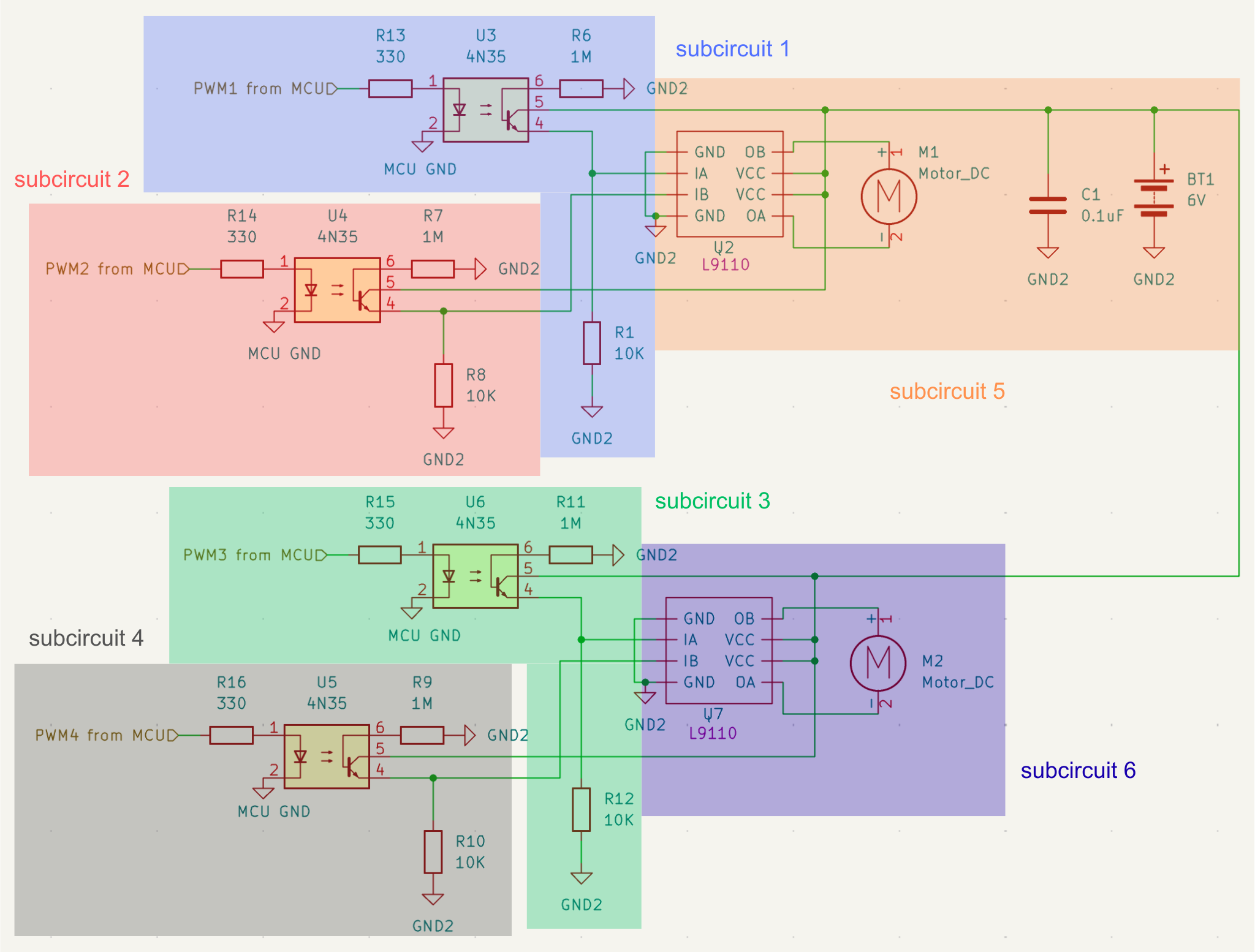
This final project consists of thirteen types of components: an RP2040 microcontroller, two full-sized perma-proto breadboard PCBs from Adafruit, two hobbyist DC motors, two wheels, rubber bands, seven rechargeable AA batteries, two battery holders, four optoisolators, two H-bridge ICs, an MPU-6050 six-DoF gyroscope and accelerometer, two screw terminals, four wooden dowels, and many Legos. :) We have two main circuit designs for this final project, which we will discuss more in the circuit design section. Optoisolators are used in the motor control circuit to electrically isolate the electrical noise generated by the motors. See appendix E for the bill of materials (BOM).
Structural Design
Let’s first discuss the mechanical design of the robot. The chassis of the robot is made out of Legos and consists of three main layers. The bottom layer is a rectangular Lego base to which we attached two DC hobbyist motors (more on this later) with two M3 screws per motor and nuts to secure them in place. We added two wheels to each motor and wrapped rubber bands around them to increase friction with the surface the robot was on. The second layer was also a rectangular Lego base where we duct-taped our motor control circuit board, whose design we will discuss more about later. This layer also held the three AA rechargeable batteries that powered the MCU. The third and final layer was also made out of Legos, and we duct-taped the MCU and IMU protoboard to this layer, which we will discuss more later as well. This layer held the four AA rechargeable batteries for the motor control circuit, and the reason this was on the top layer was because we wanted most of the mass to be on the very top of the robot for reasons explained in the background math section above. All three layers were separated from each other, as seen in figure 2, by air/gaps and connected with four wooden dowels at the corners of each base. The top layer was hot-glued in place so it wouldn’t slide along the dowels since we wanted to keep as many variables of the system constant as we could. We will discuss more of the iterations of the mechanical design in the previous iterations section of the report. Some of the Legos were also not toleranced well, so we had to use rubber bands to hold them together. This three-layered design was inspired by other self-balancing robots that we saw online, like this one.
Circuit Design
Now, we shall delve into the circuit design of the two protoboards. The first protoboard we soldered was a motor control circuit with the schematic shown in schematic 1. This motor control circuit was inspired by the one provided to us on the course website.
Motor control circuit design
Our motor control circuit takes in four square PWM waves oscillating on and off, generating fields that create electrical noise, which could interfere with our IMU. Strong electrical noise could cause the measurements of the IMU to be too noisy, and the IMU provides the data for the complementary filter, which acts as one of the inputs for our PID controller. Garbage data means garbage PID controller output, which would make it difficult to control an already hard control problem. Also, the electrical noise can cause our IMU to hang, and if the IMU hangs, the whole system will hang. This problem is amplified compared to lab 3 of this class, where we designed a 1D helicopter arm, because now we have 4 PWM signals instead of just one. The wires of the PWM signals are also longer now because of the height of the robot.
In addition to the noise from the PWM signal from the MCU, the two hobbyist motors create a lot of noise as well since they are brushed DC motors. We must be mindful of where we place the motors so that the noise generated from these motors and the motor control circuit does not interfere with the IMU. This is why we have a separate platform for the motor control circuit as well as a separate platform for the motors so that both are far enough away from the IMU. One of the many challenges of building a physical robot is that even with perfect software, the physics of the system impacts the functionality and design of the robot. It is necessary that we electrically isolate the two DC motors from the MCU and the IMU.
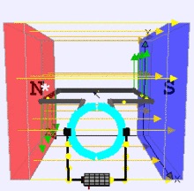
First, let’s think more deeply about how these DC motors generate so much noise to motivate the design choices we made to isolate the noise. Both of the hobbyist motors are brushed DC motors with a built-in gearbox. The way DC motors work is that they use permanent magnets to generate a magnetic field. The armature (coil of wire) is put inside the magnetic field seen in figure 4 below, in between the two magnets. A Lorenz force is generated, causing the armature to rotate, and there is a commutator whose job is to flip-flop the direction the current flows through said armature so that the motor rotates in the same direction. Back-EMF creates a big source of noise, and this back-EMF gets worse as the armature rotates faster and faster. If we load the motor, it will rotate slower. If we unload the motor, it will rotate faster, decreasing the torque and increasing the back emf. Since both motors are attached to wheels at the bottom of the robot, both motors are under constant load, which decreases the back EMF, so the effects aren’t as bad as if they were allowed to spin freely.
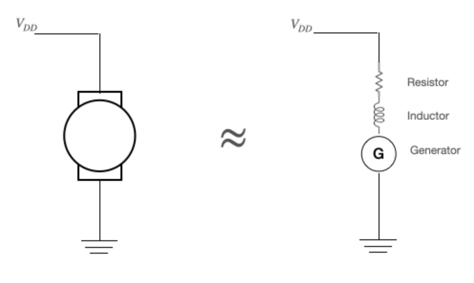
We learned in the lecture that the motor can be approximated as a generator, inductor, and resistor all in series, as seen in figure 5. For an inductor, $V=L\frac{dI}{dt}$ by definition, so because of the rapidly changing PWM signal, the dI/dt term will explode, which causes the V term to explode, so we need a safe way for current to go to ground. We do not need to add a snubber diode like in lab 3 since the L9110H H-bridge driver IC we attach the motor to has a built-in kickback diode as specified by the datasheet. Additional high-frequency noise from the brushes of the motor will be attenuated by means of a bypass capacitor as seen in schematic 1 with the capacitor C1 with capacitance 0.1 uF. The high-frequency noise is bypassed along the safe path of the capacitor. We chose a ceramic capacitor because electtolytics are too slow for our application.
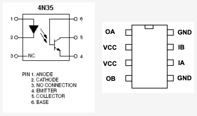
Here comes the really cool part. Another way to avoid the noise generated by the DC motors was by using four opto-isolators (the 4N35). By using an opto-isolator, the MCU and motor control circuit will have separate grounds and power to completely isolate the motor noise. We do not want current to flow from the MCU to the motor or vice versa. The opto-isolator seen in figure 6 is an LED and a phototransistor in one IC package. So we transfer information not with an electrical connection, but through the light of the LED. The 330-ohm resistor in schematic 1 is just a standard current-limiting resistor so the LED does not blow. The 1M ohm resistor is used to control the speed the photocurrent leaks off the base of the optoisolator IC to the 6V batteries’ ground. We do not want current leaking off too fast with a low resistor value since this prevents us from turning on the BJT/phototransistor. On the other hand, we don’t want it to leak off too slowly because then it would take too long to turn the transistor on again. The 1M ohm resistor allows the transistor to turn on and off at a frequency of 1 kHz, which is good because that is the frequency our PWM runs at and the frequency of our control loop. The 4N35’s bandwidth is what limits the frequency of the PWM. The 10kohm resistor in schematic 1 just ensures we do not short power to ground when the BJT/phototransistor is turned on. Note that it is on the bottom part of the BJT because it acts as a low-side switch, so we don’t have to invert the PWM signal. If we want an inverted signal (discussed more in the software section), we can always change this with the software. For consistency, we shall keep subcircuits 1, 2, 3, and 4 all as low-side switches.
The L9110 H-bridge seen in figure 6 contains one full H-bridge, or in other words, two half H-bridges. This allows us to operate one DC motor in either direction with a current output limit of 800 mA and for voltages between 2.5 and 12 V. The hobbyist DC motors have a max load current of 200 mA and operate around 4.5V. The IC also has a PWM input for each driver, which is why we send two PWM signals from the MCU to one of these H-bridge ICs, as seen in schematic 1. Of course, one signal always has a duty cycle of 0%, but we will discuss that more below.
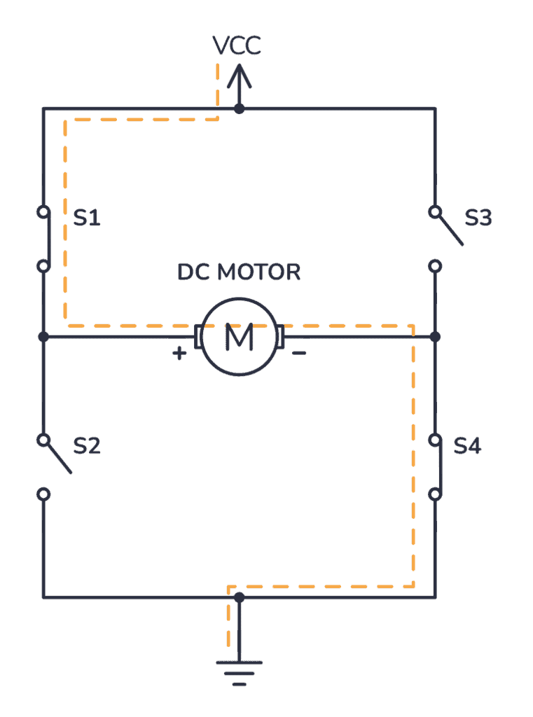
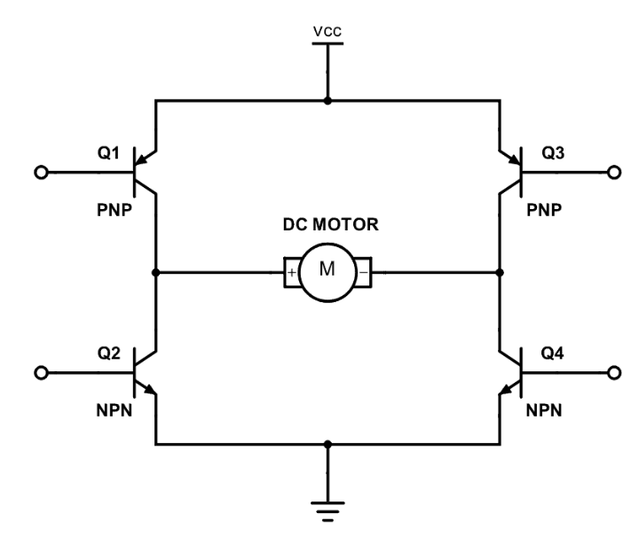
Let’s dive a bit deeper into how these H bridges work. As seen in figure 7, a basic implementation of the H bridge is just four switches, and you keep two switches closed and the other two open to control the direction of the motor. In figure 7, we close switches 1 and 4, which cause conventional current to flow from the + to the - terminal of the motor, and this will cause the motor to spin in a specific direction. If we close switches 2 and 3 instead and have 1 and 4 open, then the conventional current will flow from the - to the + terminal of the motor and will cause the motor to spin in the opposite direction. Transistors can act as switches, so we will replace the switches in figure 7 with transistors as seen in figure 8 so we can bias the transistors' base terminal to act as a switch that we can control electrically with our MCU. There is a whole art to picking the correct transistors with the correct current rating and different saturation and cutoff regions. However, we just used the L9110 H bridge to abstract from all the lower-level hardware and use something that will work and avoid the extra unnecessary annoying debugging. We only want current to flow one direction or the other direction through the motor (or, in other words, only have switches 1 and 4 closed or 3 and 2 closed). If all the switches were closed, then we would short power to ground, which is a big no-no. This is another reason to use an H-bridge IC instead of trying to build one from scratch because the ICs have a lot of built-in safety features to combat misuse/misimplementation. We will discuss this more in the software section of the report, but since we want to only have one set of switches on at a time, we will always send two PWM waves from the MCU to IA and IB of the H-bridge IC as seen in schematic 1, but one of the PWM waves will be “off.” So essentially what this means is that one PWM wave will have a nonzero duty cycle for how fast we want the motor to spin, and then the other PWM wave will have a 0% duty cycle so that it is essentially off to avoid the issue of all the transistors that act as switches being closed and shorting power to ground. This will allow us to spin the motor in one direction, and if we want to spin the motor in the other direction, we just swap the duty cycles so that the one that had a nonzero duty cycle now has a 0% duty cycle. Each motor has its own H bridge as seen in schematic 1 so that we can have each motor go in its own direction and speed.
Motor control circuit assembly
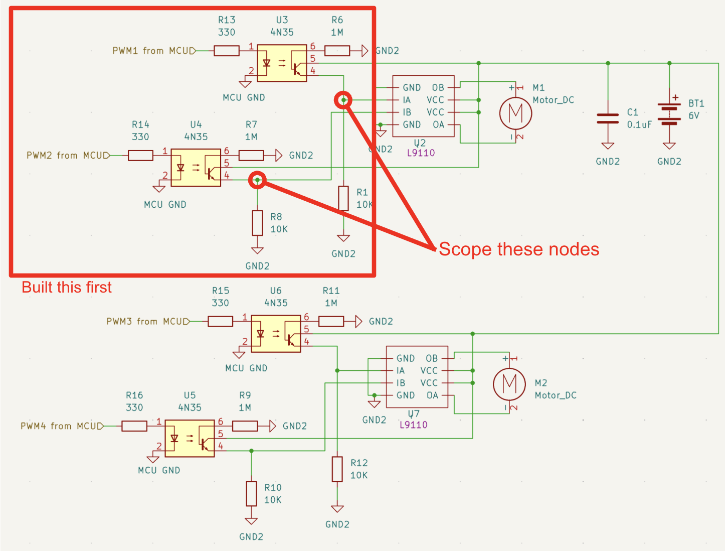
Now that we have a good understanding of how the motor control circuit functions, let’s walk through the assembly of the motor control circuit. When building the motor control circuit, it is important to take an iterative approach and build parts of the circuit, test them, verify they are behaving as expected, and then build the next part of the circuit. This idea is illustrated in schematic 2. The reason we took this iterative approach is because, for one, we are soldering these components on a protoboard, so if we make a mistake, it is easier to clean up the mistake early on since desoldering is a hassle. Additionally, for complex circuits or for circuits with multiple subcircuits like the motor control circuit in schematic 1, if your circuit does not work, it is hard to determine what the source of the error is. It is still possible to section off parts and debug the circuit with a scope, but it is better to just ensure each subcircuit works by itself first before continuing to the next section. As seen in schematic 1, we compose the motor circuit into multiple subcircuits (just different sections of the whole circuit depicted in schematic 1) so that we can easily reference different parts of the motor control circuit in this report.
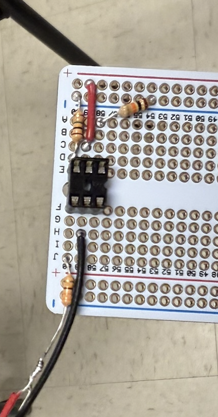
So, we first soldered subcircuit 1 in schematic 1, and you can see the result of this soldering in figure 9. You can see that we used a DIP socket so that we can slot in the 4N35 optoisolator. The reason for this is because previous students have blown out the LED in this optoisolator IC, and so rather than desoldering and soldering a new IC each time we accidentally blow it out, we can just take it out of the DIP socket and easily replace it with another IC. However, this is unlikely to happen because we have a 330-ohm current-limiting resistor in series with the LED. At the same time, it is unlikely that the noise generated by these small motors would damage the MCU in practice. Nevertheless, we still use the optoisolators because it is always better to be a safe engineer and take the proper precautions.
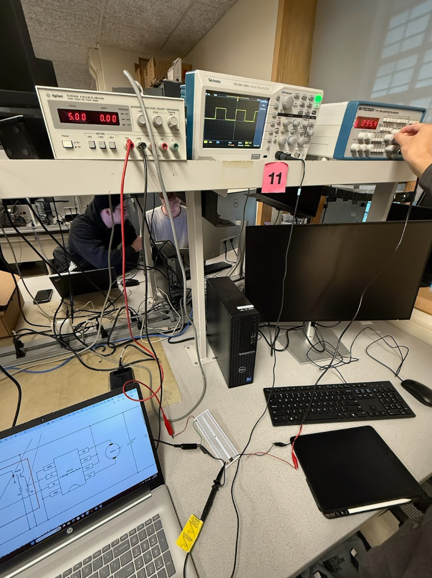
We built each subcircuit in schematic 1 and tested each one. The idea was to build subcircuit 1, scope it, and then observe the output to ensure its functionality. Then do the same for subcircuits 2, 3, and 4. The testing and verification of these subcircuits will be discussed in more detail in the results section of this report. Once we verified that subcircuits 1, 2, 3, and 4 operate as intended, we would construct subcircuits 5 and 6 and use the function generator to spin the motors at different speeds (controlled by the duty cycle) and different directions (based on PWM1 or PWM2 and PWM3 or PWM4 having the nonzero duty cycle and the other having a 0% duty cycle). It is important to ensure that for each H-bridge only one input (IA or IB) gets a nonzero duty cycle. Below is a video demonstrating us testing the motors with the power supply set to 5V to replace BT1 in schematic 1, and the motors are attached to OB and OA of their own H-bridge using screw terminals. Specifically for the video below, “PWM2 from MCU” and “PWM4 from MCU” share the function generator output, and also their “MCU GND” is shared with the common ground of the function generator. The MCU GND of subcircuits 1 and 3 also share the same common ground of the function generator, but also “PWM1 from MCU” and “PWM3 from MCU” share the common ground of the function generator, so the voltage difference between terminals 1 and 2 of the optoisolators in subcircuits 1 and 3 is 0 so that IA of both H bridges receives a duty cycle of 0% to prevent shorting power to ground since IB of both H bridges is getting the nonzero duty cycle. The video shows us just varying the duty cycle, and you can see the motors spin in the same direction, just with variable speed, as we adjust the duty cycle in real time. When the motors stop spinning, this is when the duty cycle % is not large enough to have the motors spin. The motors require a minimum duty cycle to start spinning, which we will discuss later. We also show a similar video with just one motor attached. As a quick aside, the power source for the motor control circuit depicted as BT1 in schematic 1 was generated by four double AA reachargeable batteries in series for a total of 4.8V. schematic 1 does label it as 6V, but those were older plans and 4.8V was closer to what the motors could run at (suggested voltage of around 4.5V).
RP2040 and IMU circuit design
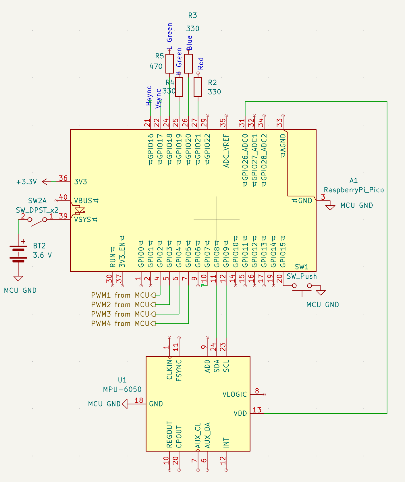
We shall now delve into the design of the RP2040 and IMU circuit, as shown in schematic 3, after fully explaining the design and assembly of the motor control circuit. The first thing to note is the BT2, which represents the power source for the RP2040. We want a separate power source from what is used for the motor control circuit; otherwise, that would defeat the purpose of the opto-isolators. The 3.6V is generated by three AA rechargeable batteries in series and is connected to VSYS via a kill switch. VSYS can be used to power the MCU from the data sheet, and the kill switch is there so that we can disconnect the power to the RP2040 if something goes wrong.
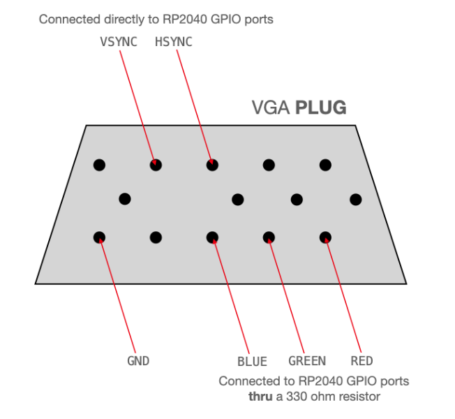
Then for GPIOs 16-21 we have pinouts for the VGA display IC, which we temporarily used to tune our complementary filter. We will discuss this more in the software section, but we won’t go into too much detail since it was only used as an intermediary step to debug our complementary filter and then never used again. To connect the VGA screen with our microcontroller, we were given a VGA breakout board, which ensured that the VGA control signals were hooked up to the correct microcontroller GPIO pins and resistors. Figure 10 shows 6 pins on the VGA plug, which would be needed for us to drive the display: Hsync is connected to GPIO 16, Vsync to GPIO 17, the low and high bits of the green signal to GPIOs 18 and 19, blue to GPIO 20, red to GPIO 21, and finally ground. Since we used 2 GPIO pins for green and 1 for blue and red (and each pin gives us 1 bit), this gave us a 4-bit color output. We chose a 330 ohm resistor for the high bit and 470 ohm for the high bit, so together they form a voltage divider to maintain the same output voltage for the display (0-0.7V), already taking into account the 70 ohm grounded resistor in the display. This description of the VGA screen interface is very similar to how we described it in labs 2 and 3 because we reused the hardware. We give credit to our lab 3.
Similarly to lab 3, we also used the MPU-6050, an IMU unit with enough accuracy to suit our needs. The sensor uses the I2C communication protocol, so we connected the IMU to the MCU with 4 connections: from ground to the IMU’s GND, from 3.3 volts to the IMU’s VIN, from GPIO 8 to the IMU’s SDA, and from GPIO 9 to the IMU’s SCL. We will discuss the software sides of things in the software section, but for now note that this IMU has a 3-axis gyroscope and accelerometer. This circuit was placed at the top of the robot to be away from all the electrical noise of the motors and motor control circuit.
Software Design
General setup
The general setup closely follows our setup for lab 3, except for the fact that we now have 2 motors who each have two PWM channels for going forward and backward. The general structure of our code is simple. We have a main function which sets up all the peripherals such as the I2C IMU, PWMs, and GPIOs. For the IMU, we decided to power it from the GPIO pin so that we could reset it every time we boot so that a failed transaction does not hang our code. Therefore, in addition to the usual I2C configuration, we also set the drive current of the IMU power GPIO pin to 12mA and then power cycle it. Then we set up the PWM configuration by making GPIO allocated to PWM and then setting up the ISR so that we can update the PWM at 1kHz. All the configurations like the wrap and clock division are set. We also set up the serial input thread to run on core 0.
ISR
The ISR holds the logic for the complementary filter described below. Here in the ISR we calculate the current angle by means of the complementary filter, and we do our PID control calculations here to generate a motor control input. These calculations must occur at a frequency of 1 kHz, which is why we put it in an ISR so that we can meet these high-priority strict timing requirements. The reason we chose 1 kHz is because, like everything in control engineering, it is a balancing act. This frequency is fast enough for the PID to update fast enough to get to the angle we want (control logic), but it is also slow enough for the PWM square wave to look like an average signal to the motor.
In order to control the speed of the motor, we use a PWM signal to modulate the duty cycle of a square wave being sent to the motor indirectly via the opto-isolator. Since we have 2 independent motors which require separate PWM signals for going forward and backward (and only one can be non-zero at a time), we need to set 4 PWM channels each time the ISR is called. Each PWM output was configured with a wrap value of 5000 and a clock divider of 25 in order to give us a 1 kHz control frequency.
Generating PWM
In order to control the speed of the motor, we use a PWM signal to modulate the duty cycle of a square wave being sent to the motor indirectly via the opto-isolator. GPIO 4 was configured as PWM output with a wrap value of 5000 and a clock divider of 25. The combination of these two values with the system clock is what matters and must give us the 1 kHz timing. You can change these values around, which will affect the granularity of our controller. We left the default values because it was enough granularity for us. This triggers an interrupt service routine at a frequency of 1 kHz, which allows the IMU values to update fast enough to give us a responsive PID controller. We have 4 PWM channels and even though each output must share the same freqeuncy it is ok because they all run at 1 kHz and we can still independently set the duty cycle and direction.
IMU and Motor Communication
In order to communicate with the IMU, we used the I2C protocol, which operates in a controller-peripheral configuration where the RP2040 acts as the controller and the MPU6050 as the peripheral. I2C protocol is a two wire serial communication bus consisting of a clock line (SCL on GPIO 9) and a data line (SDA on GPIO 8). Both of the I2C data lines have pull-up resistors that can keep them at an idle high state when no communication is occurring. Communication begins with a start condition where the master pulls SDA low while SCL remains high. The master then generates clock pulses to transmit the 7-bit peripheral address. Data on SDA is valid when SCL is high and changes when SCL is low. Each 8-bit data frame is followed by an acknowledgement bit from the receiving device. Communication ends with a stop condition where SDA transitions from low to high while SCL remains high. We used library functions in imu_demo.c to interface with the MPU6050. The I2C peripheral was initialized, and GPIO pins were configured for I2C functionality. The MPU6050 was reset, and we continuously polled raw measurements within our PWM interrupt service routine.
Complementary Filter, PID Algorithm, and Tuning
We tuned our complimentary filter code from last time in lab 3 and just switched the axis. We made sure to also test it with the VGA to ensure it functioned correctly. The only difference from lab 3 is that we used small angle approximation and thus no longer needed to filter out the acceleration measurements.
The IMU has both an accelerometer and a gyroscope, each with its pros and cons. We will use data from both sensors in order to estimate our current angle. The good thing about the accelerometer is that it measures the vector pointing in the same direction of gravity, so the measurements do not accumulate bias and are zero mean. However, the measurements are very noisy, especially when the fan is running, which adds a zero-mean Gaussian white noise with a large variance. This is because when the robot is on, it vibrates. Since the robot can only recover from angles between -10 and +10 degrees, we can use the small angle approximation to simplify our calculations. The gyroscope tells us about angular weight/velocity (deg/sec). The good thing about the gyroscope is that over short periods of time, Euler integrating the angular velocity to get the current angle is pretty accurate due to the low noise compared to the accelerometer. However, over long periods of time this leads to a large bias accumulating in the gyroscope measurements due to gyro drift. We use the complementary filter illustrated below to get the best of two worlds while avoiding the negative parts of the accelerometer and gyroscope.
The filter has 4 main steps:
1)Gather accelerometer and gyro measurements
2)Compute the accelerometer angle using the small angle approximation
3)Compute the change in gyro angle summed with the previous complimentary angle to get an updated estimate on where the gyro thinks the angle is currently
4)Compute the new complementary angle as a weighted average of the 2 above angles- 99% weight to the gyro and 1% weight to the accelerometer
Once we had the complementary angle, we used the PID control algorithm to change the motor PWM signal so we could move the robot to any target angle. PID stands for proportional, integral, and derivative, and each of the terms plays an important role. The proportional term multiplies the error from the current angle to the target angle (error=target-current angle) by a constant (Kp) and plays an important role in how aggressive and snappy the controller is when moving to a new target angle. The derivative term multiplies the change in angle (so the raw gyro value) by a constant (Kd) and plays an important role in dampening the robot’s oscillations from the P term to prevent it from overshooting its target. The integral term multiplies the current sum of angle error (it integrates previous error) by a constant (Ki) and plays an important role in eliminating the steady-state error because of the order of our system, which causes the robot to come to rest a few degrees below the target angle. We need to be careful about the I term, though, since it destabilizes the system by introducing phase, especially if we allow the sum of error to grow too large. We also have to deal with integrator windup.
Finally, the 3 PID terms are added up to get the total motor control input. This value is then passed through 2 min/max checks to clamp it between the maximum absolute duty cycle that the motors can provide, which we found to be +/- 2100. We also noticed that the motors have a minimum duty cycle required in order to overcome the static friction of the gearbox and start moving. We found that this to be +/- 1900 when the motors are loaded, so when the robot is placed upright on the table. During tuning we also noticed that the robot was biased in the negative direction due to an uneven weight distribution. As a result, we added code which set the target position to be slightly more in the positive direction when the IMU detected that the robot’s angle was less than 0.
Additionally, we wanted to be able to support moving the robot forward and backward. In order to implement this, we found that the easiest way was to set the robot’s target angle to be either in the positive or negative direction for a 150 ms before resetting it to 0 degrees, which is the stable position.
We tuned the PID controller in a systematic way based on observations as discussed in class. We do not want to tune all the parameters at once because that is too many changing variables at once. First we played around with our Kp gain value. We didn't have much success so then we added Kd and kept increasing both gains until it was stable for most of the time but still slightly off (the robot would eventually tip over). Eventually when we added Ki that closed the steady state error and we were able to fully balance our robot.
Moving Forwards and Backwards
To move forwards the idea was to set the target angle a little bit positive so that the robot would purposely displace itself fowards and then we would then set the target angle to 0 to restabalize. By taking incrementing steps forward we are able to slowly go forwards while maintaining our balance. A really similar idea is used to go backwards, we just set the target angle in the opposite direction. We had to play around with how agressive we set the target angle and for how long we set it. If we set it to too big of a target angle change or for too long our robot would not be able to recover itself and just fall over. We were able to vary the time we set the target angle to a specific angle with multiple counter variables that would increment in the ISR since the ISR ran at 1 kHz then each counter incrementing would be 1 ms.
Previous iterations
Initial Strucutral Design
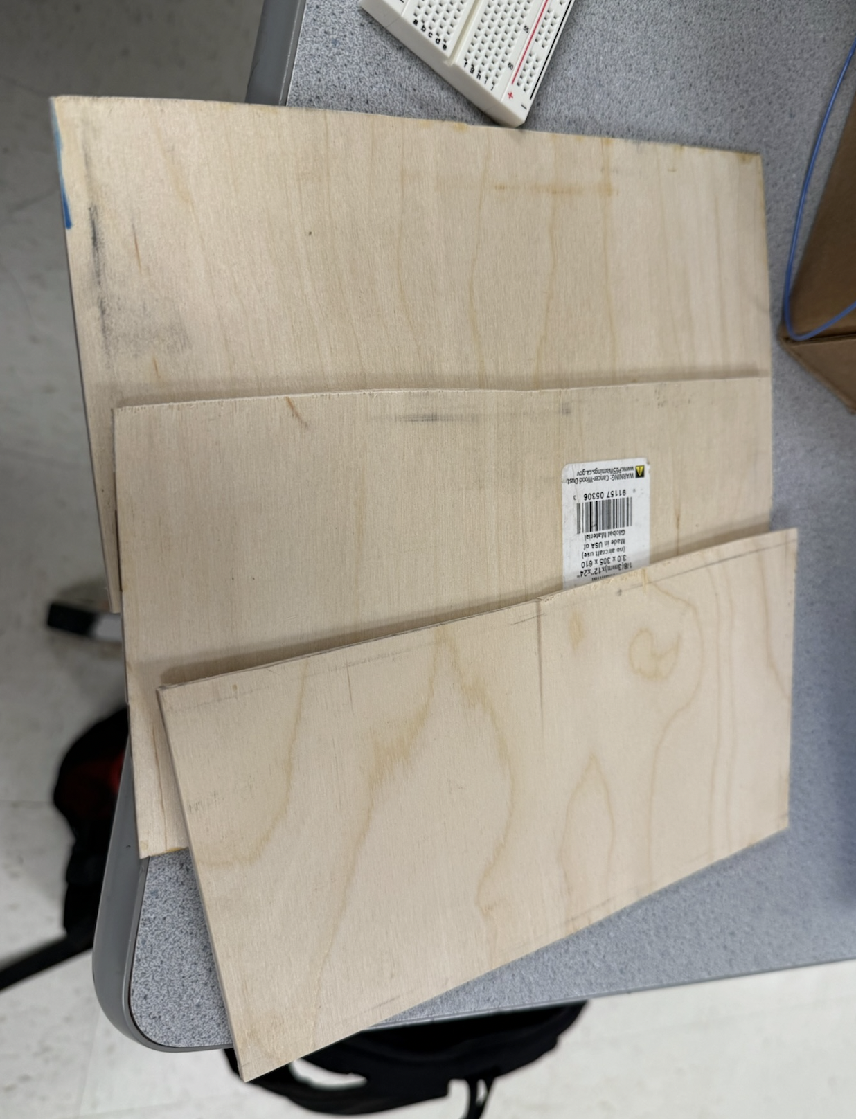
In this section, we will discuss things that we tried but in the end did not work. For our first structural design, we attempted to make each layer/platform of the robot out of some sort of plywood that we found in the lab. We used a bandsaw to cut the wood into three evenly sized platforms, as seen in figure 12. We realized that they were too big, so we downsized them by scoring the wood and then breaking the pieces of wood in half. We then attempted to drill holes into the four corners so we could slide dowels through the holes, but while drilling, it fractured the wood. We decided this wasn’t the most reliable and durable option, so we switched to Legos. There were Legos lying around in the lab, and they were easy to work with, and we designed a structure out of the Legos that was fairly rigid. The holes in the Legos were just wide enough to fit the wooden dowels and tight enough to keep the dowels in place. The way the Legos were put together was described in more detail in the structural design section above. The Legos were also easier to make design iterations on and change the shape compared to the wood.
Powering the MCU with a coin cell battery
For a long time we pondered how to power the MCU. We were already powering the two DC motors with four AA rechargeable batteries with a max capacity of 1.2V each, so a total of 4.8V, which is more than good enough for the 4.5V suggested for the motors. Both motors shared these four batteries, as seen in schematic 1. 4.8V is safe to provide to the MCU for power, but we did not want to use the same four AA rechargeable batteries since that would defeat the purpose of the optoisolators because then the motors would share the same power supply (so power and ground lines) as the MCU, and we would lose our electrical isolation. So, we opted to use a coin cell battery. The reason for a coin cell battery is because of its compact size and light weight. So if we added it, it wouldn’t drastically change our system, and we wouldn’t have to retune our PID parameters. We didn’t have a coin cell battery holder, so we had a janky method of electrically taping two wires to both sides of the battery. One wire from the positive terminal of the coin cell went to VSYS of the RP2040, and the other wire from the negative terminal of the coin cell went to the ground of the RP2040. There were many issues with this. First, sometimes we would forget to cut the connection (with the kill switch) from the button battery to the MCU when programming it. This is bad because when we plug in the USB to the RP2040 to program it, it also provides power to the MCU, and the MCU will try to “charge” the power supply attached to the VSYS, which sends current into the coin cell battery, as seen in schematic 4, causing it to heat up, which is very dangerous. Also, the capacity of our coin cell was also 225 mAh, which won’t last too long. Another issue with the coin cell is we found that the MCU was behaving weirdly. As an example, it would randomly spin the motors at full speed. The system would behave erratically under load because the coin cell battery had too low of a voltage and did not output enough current consistently, which actually affects the MCU clock speed. The coin cell battery can provide around 15-30 mA and around 3 V, which is not good enough for the pico. Especially with the need to use I2C communication with our IMU and run the control loop at a consistent frequency of 1 kHz, the coin cell battery was just too unreliable. Our solution to this was to use three AA rechargeable batteries in series with a total capacity of 3.6 V, and this provided enough voltage and current to VSYS, and our robot can finally run completely untethered! The current supply of the three rechargeable batteries was also more consistent and reliable. Also, since the batteries are rechargeable, we need not worry about cutting the power with the kill switch anymore when plugging in the USB because it is ok to send current into these batteries because that is how they recharge. We placed it on the middle layer to help distribute the weight more as well as still keep the center of mass towards the top of the robot.
Breadboard wires continuously falling out
At first we used a breadboard for the top layer of the robot that was used to hold the MCU circuit that sent out the PWM signals and interfaced with the IMU sensor. However, the wires kept falling out of the PWM signals, which was very annoying to put back into the breadboard each time. Our solution was to solder everything onto a protoboard so the connections were more permanent. We exercised good practice by keeping the original working version with the breadboard and reproducing the circuit on the protoboard so we always had the breadboard version if something went wrong with soldering the protoboard. The protoboard helped get rid of the delays in replugging in all the PWM wires each time they fell out and sped up our tuning process significantly. Below you can see the before and after of the MCU circuit from breadboard to protoboard.
Saftey tether for robot
We originally thought of having a safety string for the robot that we could use to catch the robot if it falls over. However, this string was more of a hassle than a useful tool, so we removed it. It would get tangled up and get in the way. Instead, we just put our hands cautiously near the robot to catch it if it was about to fall.
To improve user experience, we wanted to implement wireless UART via infrared. The idea was that the robot would have the receiver, and we would have another RP2040 hooked up to a transmitter, and this RP2040 with the transmitter would act as the remote, which would be connected to our computer. We would send serial messages to this remote RP2040, and then this RP2040 would transmit via IR to the robot’s MCU, where it has a receiver. We got a prototype working with breadboarding and then moved on to solder the components to the MCU protoboard circuit of the robot. However, it was harder to implement than we thought and needed a lot more data cleaning than we originally thought. We ran out of time, so we opted to just use direct serial communication via the serial monitor if we wanted to communicate with and debug the robot. The robot has to be tethered then, but it is ok for debugging purposes. For the demo, we had a preprogrammed demo script as described in the software section so the robot could be completely untethered. The original IR idea came from the course website.
Stair climbing and turning in place
Just in case we finished our primary goals/main specification early, we had some reach goals in place for fun. We wanted to tune our system so that it could still balance while going down a ramp or stairs. We would have to iterate on our mechanical design to be robust enough and possibly invest in better motors. We could barely disrupt our robot as is because of the physical constraints of our motors: they simply did not have enough torque. We know they did not have enough torque because a lot of the times when debugging our system through the serial monitor, the PID control was outputting the max value. Instead of this ambitious goal, we focused on perfecting the balancing on flat surfaces since this was already challenging enough, met our specifications, and we were able to finish it in time for demo day. We also wanted to turn in place, but this is a more complex problem than moving forwards or backwards and may even require another sensor since the IMU lacks information to know if it is turning in place. This is because if the robot is perfectly balanced and turns in place, the gravity vector pointing down will always be the same so it will look like the robot is staying in place even if it is turning in place. We could have gotten motors with encoders to know it has turned a certain angle, but we didn’t have time to attempt this problem. We can control the motors to be any speed and direction independently, though, so it is possible to do; we just did not have enough time.
Height of top platform
This was discussed more in the hardware section, but originally we had the top platform with most of the mass really high from the base of the robot. The intent was so that we would have less angular acceleration and thus more time to self-correct the robot. However, this means you also have more torque, and because our motors did not have enough torque to support the mass being so high up, we had to lower the top platform in order to lower the amount of torque needed to correct the robot. We would need to move the motors faster and react faster, but this is ok because we already have decently fast motors and a fast control loop. Of course we cannot move the top platform too low to the base; otherwise our motors would not be fast enough to correct for when it starts to tip over. We found the right height by moving the top platform up and down until we had a good balance of torque and speed needed from the motors, and then we hot-glued the top platform in place to guarantee it wouldn’t slide along the dowels and change position. We want to always keep as many things of our system constant as possible so there is less variability and it is easier to focus on the main control problem.
Smaller motors with more torque and speed
Finally, we bought motors with higher torque and speed ratings. We attached tape to make it easier to see visually that one motor is faster than the other even though the ratings on the datasheets do talk about the rpm and torque ratings. However, we decided not to use these motors because they were small and hard to attach to the Legos. The hobbyist motors we wound up using were very easy to attach to the Lego chassis, as explained in the hardware section.
AI Use
For both the hardware and software design we did not use any AI. The only outside resource we used was QuillBot to check the grammar of our report.
Results of the design
Collected data
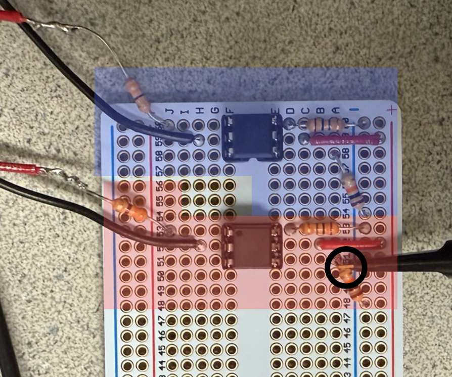
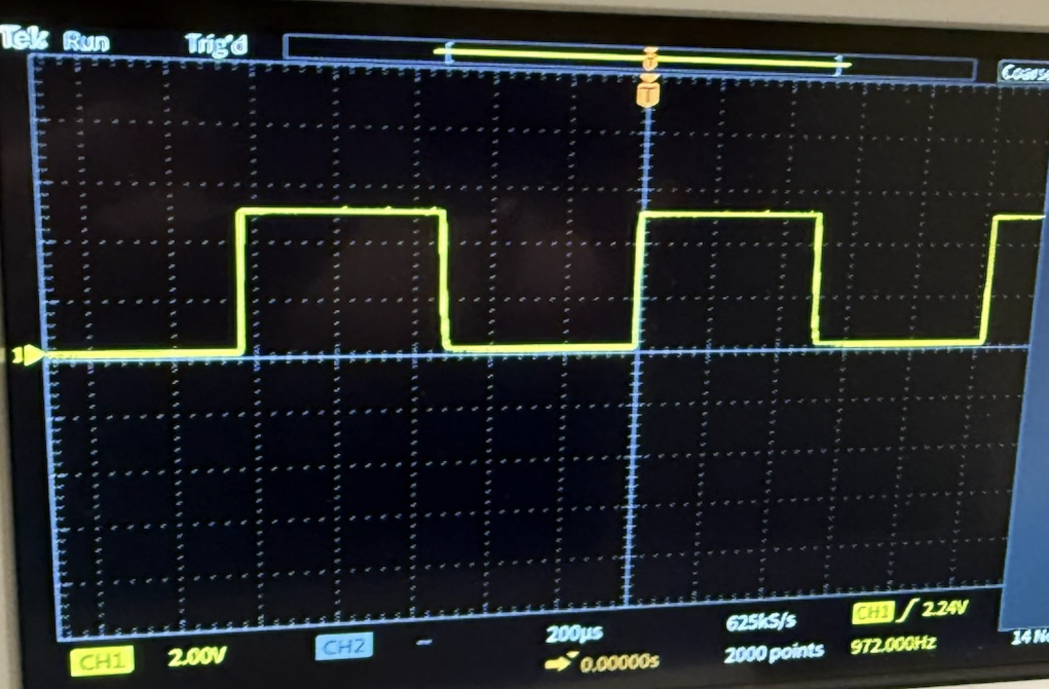
In this section we will discuss any and all test data, scope traces, waveforms, etc. collected while doing this project. First we will discuss more about the testing and verification of the subcircuits of the motor control circuit found in schematic 1. As seen in schematic 2, we scope the nodes circled in red to ensure that each subcircuit works as we build each one since we took an iterative approach to constructing the motor control circuit. As an example, after building subcircuit 2 seen in schematic 1 and figurescope, we scoped the IB terminal of the L9110 IC (top node of the 10kohm resistor) and then got the trace seen in figure 14. Nothing is connected to the “MCU GND” or “PWM1 from MCU” from subcircuit 1 in schematic 1, but we do attach the function generator to “MCU GND” and “PWM2 from MCU" from subcircuit 2 in schematic 1. We configure the function generator to send out a 1 kHz square wave with an amplitude of 5V and an arbitrary duty cycle. We then varied the duty cycle and watched it change in real time on the scope. You can see in figure 14 the amplitude is around 5V and has a frequency of 972 Hz, which is about 1 kHz. We didn’t include the cursors in Figure 14, but visually the duty cycle looks to be about 50%, which is around what we set it to be for the function generator for this picture.
Speed of execution
The control loop frequency of our PID controller is 1 kHz, and this is also the frequency of the PWM sent to our motors. As seen in lab 3, the IMU updates fast enough to keep up with the control loop frequency, and as seen in the demo video, it responds quickly to slight disturbances. If the robot is pushed from its center stable position, it is able to quickly stabilize. The robot does jitter due to the high derivative term and also due to the fact that the robot is in a constant state of instability. When the robot is told to go forwards or backwards, it does in a reasonable amount of time; we are just careful in how fast we move forwards or backwards so we do not risk falling over and not being able to recover. To reach the control loop frequency, we don't do too many floating-point calculations, and honestly, 1 kHz is not fast enough to need floating-point math.
Accuracy
Our robot was able to balance itself for more than 5 minutes, as seen in the demo video at the top of this webpage. While it is a bit shaky, this is due to there being no positioning of the robot where it can balance without the help of the motors. Thus, it is in a constant state of instability and must constantly move to stabilize itself. For being able to stay stable for this length of time is a testament to how well and reliably our robot can balance. We can also set target angles very specifically because of our tuned complementary filter down to the degree. This is useful for making the robot go forwards and backwards. Right now the robot only goes forwards and backwards for a set amount of time. Future work can be done, like using encoded motors so we can have more accurate commands and tell the robot to go forwards x inches instead of for x seconds.
Saftey Considerations
Electrical safety
We were using AA rechargeable batteries, and the max voltage was for the motors at 4.8V, which is nowhere near the realm of high voltage, so we need not worry about the dangers of high-voltage systems. We use optoisolators to electrically isolate the motors from the MCU. We also made sure to heat shrink exposed soldering so that nothing would short together. We placed the two protoboards on separate layers to avoid noise disrupting the IMU. We had a kill switch for the power going to the MCU so we could cut the power to the MCU if the robot went out of control. We also had two sets of batteries/power supplies, one for the MCU and one for the motors, so that we wouldn’t void the effect of the optoisolators. For the batteries we also followed the IEC 61951-2 standards for basic safety guidelines, like preventing overcharging the batteries or not mixing the batteries with other brands. We also went over UL 2054 battery standards for both non-rechargebale and rechargeable batteries.For local motor vehicle codes, we will be running the robot in a private space and not be driving fast enough to take these codes into consideration.
Software safety
We had a cap on the max duty cycle the PWM signals could output so that we did not overdrive the motors. We also made sure that one of the inputs of the H bridge always received a duty cycle of 0% from the MCU to avoid shorting power to ground. We also implemented some code to prevent integrator windup to prevent the robot from behaving sporadically and hurting someone.
Usability by our team and other people
The main way to interface with the robot is to connect the MCU to our computer via the debugger and communicate with it through the serial monitor via UART. We have a simple back-and-forth interface with the serial monitor, which will tell you the commands to put in to change features of the robot. For example, if you type in the letter "p," it will then prompt you to enter a value to change the Kp value of our PID controller, which is helpful for debugging purposes. You can also type in "m," and it will prompt you to put in a negative, positive, or zero number to go backwards, forwards, or stay in its stable position, respectively. This was more than enough for our team to debug the system and playtest it. We had one person inputting commands into the serial monitor to tune the PID controller while another person observed the changes and made sure the robot did not fall over. One thing to note is that the tension of the USB cable did affect the movement of the robot. However, for other people this may not be the best option because the robot is tethered and restricted. Also, for people who don’t know what a PID controller is, some of the controls would be useless to them. This was the motivation to implement IR control with a simple button interface for forwards, backwards, and balance-in-place modes, but unfortunately we could not get it to work in time as explained above in the previous iterations sections. Another way we could have made it more interactable would be adding more sensors, like a distance sensor, so it could navigate obstacles. Unfortunately we did not have time for this either.
Conclusions
Meeting Specifications and Future improvements
Our self-balancing robot successfully met our primary goal of maintaining upright balance and executing the programmed motion sequences of going forwards and backwards for the demo. We are also proud of how long it can remain balanced and how it can also recover from slight disturbances.
Looking at our smaller goals to get the whole thing working, the complementary filter effectively used gyroscope and accelerometer data to provide a stable and accurate angle estimate. After many iterative tests of the PID gains, we got a tuned PID controller that is stable and snappy. We did a good job with our mechanical design because if we didn't put the majority of the mass at the right height, we would not have been able to balance it no matter what our PID gain terms were.
However, we also encountered challenges that we would have addressed differently next time. The infrared remote control attempt was ultimately abandoned at the end due to lack of time. With more time, we would have created software to clean and process the bits so the UART communication would be reliable because this would be a huge boost in the usability of the robot. We would also like to consider using a custom PCB rather than a protoboard to make the system more compact and reliable. We could also explore more advanced control algorithms like LQR or any other model predictive control to compare performance against PID. We would also want to try implementing our reach goals, like turning in place and balancing while going up a ramp or down stairs. Another thing we might have done differently is model our robot chassis in CAD so it would be more durable than the Legos we have now. We also would have gotten motors with more torque so we could be more agressive with our controller.
Conformance to Applicable Standards
Our design conforms to several applicable standards for best practices. For electrical safety, we used low-voltage power supplies with 3x AA providing 4.5V and 4x AA providing 4.8V, well below any shock hazard threshold. The motor control circuit uses optoisolators to provide electrical isolation between the motors and the MCU.
On the software side, we followed the coding practices established in the ECE 4760 course syllabus, referencing original sources where we adapted code from Lab 3.
Intellectual Property Considerations
We reused some of our code elements from ECE 4760 Lab 3, for which we also got some of the code from the course repo as starting points. Specifically, we adapted the complementary filter implementation, PID control structure, and I2C communication setup. We used the protothread library provided by the course. We did not use code from any other public domain. We used publicly available datasheets, including Raspberry Pi Foundation for the RP2040, Adafruit for the MPU-6050 IMU, Elecrow for the L9110 H-bridge, and Broadcom for the 4N35 datasheet. These datasheets are provided by manufacturers for design references and are public domain technical documentation. We are not reverse-engineering any commercial product. While commercial self-balancing robots exist and are covered by patents, we implemented our own design. We do not intend to sell our project, and it was only for educational purposes. We didn't sign any NDAs to get any of our components, and we bought everything from public retailers like DigiKey and Amazon. There is not an opportunity to patent this because it has been done in different ways before and is nothing new.
Appendix A: Permissions
The group approves this report for inclusion on the course website.
The group approves the video for inclusion on the course youtube channel.
Appendix B: Commented C Code
/**
 * Aidan Chan (amc564@cornell.edu), Jonathan Ma (jjm498@cornell.edu), Ayushi Raina (ar929@cornell.edu)
 * IMU code inspired by V. Hunter Adams (vha3@cornell.edu)
 * Self-balancing two-wheeled robot
 */

// Include standard libraries
#include <math.h>
#include <stdio.h>
#include <stdlib.h>
#include <string.h>
#include <time.h>
// Include PICO libraries
#include "pico/multicore.h"
#include "pico/stdlib.h"
// Include hardware libraries
#include "hardware/adc.h"
#include "hardware/clocks.h"
#include "hardware/dma.h"
#include "hardware/i2c.h"
#include "hardware/irq.h"
#include "hardware/pio.h"
#include "hardware/pwm.h"
#include "hardware/uart.h"
// Include custom libraries
#include "mpu6050.h" // for the imu
#include "pt_cornell_rp2040_v1_4.h" // for protothreads
// #include "vga16_graphics_v2.h" // used when debugging the complementary filter with the VGA display

// Some macros for max/min/abs
#define min(a, b) ((a < b) ? a : b)
#define max(a, b) ((a < b) ? b : a)
#define abs(a) ((a > 0) ? a : -a)

// GPIO for PWM
#define PWM_L_FW 4 // PWM for the left motor going forwards
#define PWM_L_BW 5 // PWM for the left motor going backwards
#define PWM_R_FW 6 // PWM for the right motor going forwards
#define PWM_R_BW 7 // PWM for the right motor going backwards

// Some paramters for PWM so that it has a frequency of 1kHz
#define WRAPVAL 5000
#define CLKDIV 25.0
uint slice_num_l;
uint slice_num_r;

// Min and max motor control values
#define MIN_DUTY_CYCLE 1900 // minimmum duty cycle to get the motors moving on ground
#define MAX_DUTY_CYCLE 4000
#define MAX_CTRL 2100 // 4000-1900 = 2100, actual range of our PID control output
#define MIN_CTRL -2100

// Bias for the z-axis acceleration
#define az_bias float2fix15(0.22)

// Starting time to keep track of when the angle sequence playback started
static int begin_time;

typedef enum {
    FORWARDS,
    BACKWARDS,
    STABLE
} direction_state_t;
volatile direction_state_t current_direction = STABLE; // assume default not pressed

// Arrays in which raw measurements will be stored
fix15 acceleration[3], gyro[3];
fix15 complementary_angle;
fix15 accel_angle, gyro_angle;

volatile int target_angle = 0; // always want target angle to be 0 because that is it facing upwards

// Character array for VGA graph text
char screentext[40];
char str_buffer[256] = {0}; // string buffer for the PID text to display on the screen

// Draw speed for VGA graph
int threshold = 250;

// Semaphores
static struct pt_sem vga_semaphore;
static struct pt_sem serial_semaphore;

// PWM duty cycle
volatile int control_l = 0;
volatile int control_r = 0;
volatile int filtered_control = 0;
volatile int filtered_old_control = 0;

// PID parameters
volatile float kp = 890;
volatile float kd = 420;
volatile float ki = 10; // next time tune look at georige suggestions

volatile int PID_output;

float error_sum = 0;
float error_sum_max = 2000;

volatile int counter = 0;
volatile int global_counter = 0;

#define IMU_POWER 26
#define LED_PIN 25
#define UART_ID uart0
#define UART_RX_PIN 13

const int positive_bias_correction = -11;
const int negative_bias_correction = 3;
const int true_zero_correction = -4;

// Interrupt service routine
void on_pwm_wrap() {

    // Clear the interrupt flag that brought us here
    pwm_clear_irq(slice_num_l);

    // Read the IMU
    // NOTE! This is in 15.16 fixed point. Accel in g's, gyro in deg/s
    mpu6050_read_raw(acceleration, gyro);

    // Complementary filter
    // Don't need ax because we are just rotating about the x axis
    fix15 ax = acceleration[0];
    fix15 az = acceleration[2] + az_bias;

    // tan = opposite/adjacent = a_z/-a_x (atan2 takes args in reverse order)
    accel_angle = multfix15(divfix(ax, az), oneeightyoverpi);

    // We are rotating about the y axis
    fix15 gy = -gyro[1];
    fix15 gyro_angle_delta = multfix15(gy, zeropt001);
    gyro_angle = complementary_angle - gyro_angle_delta;

    // Complementary angle (degrees - 15.16 fixed point)
    complementary_angle = multfix15(gyro_angle, zeropt999) + multfix15(accel_angle, zeropt001);
    if (global_counter > 19000) {
        current_direction = STABLE; // after 17 total seconds (4 seconds after backwards) stay stable forever
        gpio_put(LED_PIN, 1);
    } else if (global_counter > 15000) {
        current_direction = BACKWARDS; // after 13 total seconds (5 seconds after stable) go backwards
        gpio_put(LED_PIN, 0);
    } else if (global_counter > 8000) {
        current_direction = STABLE; // after 8 total seconds (3 seconds after stable) be stable for 5 seconds
        gpio_put(LED_PIN, 1);
    } else if (global_counter > 5000) {
        current_direction = FORWARDS; // after 5 seconds go forwards
        gpio_put(LED_PIN, 0);
    } else {
        current_direction = STABLE; // first 5 seconds be stable
        gpio_put(LED_PIN, 1);
    }

    if (current_direction == STABLE) {
        if (fix2float15(complementary_angle) >= true_zero_correction) { // prevent positive bias/lean
            target_angle = positive_bias_correction;
        } else { // address negative bias
            target_angle = negative_bias_correction;
        }
        counter = 0;
    } else {
        if (counter > 0) { // have target angle positive so go backwards
            counter++;     // do it for 200 ms (frequency of ISR is 1000times a second)
            if (counter >= 150) {
                counter = 0; // reset counter
            }
            if (current_direction == BACKWARDS) {
                target_angle = -14;
            } else if (current_direction == FORWARDS) {
                target_angle = 5;
            }
        }
        // if equal 0 then stable from the reset above and if negative it is counting to stay negative until 2 seconds has passed
        else if (counter <= 0) { // keep target angle stable for 2 seconds
            counter--;
            if (counter <= -2750) {
                counter = 1; // go back to greater than 0 so go to top conditional of going forwards a bit
            }
            // stabalization code
            if (fix2float15(complementary_angle) >= true_zero_correction) { // prevent positive bias/lean
                target_angle = positive_bias_correction;
            } else { // address negative bias
                target_angle = negative_bias_correction;
            }
        }
    }

    float error = target_angle - fix2float15(complementary_angle);

    // Accumulate and clamp error sum for integration term
    error_sum += error;
    error_sum = min(error_sum, error_sum_max);
    error_sum = max(error_sum, -error_sum_max);

    // negate PID output so robot stays upright
    PID_output = (error * kp) + fix2int15(gy) * kd + error_sum * ki;
    if (PID_output > MAX_CTRL) {
        PID_output = MAX_CTRL;
    } else if (PID_output < MIN_CTRL) {
        PID_output = MIN_CTRL;
    }
    if (PID_output >= 0) {
        PID_output += MIN_DUTY_CYCLE;
    } else {
        PID_output -= MIN_DUTY_CYCLE;
    }

    if (PID_output <= 0) {
        pwm_set_chan_level(slice_num_l, PWM_CHAN_A, PID_output);
        pwm_set_chan_level(slice_num_l, PWM_CHAN_B, 0);
        pwm_set_chan_level(slice_num_r, PWM_CHAN_A, PID_output);
        pwm_set_chan_level(slice_num_r, PWM_CHAN_B, 0);
    } else {
        pwm_set_chan_level(slice_num_l, PWM_CHAN_A, 0);
        pwm_set_chan_level(slice_num_l, PWM_CHAN_B, -PID_output);
        pwm_set_chan_level(slice_num_r, PWM_CHAN_A, 0);
        pwm_set_chan_level(slice_num_r, PWM_CHAN_B, -PID_output);
    }
    global_counter++; // update global counter each interrupt
    // Signal VGA to draw
    PT_SEM_SIGNAL(pt, &vga_semaphore);
    PT_SEM_SIGNAL(pt, &serial_semaphore);
}

// // Thread that draws to VGA display, commented out because used for debugging and not final implementation
// static PT_THREAD(protothread_vga(struct pt *pt)) {
//     // Indicate start of thread
//     PT_BEGIN(pt);
//
//     // We will start drawing at column 81
//     static int xcoord = 81;
//
//     // Rescale the measurements for display
//     static float OldRange = 500.; // (+/- 250)
//     static float NewRange = 150.; // (looks nice on VGA)
//     static float OldMin = -250.;
//     static float OldMax = 250.;
//
//     // Control rate of drawing
//     static int throttle;
//
//     // Draw the static aspects of the display
//     setTextSize(1);
//     setTextColor(WHITE);
//
//     // Draw bottom plot
//     drawHLine(75, 430, 5, CYAN);
//     drawHLine(75, 355, 5, CYAN);
//     drawHLine(75, 280, 5, CYAN);
//     drawVLine(80, 280, 150, CYAN);
//     sprintf(screentext, "0");
//     setCursor(50, 350);
//     writeString(screentext);
//     sprintf(screentext, "3500");
//     setCursor(50, 280);
//     writeString(screentext);
//
//     // Draw top plot
//     drawHLine(75, 230, 5, CYAN);
//     drawHLine(75, 155, 5, CYAN);
//     drawHLine(75, 80, 5, CYAN);
//     drawVLine(80, 80, 150, CYAN);
//     sprintf(screentext, "0");
//     setCursor(50, 150);
//     writeString(screentext);
//     sprintf(screentext, "90");
//     setCursor(45, 75);
//     writeString(screentext);
//     sprintf(screentext, "-90");
//     setCursor(45, 225);
//     writeString(screentext);
//
//     while (true) {
//         // Wait on semaphore
//         PT_SEM_WAIT(pt, &vga_semaphore);
//         // Increment drawspeed controller
//         throttle += 1;
//         // If the controller has exceeded a threshold, draw
//         if (throttle >= threshold) {
//             // Zero drawspeed controller
//             throttle = 0;
//
//             // Erase a column
//             drawVLine(xcoord, 0, 480, BLACK);
//
//             // Draw bottom  plot (multiply by 0.089 to scale from +/-3500 to +/-250)
//             // Low pass motor control signal so the graph is less noisy
//             filtered_old_control = filtered_control;
//             filtered_control = filtered_old_control + ((control_l - filtered_old_control) >> 5);
//             drawPixel(xcoord, 430 - (int)(NewRange * ((float)((filtered_control * 0.0714) - OldMin) / OldRange)), ORANGE);
//
//             // Draw top plot (multiply by 2.8  to scale from +/-90 to +/-250)
//             // drawPixel(xcoord, 230 - (int)(NewRange * ((float)((fix2float15(gyro_angle) * 2.8) - OldMin) / OldRange)), RED);
//             // drawPixel(xcoord, 230 - (int)(NewRange * ((float)((fix2float15(accel_angle) * 2.8) - OldMin) / OldRange)), GREEN);
//             drawPixel(xcoord, 230 - (int)(NewRange * ((float)((fix2float15(complementary_angle) * 2.8) - OldMin) / OldRange)), WHITE);
//             drawPixel(xcoord, 230 - (int)(NewRange * ((float)(((target_angle) * 2.8) - OldMin) / OldRange)), BLUE);
//
//             // Update horizontal cursor
//             if (xcoord < 609) {
//                 xcoord += 1;
//             } else {
//                 xcoord = 81;
//             }
//
//             // Draw PID info text on screen
//             setTextColorBig(WHITE, BLACK);
//             setCursor(10, 20);
//             sprintf(str_buffer, "Kp:  %.2f   Ki: %.2f   Kd: %.2f   Targ_ang: %d     Curr_ang: %d         ", (kp), ki, kd, target_angle, fix2int15(complementary_angle));
//             writeStringBig(str_buffer);
//         }
//     }
//     // Indicate end of thread
//     PT_END(pt);
// }

// Thread for serial monitor to debug instead of the vga
static PT_THREAD(protothread_serial_core1(struct pt *pt)) {
    // Indicate start of thread
    PT_BEGIN(pt);

    // Control rate of drawing
    static int throttle;

    while (true) {
        // Wait on semaphore
        PT_SEM_WAIT(pt, &serial_semaphore);
        // Increment drawspeed controller
        throttle += 1;
        // If the controller has exceeded a threshold, draw
        if (throttle >= threshold) {
            // Zero drawspeed controller
            throttle = 0;
            // sprintf(pt_serial_out_buffer, "current PID output: %d\n", PID_output);
            sprintf(pt_serial_out_buffer, "current angle: %f\n", fix2float15(complementary_angle));
            serial_write;
            sprintf(pt_serial_out_buffer, "target angle: %d\n", target_angle);
            serial_write;
        }
    }
    // Indicate end of thread
    PT_END(pt);
}

// User input thread for changing draw speed, PID parameters, or target angle
static PT_THREAD(protothread_serial(struct pt *pt)) {
    PT_BEGIN(pt);
    static char classifier;
    static int test_in;
    static float float_in;
    while (1) {
        sprintf(pt_serial_out_buffer, "input a command (t for timestep, p for kp, i for ki, d for kd, and a for target angle): ");
        serial_write;
        // spawn a thread to do the non-blocking serial read
        serial_read;
        // convert input string to number
        sscanf(pt_serial_in_buffer, "%c", &classifier);

        if (classifier == 'p') {
            sprintf(pt_serial_out_buffer, "kp: ");
            serial_write;
            serial_read;
            // convert input string to number
            sscanf(pt_serial_in_buffer, "%f", &float_in);
            if (float_in >= 0) {
                kp = float_in;
            }
        } else if (classifier == 'd') {
            sprintf(pt_serial_out_buffer, "kd: ");
            serial_write;
            serial_read;
            // convert input string to number
            sscanf(pt_serial_in_buffer, "%f", &float_in);
            if (float_in >= 0) {
                kd = float_in;
            }
        } else if (classifier == 'i') {
            sprintf(pt_serial_out_buffer, "ki: ");
            serial_write;
            serial_read;
            // convert input string to number
            sscanf(pt_serial_in_buffer, "%f", &float_in);
            if (float_in >= 0) {
                ki = float_in;
            }
        } else if (classifier == 'a') {
            sprintf(pt_serial_out_buffer, "target angle (-90 to 90 degrees): ");
            serial_write;
            serial_read;
            // convert input string to number
            sscanf(pt_serial_in_buffer, "%d", &test_in);
            if (test_in >= -90 && test_in <= 90) {
                target_angle = test_in;
            }
        } else if (classifier == 'm') {
            sprintf(pt_serial_out_buffer, "positive number to go forwards, negative number to go backwards, 0 to stop: ");
            serial_write;
            serial_read;
            sscanf(pt_serial_in_buffer, "%d", &test_in);
            if (test_in > 0) {
                current_direction = FORWARDS;
            } else if (test_in < 0) {
                current_direction = BACKWARDS;
            } else {
                current_direction = STABLE;
            }
        } else {
            sprintf(pt_serial_out_buffer, "invalid command");
            serial_write;
        }
    }
    PT_END(pt);
}

// Entry point for core 1
void core1_entry() {
    // pt_add_thread(protothread_vga);
    pt_add_thread(protothread_serial_core1);
    pt_schedule_start;
}

int main() {

    // Overclock
    set_sys_clock_khz(150000, true);

    // Initialize stdio
    stdio_init_all();

    // Initialize VGA
    // initVGA();

    ////////////////////////////////////////////////////////////////////////
    ///////////////////////// I2C CONFIGURATION ////////////////////////////
    // code to reset the I2C when reboot
    gpio_init(IMU_POWER);
    gpio_set_dir(IMU_POWER, GPIO_OUT);
    gpio_set_drive_strength(IMU_POWER, GPIO_DRIVE_STRENGTH_12MA);
    gpio_put(IMU_POWER, 0);
    sleep_ms(1000);
    gpio_put(IMU_POWER, 1);
    sleep_ms(1000);

    i2c_init(I2C_CHAN, I2C_BAUD_RATE);
    gpio_set_function(SDA_PIN, GPIO_FUNC_I2C);
    gpio_set_function(SCL_PIN, GPIO_FUNC_I2C);

    // MPU6050 initialization
    mpu6050_reset();
    mpu6050_read_raw(acceleration, gyro);

    ////////////////////////////////////////////////////////////////////////
    ///////////////////////// PWM CONFIGURATION ////////////////////////////
    ////////////////////////////////////////////////////////////////////////
    gpio_set_function(PWM_L_FW, GPIO_FUNC_PWM);
    gpio_set_function(PWM_L_BW, GPIO_FUNC_PWM);
    gpio_set_function(PWM_R_FW, GPIO_FUNC_PWM);
    gpio_set_function(PWM_R_BW, GPIO_FUNC_PWM);

    // Find out which PWM slice
    slice_num_l = pwm_gpio_to_slice_num(PWM_L_FW);
    slice_num_r = pwm_gpio_to_slice_num(PWM_R_FW);

    // Mask our slice's IRQ output into the PWM block's single interrupt line,
    // and register our interrupt handler
    pwm_clear_irq(slice_num_l);
    pwm_set_irq_enabled(slice_num_l, true);
    irq_set_exclusive_handler(PWM_IRQ_WRAP, on_pwm_wrap);
    irq_set_enabled(PWM_IRQ_WRAP, true);

    // This section configures the period of the PWM signals
    pwm_set_wrap(slice_num_l, WRAPVAL);
    pwm_set_clkdiv(slice_num_l, CLKDIV);
    pwm_set_wrap(slice_num_r, WRAPVAL);
    pwm_set_clkdiv(slice_num_r, CLKDIV);

    // This sets duty cycle
    pwm_set_chan_level(slice_num_l, PWM_CHAN_A, 0);
    pwm_set_chan_level(slice_num_l, PWM_CHAN_B, 0);
    pwm_set_chan_level(slice_num_r, PWM_CHAN_A, 0);
    pwm_set_chan_level(slice_num_r, PWM_CHAN_B, 0);

    // Start the channel
    pwm_set_mask_enabled(11u << slice_num_l);

    // Initialize the LED pin
    gpio_init(LED_PIN);
    gpio_set_dir(LED_PIN, GPIO_OUT);

    ////////////////////////////////////////////////////////////////////////
    ///////////////////////////// ROCK AND ROLL ////////////////////////////
    ////////////////////////////////////////////////////////////////////////
    // start core 1
    multicore_reset_core1();
    multicore_launch_core1(core1_entry);

    // start core 0
    pt_add_thread(protothread_serial);

    pt_schedule_start;
}
Appendix C: Schematics
Appendix D: Work Distrubution
Aidan Chan (amc564): Main focus was PID implementation, adaption and tuning. He designed the motor control circuit with references from Professor Adams and soldered all the protoboards.
Ayushi Raina (ar929): Focused on mechanical deisgn of the robot, serial debugging, motor selection and power system troubleshooting.
Jonathan Ma (jjm498): Worked on UART via IR and the complementary filter as well as the software for the 4 PWM channels.
All team members took the time to meet together and bounce ideas off each other to get different solutions to the problems that arised.
Appendix E: References
Datasheets:
Raspberry Pi RP2040 Datasheet, Raspberry Pi Foundation, https://datasheets.raspberrypi.com/rp2040/rp2040-datasheet.pdf
MPU6050 Datasheet, Adafruit, https://cdn-learn.adafruit.com/downloads/pdf/mpu6050-6-axis-accelerometer-and-gyro.pdf
L9110 Motor Driver Datasheet, Generic manufacturer
4N35 Optoisolator Datasheet, Lite-On Inc., https://www.digikey.com/
Adafruit 3777 DC Gearmotor specifications, https://www.adafruit.com/product/3777
Vendor Sites:
Adafruit Industries - Component specifications and tutorials, https://www.adafruit.com/
Digikey - Electronic component sourcing, https://www.digikey.com/
Raspberry Pi Foundation - RP2040 documentation, https://www.raspberrypi.com/
Background Sites/Papers:
"Introduction to Control Systems" - standard control theory textbook concepts for PID and inverted pendulum dynamics
Inverted Pendulum Control - various online educational resources on balancing control theory
Complementary Filter theory - sensor fusion concepts from control systems literature
ECE 4760 Course Website - lecture materials on PID control, complementary filters, and embedded systems, https://ece4760.github.io/