Star Tracker
Daniel Vigna (dv258), Tony Kariuki (akk85), Jeremy Simon (jws434)
1. Introduction
For this project, we made a 3-axis gimbal to be used as a star tracker for astrophotography. Although a traditional ground based star tracker only requires 2 axis of rotation (one to align with Earth's pole and another to rotate to follow a star's path across the sky), we chose to design a 3 axis gimbal…
The star tracker uses stepper motors to control each axis of rotation due to their precise, incremental motion control and their ability to count their steps, thus avoiding the possible need for a motor encoder. We used a magnetometer to rotate our star tracker around the z-axis to align with Earth's pole and a GPS module to rotate our star tracker around the y-axis to follow a star across the sky
Our current implementation did not make use of the ability to rotate around the x-axis, however the combination of the GPS module and magnetometer would theoretically allow us to use this third axis to eliminate the drift that occurs and keep the camera sensor aligned in the same orientation.
2. High-Level Design
Rationale
The original idea behind this project was to design a device that was capable of being placed anywhere on earth, and automatically stay locked onto a position in the night sky by compensating for the rotation of the Earth. To do this, it would require an electrically controlled gimbal which could in some way match the angular velocity of the Earth by means of GPS and magnetometer data.
Background Math
One of the most complicated parts of the original design was going to be the math required to achieve this. First off, we have to understand that every star in the night sky is actually moving at vastly diverse velocities, and are spaced apart up to billions of light years away, but the light makes it all to the same spot: the surface of the earth. So why don't we see this with the naked eye? It's all about perspective: imagine you're on a roadtrip in Colorado and as you're driving North, the Rocky Mountains are to your left.
From your perspective, how fast are the mile markers moving? What about the mountains in the background? This effect is called parallax, and is exactly the same reason why the stars in the night sky all seem to move together, even though they really aren't. If that's the case, then we surely can't use the star as a reference frame… or can we? Enter celestial coordinates. In the below image from the University of Central Florida, we can see that there is some sort of imaginary sphere placed conspherically around the Earth.
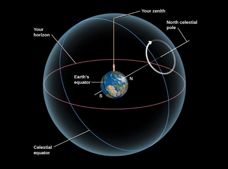
This is what we call the celestial sphere. Similarly to Earth, we can define both the celestial poles and the celestial equator. As for the radius of the celestial sphere, we consider it to be infinite, but it is required as a reference point for angles based on our zenith. With all of this in mind, we can now see how to implement this mathematical approach into a digital design.
Hardware/Software Tradeoffs
One thing that is important to keep in mind is the general complexity of this project. There are many extremely advanced designs that utilize statistical approaches with error calculations to consistently ensure alignment.
Our system was originally designed to be as simple as possible, ensuring functionality and alignment for much shorter time periods than a typical astronomical image requires. For example, there are some commercially available products, such as arcsec's Saggita startracker, that have extremely high precision (2 arcseconds) and are specialized for harsh space weather conditions. However, these types of devices have been designed by a team of specialized engineers over a long period of time, making an implementation of accurate star tracking software far beyond our scope.
Another important thing to note here is that the concept of "star tracking" isn't what's being copyrighted or patented. Instead, it's the specific algorithms that are used at the industry level. For example, most notably would be Raytheon's patent #12442642, "Star trackers for range determination in rendezvous and proximity operations", which details information on a new system using two star trackers for high precision operations at close proximity in orbit.
3. Program/Hardware Design
Magnetometer
The magnetometer calibration was a critical step in ensuring the accuracy of our star tracking system, this was particularly important because we used the sensor in multiple environments such as my apartment, duffield atrium and the lab.
The raw readings from the magnetometer are affected by both hard iron offsets, caused by permanent magnetic materials near the sensor, and soft iron effects caused by ferromagnetic materials that distort magnetic fields such as our phones, lab speakers, screws etc.
Initially, we manually rotated the sensor through all orientations in each environment, collected raw X, Y, and Z readings, and applied corrections to compensate for these effects. To remove the hard iron offsets, we calculated the center of the measurement ellipses and subtracted it from all readings, while for soft iron offsets, we corrected them by applying scaling factors to normalize the axis.
This process was time consuming and manually tiring as we had to do this every testing session. We decided to write a python calibration script that automated these steps by having us just rotate the sensor once while logging data, compute the necessary hard and soft iron corrections and apply them in real time.
GPS
The next device that was required to set up was the Adafruit Ultimate GPS v3 breakout board, hosting an on-chip antenna and the actual PA1616S GPS module. Communication with this device for our purposes required a unidirectional UART connection. At no point would the pico need to send data to the GPS, therefore only requiring the Tx (GPS) to Rx (Pico), and of course power and ground.
The next step would be to decode, or parse, the information being sent through the UART channel to the pico as usable data for certain calculations as mentioned in the mathematics. In order to do this, we must first understand the format of the raw data being presented to the MCU.
The National Marine Electronics Association, or NMEA, has a standard for GPS data, namely, NMEA-0183. The basic structure of this format revolves around NMEA sentences, at maximum 82 characters, with specific tags and delimiters, as seen in Table 1.
| ASCII | Hex | Dec | Use |
|---|---|---|---|
| <CR> | 0x0d | 13 | Carriage return |
| <LF> | 0x0a | 10 | Line feed, end delimiter |
| ! | 0x21 | 33 | Start of encapsulation sentence delimiter |
| $ | 0x24 | 36 | Start delimiter |
| * | 0x2a | 42 | Checksum delimiter |
| , | 0x2c | 44 | Field delimiter |
| \ | 0x5c | 92 | TAG block delimiter |
| ^ | 0x5e | 94 | Code delimiter for HEX representation of ISO/IEC 8859-1 (ASCII) characters |
| ~ | 0x7e | 126 | Reserved |
Having a standardized format makes string parsing much easier. Luckily, only one type of NMEA sentence was required for purposes of this design, tagged “$GPGGA”, signifying that this sentence will be a GPS Fix sentence, meaning that it includes UTC, latitude, and longitude. This is exactly what is needed in order to find our zenith and allow for the program to work anywhere on the surface of the earth.
This all did not go without its struggles, however. String parsing in C is such a challenge because of the versatility of strings and how C allocates memory for them. Ensuring the correct char pointers were being accessed between dependencies was incredibly challenging, so in the end, the GPS software was all written in the main file tracker.c.
Stepper Drivers
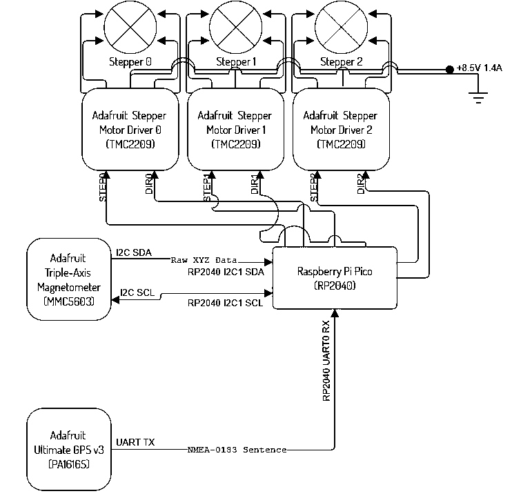
The last, and probably most important component of this device was the TMC2209 Stepper Driver. Without this, we would not be able to accurately control the rotation of each motor. Though it does allow for a UART connection, 3 stepper drivers and a gps would need 4 isolated UART channels, which is only possible on the RP2040 through means of a PIO program to simulate the protocol using software on any other GPIO.
The way around this was to manually control the driver by its STEP and DIR pins. For example, when a pulse (rising edge) is sent to the driver into the STEP pin, it will step the motor once, in our case 1.8 degrees. DIR is automatically LOW, so when set HIGH, will reverse the direction of the step. With just these two connections on each driver, we can now allocate enough GPIOs from the Pico to be able to communicate with all other peripheral devices.
HOW DOES THIS ALL COME TOGETHER?
As seen below, the RP2040 uses the GPS positioning data to get our zenith and celestial poles. Originally, the idea was to align with magnetic north and then find Polaris based on the position obtained from the GPS, which is also celestial north.
Once the device is pointing straight towards celestial north, it would just need to rotate about the celestial north axis. From here, we’d only need one stepper to control the rotation at 15.041 degrees per hour to perfectly compensate for the rotation of the Earth.
Hardware implementation
The hardware of our star tracker would allow anyone to easily replicate our project. The entire structure of our 3-axis gimbal was 3D printed from basic materials such as PLA and PETG. We used heat set inserts and socket head bolts to fasten the parts together, aluminum rod to connect the hinges, and threaded rod to connect to the motor output shafts.
For the electrical side of the hardware, we used commonly used stepper motors, stepper motor drivers (TMC2209), a GPS module (PA1616S), a magnetometer (MMC5603), and the Raspberry Pi Pico, which are all also easy for anyone to acquire.
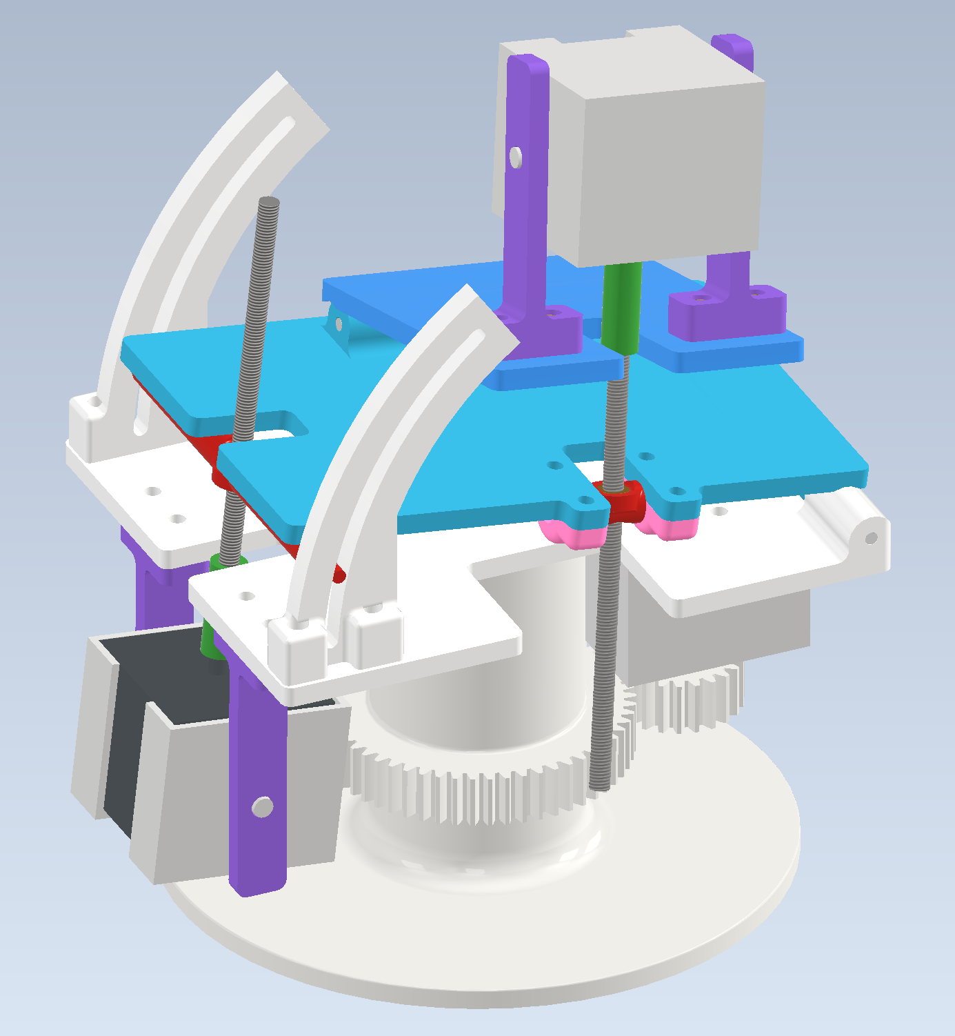
The hardware design took quite a lot of time to complete, due to the complexity of successfully implementing motion constraints in CAD. However taking the time to ensure everything moved together properly in CAD without interference meant that almost everything fit together perfectly on the first try. The one exception was that the electrical connector protruding from the motor meant that we had to modify the design to allow the motors to slide into the motor holders. Here, extensive prior experience with design for 3D printing and manufacturing was very beneficial since we had a good intuition about what tolerances to add between moving parts in the assembly.
One fundamental issue with the original design that we discovered in CAD was with the original plan to have both stepper motors below their respective plates. When making the CAD, it soon became clear that the y-axis stepper motor would have interfered with the assembly below as the plates rotate. This issue was easily resolved by inverting the y-axis stepper motor assembly and having the motor above.
Mechanical Design
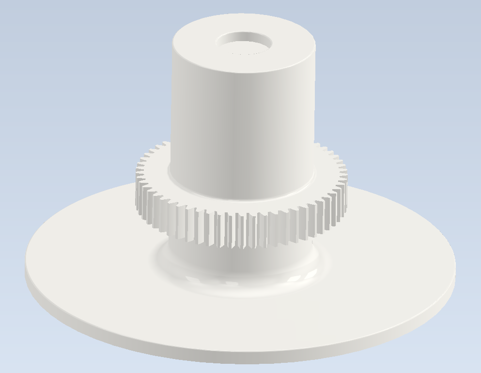
The mechanical design of our 3-axis gimbal uses one stepper motor to control each axis of rotation. First, the base has a wide platform to remain stable on the ground, a gear for the z-axis rotation around halfway up its shaft, and a small circular indentation where a pin from the plate above rests. The interface between the pin and socket was surprisingly frictionless despite us not having a bearing or adding any lubrication to the area. This allowed smooth rotation, but given more time and resources this would easily be replaced with a bearing.
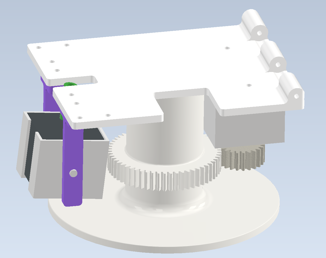
Next, the base plate has a pin on bottom to sit on the base, a stepper motor pointing down with a gear on its output shaft, a hinge for the next plate to connect to, and an arch that guides the movement for the x-axis rotation. The design of these two arches on the base plate took slight inspiration from the “OG star tracker” YouTube channel’s design of their “OG star tracker V2”. The motor to control the x-axis rotation hangs from this plate, and a threaded rod connected through its output shaft converts its rotational motion into linear motion that lifts the x-axis plate. The rotational motion is converted into linear motion as the threaded rod rotates through a heat set insert in a 3D printed rod that slides through the two arches.
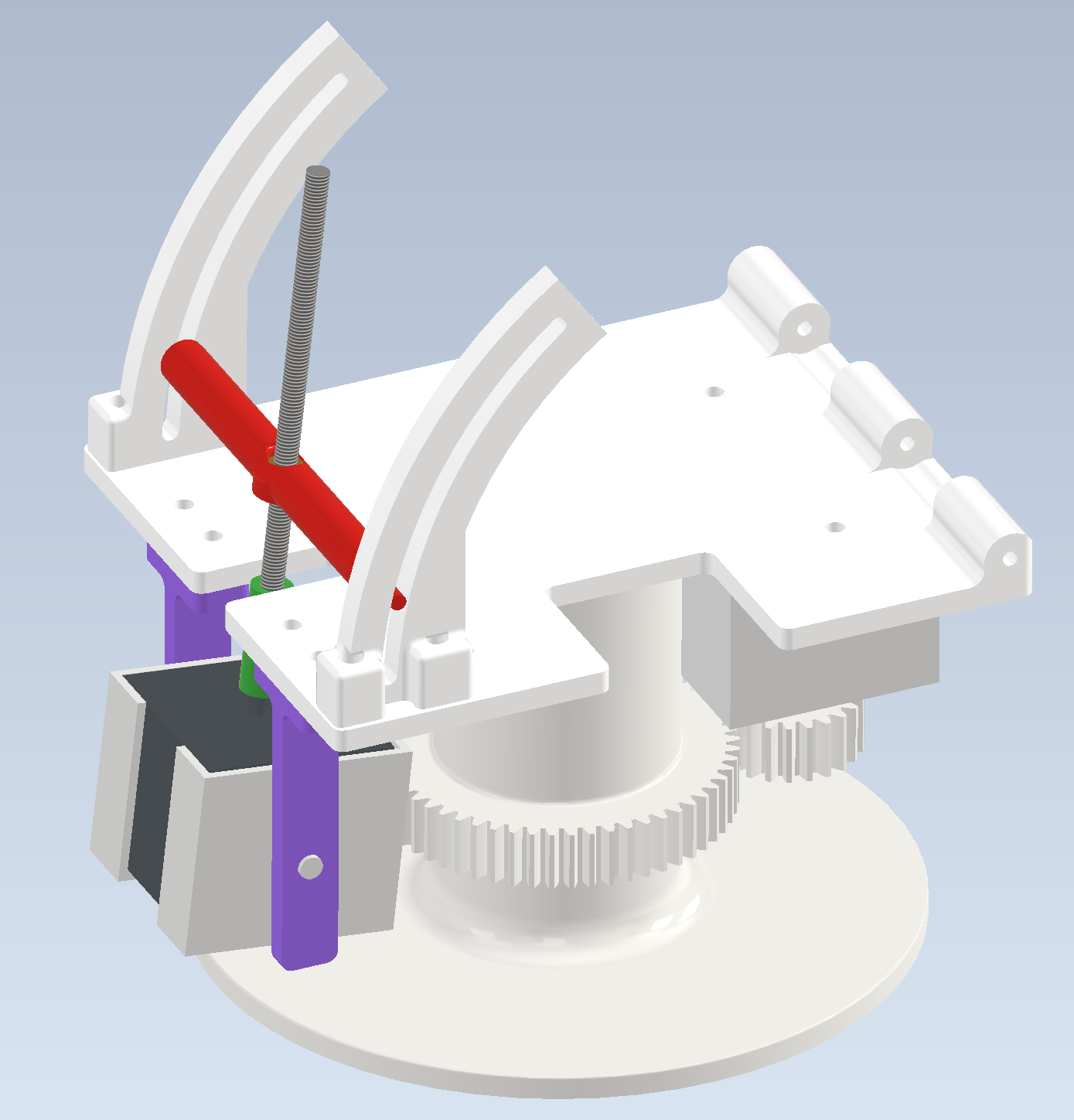
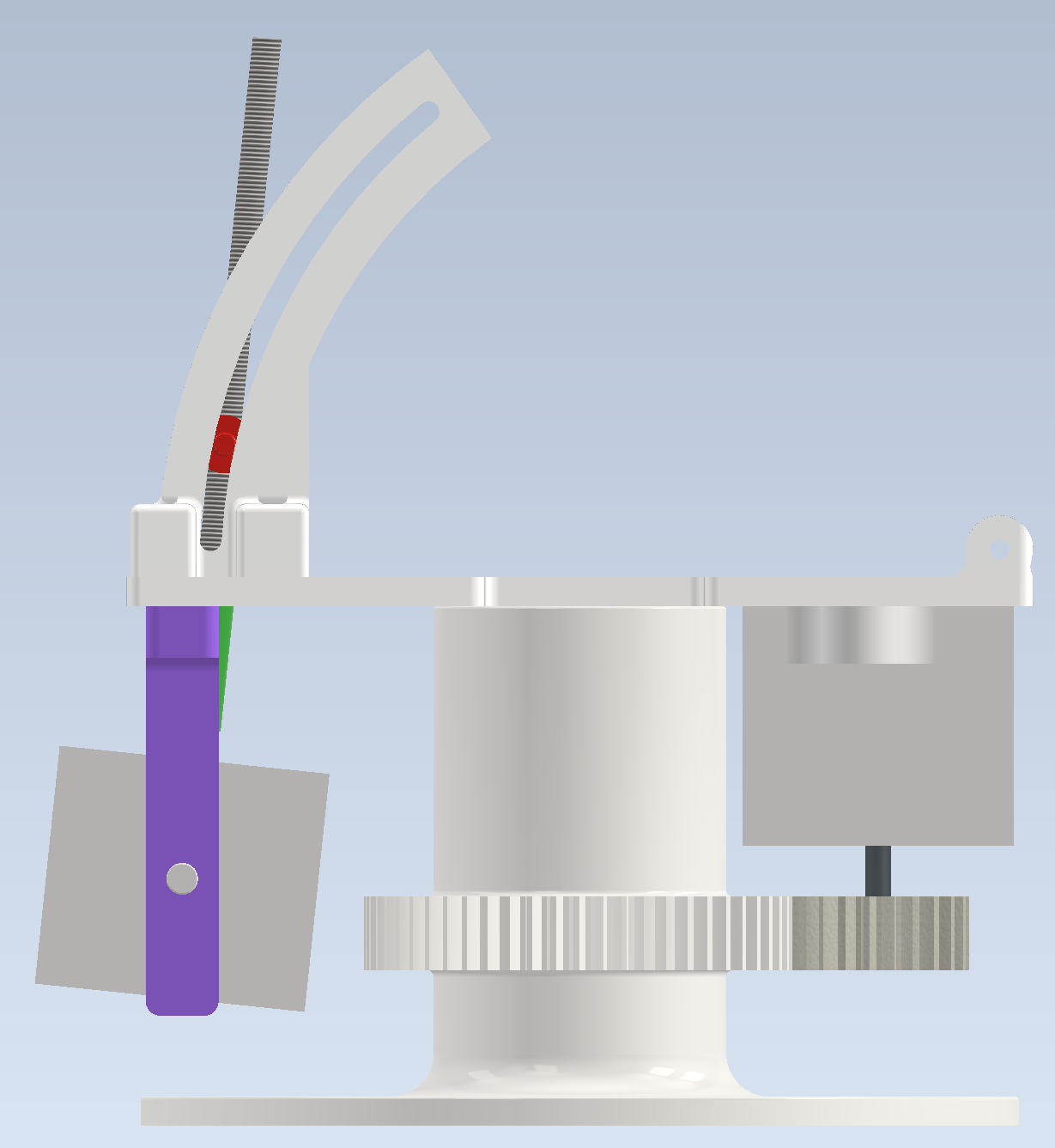
The next plate, the x-axis plate, has a hinge on the bottom to interface with the base plate which allows this plate to rotate up and down as the x-axis motor is turned. Connected to the bottom of the plate, two small arches secure a 3D printed rod with a heat set insert that reacts with the threaded rod for the y-axis rotation. The design of this arch is arguably better than the design of the arches for the x-axis rotation and given more time to iterate, we would use this connection for both the x and y rotation. Then a hinge on the top side connects with the y-axis plate.
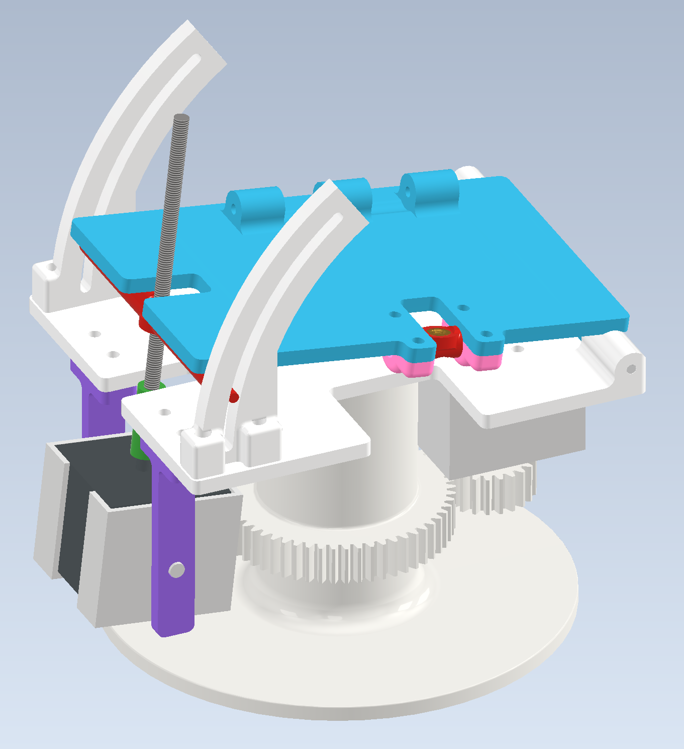
Finally, the y-axis plate has a hinge on the bottom to interface with the x-axis plate. The stepper motor to control the y-axis rotation is stood off above this plate with two arms that allow the motor to rotate in place as the angle of the plates relative to each other change. The camera mount of choice is then connected to the top of this plate so that the camera sees the benefit of all three rotational axes. Due to our rush to finish assembly for our final presentation, we ended up gluing one of our old motor mounts to the y-axis plate to hold a GoPro taking a timelapse.
In summary, the x and y axes each use a stepper motor with a threaded rod to react through a heat set insert to convert the rotational motion from the motors into linear motion to rotate their plates and the z-axis uses a gear on the third stepper motor to rotate the entire assembly around the base.
In order to split our design and testing into stages, we first designed our gimbal to only have rotation around the x and y axes. This allowed us to integrate the motors and circuitry with the mechanical assembly and test the motor control while we finished designing the base and gears for rotation around the z-axis. During this testing stage, we noticed that the motors were getting pulled slightly out from their holders which meant we would not have precise or accurate control. As a result, we modified the motor holder design slightly so that the motors could be screwed into the motor holders. Once the new base with the z-axis rotation gears and new motor holders were done being printed, we disassembled the gimbal and reassembled with the new components.
AI USE STATEMENT
For information about how we used AI during this project, please see our AI Use Statement.
5. Conclusions
Something we didn’t know at the beginning was that we’d only end up needing two motors for the entire system instead of three, but with the final design including 3 degrees of freedom, there is much more elbow room to repurpose the same device as a generic 3 axis electrically controlled gimbal.
This resulted in an overcomplication of the project that really slowed us down trying to include the third axis on an already robust device. The lesson learned here is that it is very important to have a good idea of the exact physical workings of the device before buying anything. This added level of complexity made other parts of the project more difficult. For example, if we didn’t have to include the third axis, mounting of the electronics would have been substantially simpler, and there wouldn’t have been a need to devise a solution during the final hours of our available time.
As for a comparison on our device versus commercially available products, there is still a long way to go. As previously mentioned, advanced star tracking systems are extremely complex, even using computer vision and databases to identify star patterns in the sky in order to correct for any minute errors that are accumulated over time.
Final Comments
- All code was written originally by our group, except for the standard C libraries and the Pico SDK
- No legal issues involving patents, trademarks, or copywrites, or NDAs
- Our project would not be eligible for a patent because of the relative simplicity it represents compared to the larger scale industry giants. (This idea is not original)
6. Appendices
"The group approves this report for inclusion on the course website."
"The group approves the video for inclusion on the course youtube channel."
7A. Commented C code
View our complete code listings: Code Listings Page
7B. Schematics
7C. Tasks by each team member
Jeremy designed the entirety of the mechanical structure in CAD, 3D printed all the components, cut the hinge and threaded rods, and assembled the components.
Dani took on the task of writing the GPS and stepper driver code, physical circuit design and build.
Tony took on the task of writing the magnetometer code and final integration of all components to work together.
We all communicated our progress throughout the project and worked together for the final integration of the protoboard and wiring to the motors.
8. References
- Stepper motor datasheet
- Our mechanical design took slight inspiration from the "OG star tracker" design on YouTube, specifically with the design of the arches used for the x-axis rotation
- Celestial Sphere reference
- NMEA 0183 (Table 1)