Table of Contents
- Sound Bite - One-sentence pitch of the project.
- Summary - What we built and what it does.
- High-Level Design - Architecture, rationale, math, tradeoffs.
- Hardware - Components, wiring, power, build process.
- Software - Software structure, parsing, UI, FSMs.
- IP - IP considerations.
- Parts - Bill of materials; estimated cost.
- Results - Scope traces, accuracy, performance, usability.
- Demo - Demo video, recorded by Hunter Adams.
- Conclusion - Outcomes and future improvements.
- Appendix A - Permissions for publishing and video.
- Appendix B - Hardware photos and pin diagrams.
- Appendix C - Static UI draw functions listing.
- Appendix D - Task breakdown by team member.
- References - References.
Sound Bite
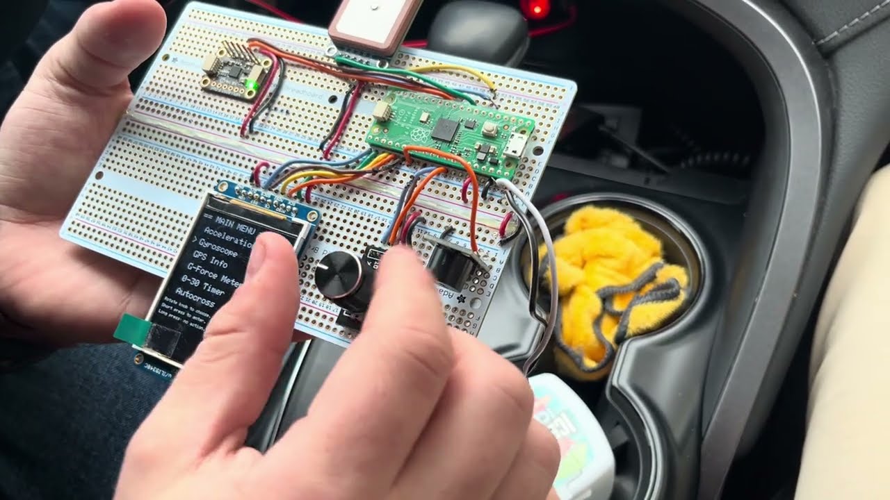
A plug and play device that can take your Auto-Cross racing experience to the next level.
Summary
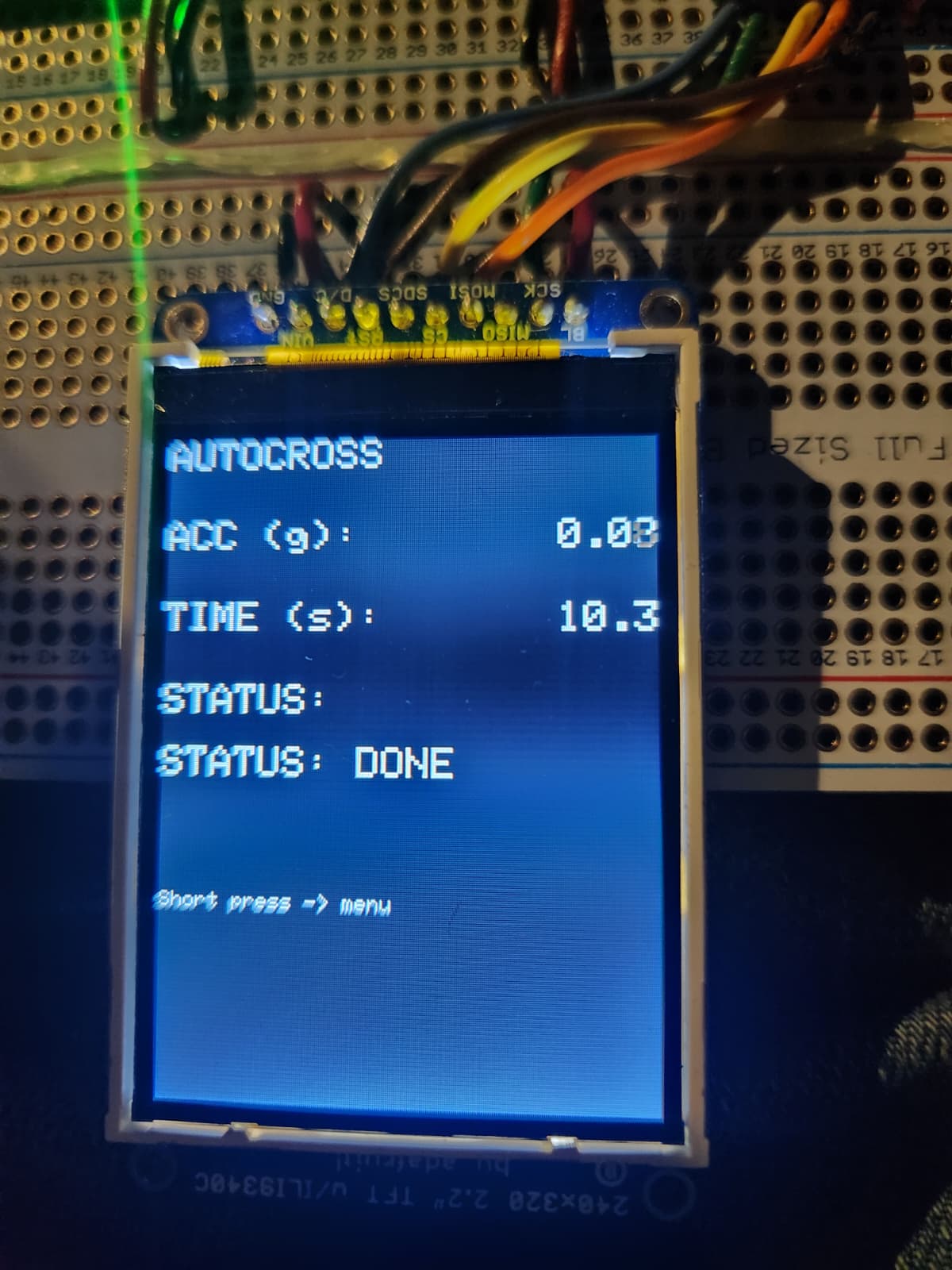
In this project we designed a device that can be plugged directly into the car. The system provides multiple important vitals to help aid your racing experience. The data collected is from a 6-DoF IMU which provides acceleration and gyroscope data. This constitutes the real-time G-Force meter that can help push your car to the limits. The project also includes a Neo-7M GPS chip with an active antenna for increased reception. This module adds to the device, allowing the driver to attain accurate 0-60mph (or 0-30) times. The acceleration and speed are used to create a function called “AutoCross” that measures time for autocross runs and automatically stops when the time-trial is complete.
High-Level Design
Rationale and Sources of Project Idea
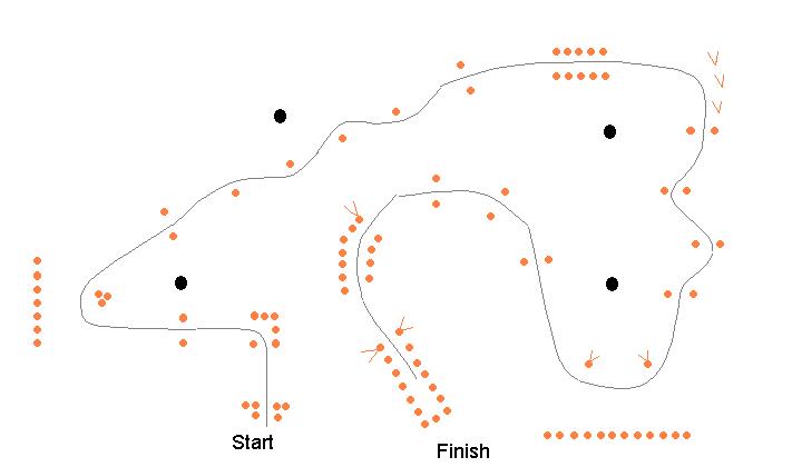
One of the main inspirations for this project was the love of motorsports and cars that we both share. Andranik had gone to multiple Auto-Cross events in the Upstate New-York region and noticed the difficulty in tracking and improving on time-trial events. This led us to the idea of creating a racing-aid device that can plug into a car and get useful information for drivers. This can help drivers improve their times and understand their cars and driving in a quantitative manner.
Background Math
Some math was required in the scaling and creating of the G-Force meter. This included a thorough understanding of reference frames for the IMU module and the car in order to produce coherent data. There was also some easy math done to remove the bias from the “AutoCross” setting which simply demanded systematic subtraction of the settling time. There was also some math done to ensure a nice GUI system fit on our TFT screen.
Logical Structure
The logical structure of the device is quite simple. We have the central Microcontroller which branches out to our 3 peripherals: the IMU, the TFT screen, the GPS module with the active antenna. The IMU and GPS module send raw data to the microcontroller which completes a set of instructions and calculations which are then sent to be displayed on the screen.
Hardware/Software Tradeoffs
Our biggest hardware/software tradeoff was deciding which tasks should be handled by dedicated peripherals and which should be handled in software on the RP2040. We chose a discrete TFT module with a PIO-based driver (TFTMaster) to keep hardware simple and low-cost. This change required more careful software-side rendering patterns (static redraw + incremental patch updates) to avoid flicker and keep the UI responsive. We also used a rotary encoder and button instead of a touchscreen to reduce hardware complexity and cost. This came at the cost of more complexity in software via quadrature decoding, debouncing, and UI state machines.
Another key tradeoff was timing and concurrency. We implemented the system as a single polling loop (IMU read/filter, GPS UART buffering/parsing, knob decode, UI updates) with only PPS handled by interrupt. This approach simplified software integration/debugging and avoided multi-thread timing bugs, but it also meant some operations (like buzzer countdown beeps using sleep_ms()) are blocking. For our use case this was deemed acceptable because the beeps are short and occur during a user-visible countdown, but in later iterations we would likely move buzzer timing to a non-blocking state machine or use timer alarm callbacks.
Finally, we balanced accuracy versus implementation complexity. For IMU-derived visuals (G-Force meter), we prioritized stability and readability on the TFT by applying a simple first-order low-pass filter in software, rather than implementing more complex features that would require more tuning and more computation. For GPS, we relied on the module’s NMEA output (1 Hz) rather than increasing the update rate. This would again likely be changed if we had more time, or in future iterations. These choices kept hardware plug-and-play and minimized wiring, at the cost of slower speed refresh compared to vehicle bus data. In summary, we made decisions to best keep the device low-power, portable, and easy to integrate, while still achieving the intended demo performance.
Hardware Spec/Process
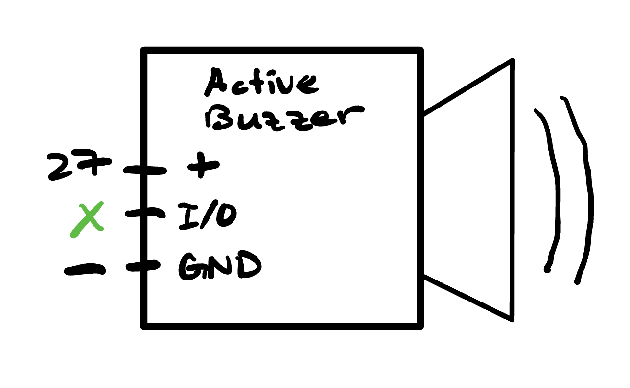
The hardware utilized for this project was reverse engineered from the features we wanted our device to implement. We drew from our experience working with the MPU 6050 IMU in lab 3 of the course. We also drew inspiration from the dashboard of many top-end racing vehicles like the Porsche 911 which contains an in-built g-force meter on a circular axis similar to ours. The code implementation of the g-force meter is in the Commented Code sections, but in terms of hardware we knew that this feature could be implemented with just the IMU. Next when working on the AutoCross function, which uses the IMU, we had the idea to use a lower bound to predict that the vehicle had finished the racing course. However; when thinking about the start of the AutoCross function, we wanted to allow the driver to focus on the car and not have to look at the display count-down. For this reason, we added a simple active buzzer which produced a short sound on 3,2,1 and then a longer sound to signal “Go!” This allows the driver to focus on the road and start immediately after the long buzzer. The hardware of the long buzzer was quite simple to implement, as it was low power, we simply connected it to GPIO 21 (Physical pin 27) and the pin was able to supply enough power to sound the buzzer.
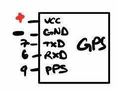
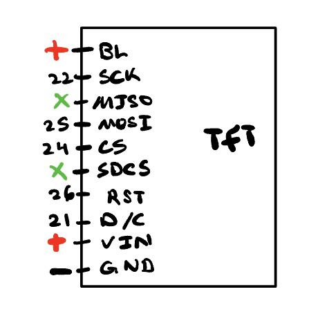
We wanted a low power option of displaying all of the data and performance metrics, and under the guidance of Hunter Adams, we decided to use a 2.2” TFT display. The physical pin wiring schematic can be found in Appendix B below. The GPS chip was the next main component we added to our device. The actual wiring of the chip was quite simple and we made sure to utilize a ship that could run on 3.3V. This allowed us to power the chip directly from the RP2040. The data being communicated between the GPS chip and the RP 2040 was done through the UART protocol. This implied that from a hardware perspective, the TX of the GPS chip is connected to the UART RX1 of the RP 2040 (physical pin 7). Then the RX of the GPS chip is connected to the UART TX1 (physical pin 6). The main issue with the GPS antenna with passive antennas is that they are very difficult to fix to satellites. It was only after a trip to the Hartung-Boothroyd Observatory that (about 15 minutes outside of Ithaca) we were able to attain an initial fix. After this point the GPS had a “hot start” and was able to fix satellites in about 15 seconds when placed in the car. We then further improved by ordering a simple active antenna which was magnetic and allowed us to keep the device on the dash and the active antenna clinged to the roof. This led to an even faster fix and more confidence when driving through more crowded areas outside.
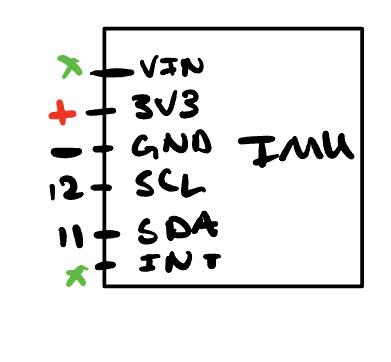
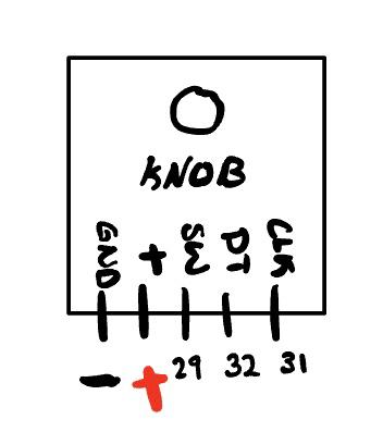
The wiring of the IMU was done in a similar fashion to lab 3 of this course and the physical pin wiring diagram can be seen in the schematic appendix below. Since we are not planning on using the serial communication with the deconder, we need some way to navigate the GUI. This is where we decided to use a knob (rotary encoder) with a button to allow for a simple yet effective way of interacting with the device. Once again, the physical pin wiring diagram is in the appendix below.
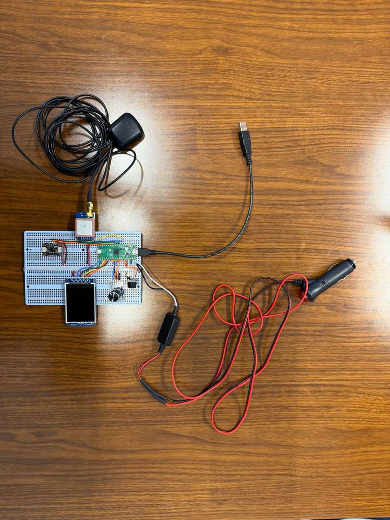
Next, a short discussion of the power dynamics is appropriate. As mentioned above, we wanted to maximize the usability of this device across all types of cars. The reliable power source found in almost all cars produced in the last 60 years is the 12V cigarette lighter. We first found a plug in adapter that you can plug in the 12V adapter, with a simple On/Off switch the yields two wires, a positive +12V and ground. These wires were then soldered and heat shrunk directly into the input of a DC/DC converter which outputs 3.3V see [Figure 5]. The output of the DC/DC converter which was confirmed to be around 3.3V was fed into the VSYS pin (physical pin 39) By reading through the data sheets of the various components we used, we made sure to only use components that needed 3.3V. This allowed for the creation of one large power, and ground rail. The 3V3OUT pin (physical pin 36) of the RP 2040 was connected to main power rail running down both universal PCBs. This allowed for simple connections to be made between the modules and the main power rail. The GND pin (physical pin 38) was also connected to the main GND of the system and shorted across the two universal PCBs and allowed for easy GND connections to each peripheral.
Finally, Appendix B contains an image of our “in process” circuit which we built on a standard breadboard with standard plug in wires. This led to a very crowded working environment which was difficult to work with. We also noticed that the screen would flicker significantly and we had a fear that placing it in the car could have detrimental effects. Thus to increase the build quality we switched to a universal PCB and soldered all of the connections. This completely solved the flickering TFT screen issue and led to a much cleaner design. Moving forward it could have been helpful to create a little enclosure which would just have the knob and screen, leading to a more product-like feel.
Software Spec/Process
We would first like to thank Parth Sharma [1] for their documentation on PIO-based TFT drivers (TFTMaster). It is included in the student-generated documentation on 4760 Webpage [2].
TFTMaster Library Functions Used
Below is every TFTMaster function this project calls, along with what it does in the UI.
-
tft_init_hw()
Initializes the Pico’s interface for the TFT. -
tft_begin()
Initializes display controller and puts TFT into a usable state (init sequence). -
tft_setRotation(uint8_t rot)
Sets screen rotation, changing how(x, y)coordinates map. -
tft_fillScreen(uint16_t color)
Fills the full screen with a color (clears display) -
tft_setTextColor2(uint16_t fg, uint16_t bg)
Sets text foreground/background colors. -
tft_setTextSize(uint8_t size)
Sets the text scale factor for headings/readouts. -
tft_setCursor(int16_t x, int16_t y)
Moves the text cursor to a pixel location (generally used before writing text). -
tft_writeString(const char *s)
Writes a C string at current cursor position using current font size and colors. -
tft_drawCircle(int16_t x, int16_t y, int16_t r, uint16_t color)
Draws outline circle (used for G-Force meter rings). -
tft_drawLine(int16_t x0, int16_t y0, int16_t x1, int16_t y1, uint16_t color)
Draws a line between two points (used for G-Force meter crosshair). -
tft_fillCircle(int16_t x, int16_t y, int16_t r, uint16_t color)
Draws a filled circle (used for moving dot in G-Force meter and for erasing previous dot).
We note that we also use color constants such as
ILI9340_BLACK, ILI9340_WHITE, which are predefined in the display driver headers in TFTMaster. Note also that
the one-time UI layout “draw” functions (e.g., draw_menu_screen(), draw_gps_screen(), etc.)
are listed in Appendix C.
GPS Coordinate Parsing & Timing (NMEA via UART1)
The GPS module streams NMEA sentences over UART1 at 9600 baud. Our firmware buffers each line, verifies its checksum, then extracts latitude/longitude (RMC or GGA) plus UTC time and speed (RMC). We used the following video [3] as a tutorial for implementing our GPS module:
- Sentence buffering: read complete NMEA lines from UART into
nmea_buf. - Integrity: verify XOR checksum (
$...*HH) before parsing. - Parsing helpers: split fields by comma, convert degree-minutes to decimal degrees.
- Outputs: update
gps_lat,gps_lon,gps_hh/mm/ss, andgps_spd_knots. - PPS: interrupt-based pulse-per-second lock indicator (
PPS: LOCKED).
nmea_checksum_ok() - Verifies NMEA sentence integrity using XOR checksum. Computes XOR of all characters between $ and * delimiters and compares the result to the hexadecimal checksum at the end of the sentence. Invalid formatting or missing fields cause rejection. Prevents corrupted UART data from being parsed.
// XOR checksum check for NMEA lines like: $GPRMC,...*hh
static bool nmea_checksum_ok(const char *s)
{
	if (!s || s[0] != '$')
		return false;
	const char *star = strchr(s, '*');
	if (!star)
		return false;

	uint8_t cs = 0;
	for (const char *p = s + 1; p < star; p++)
		cs ^= (uint8_t)(*p);

	if (strlen(star) < 3)
		return false;
	uint8_t got = (uint8_t)strtoul(star + 1, NULL, 16);
	return cs == got;
}
nmea_field() - Locates the start of a comma-separated field within an NMEA sentence. Scans the string, counts commas, and returns pointer to requested field without modifying the buffer. If the field does not exist, returns NULL.
// Return pointer to nth comma-separated field (0-based)
static const char *nmea_field(const char *sentence, int field_num)
{
	int commas = 0;
	const char *p = sentence;
	if (field_num == 0)
		return p;
	while (*p)
	{
		if (*p == ',')
		{
			commas++;
			if (commas == field_num)
				return p + 1;
		}
		p++;
	}
	return NULL;
}
nmea_degmin_to_decdeg() - converts ddmm.mmmm/dddmm.mmmm to signed decimal degrees.
// Convert ddmm.mmmm (lat) or dddmm.mmmm (lon) to decimal degrees
static float nmea_degmin_to_decdeg(const char *s, char hemi, bool is_lat)
{
	if (!s || !s[0])
		return 0.0f;

	int deg_digits = is_lat ? 2 : 3;
	if ((int)strlen(s) < deg_digits + 2)
		return 0.0f;

	char deg_str[4] = {0};
	for (int i = 0; i < deg_digits; i++)
		deg_str[i] = s[i];

	float deg = (float)atoi(deg_str);
	float minutes = (float)atof(s + deg_digits);

	float decdeg = deg + minutes / 60.0f;
	if (hemi == 'S' || hemi == 'W')
		decdeg = -decdeg;
	return decdeg;
}
nmea_parse_latlon() - parses latitude/longitude from RMC or GGA (after checksum verification).
// Parse lat/lon from RMC or GGA
static bool nmea_parse_latlon(const char *sentence, float *lat, float *lon)
{
	if (!sentence || sentence[0] != '$')
		return false;
	if (!nmea_checksum_ok(sentence))
		return false;

	// RMC
	if (strncmp(sentence, "$GPRMC", 6) == 0 || strncmp(sentence, "$GNRMC", 6) == 0)
	{
		const char *status = nmea_field(sentence, 2);
		if (!status)
			return false;

		const char *lat_s = nmea_field(sentence, 3);
		const char *lat_h = nmea_field(sentence, 4);
		const char *lon_s = nmea_field(sentence, 5);
		const char *lon_h = nmea_field(sentence, 6);

		if (!lat_s || !lon_s || !lat_h || !lon_h)
			return false;
		if (!lat_s[0] || !lon_s[0])
			return false;

		char lh = lat_h[0];
		char loh = lon_h[0];
		if (!(lh == 'N' || lh == 'S'))
			return false;
		if (!(loh == 'E' || loh == 'W'))
			return false;

		float la = nmea_degmin_to_decdeg(lat_s, lh, true);
		float lo = nmea_degmin_to_decdeg(lon_s, loh, false);

		if (la < -90.0f || la > 90.0f)
			return false;
		if (lo < -180.0f || lo > 180.0f)
			return false;

		*lat = la;
		*lon = lo;
		return true;
	}

	// GGA
	if (strncmp(sentence, "$GPGGA", 6) == 0 || strncmp(sentence, "$GNGGA", 6) == 0)
	{
		const char *lat_s = nmea_field(sentence, 2);
		const char *lat_h = nmea_field(sentence, 3);
		const char *lon_s = nmea_field(sentence, 4);
		const char *lon_h = nmea_field(sentence, 5);
		const char *fix_q = nmea_field(sentence, 6);

		if (!lat_s || !lon_s || !lat_h || !lon_h || !fix_q)
			return false;
		if (!lat_s[0] || !lon_s[0])
			return false;

		char lh = lat_h[0];
		char loh = lon_h[0];
		if (!(lh == 'N' || lh == 'S'))
			return false;
		if (!(loh == 'E' || loh == 'W'))
			return false;

		float la = nmea_degmin_to_decdeg(lat_s, lh, true);
		float lo = nmea_degmin_to_decdeg(lon_s, loh, false);

		if (la < -90.0f || la > 90.0f)
			return false;
		if (lo < -180.0f || lo > 180.0f)
			return false;

		*lat = la;
		*lon = lo;
		return true;
	}

	return false;
}
nmea_parse_time_speed() - extracts UTC time (RMC/GGA) and speed in knots (RMC only).
// Parse UTC time + speed from RMC (and time from GGA)
static bool nmea_parse_time_speed(const char *sentence, int *hh, int *mm, int *ss, float *speed_knots)
{
	if (!sentence || sentence[0] != '$')
		return false;
	if (!nmea_checksum_ok(sentence))
		return false;

	bool is_rmc = (strncmp(sentence, "$GPRMC", 6) == 0 ||
				   strncmp(sentence, "$GNRMC", 6) == 0);
	bool is_gga = (strncmp(sentence, "$GPGGA", 6) == 0 ||
				   strncmp(sentence, "$GNGGA", 6) == 0);

	// Only handle RMC or GGA for time/speed
	if (!is_rmc && !is_gga)
		return false;

	const char *time_s = nmea_field(sentence, 1);
	if (!time_s || (int)strlen(time_s) < 6)
		return false;

	char h_str[3] = {time_s[0], time_s[1], 0};
	char m_str[3] = {time_s[2], time_s[3], 0};
	char s_str[3] = {time_s[4], time_s[5], 0};

	*hh = atoi(h_str);
	*mm = atoi(m_str);
	*ss = atoi(s_str);

	float spd = 0.0f;
	if (is_rmc)
	{
		const char *spd_s = nmea_field(sentence, 7);
		if (spd_s && spd_s[0])
			spd = (float)atof(spd_s);
	}
	*speed_knots = spd;
	return true;
}
gps_read_sentence() - Reads raw bytes from the GPS UART and creates NMEA sentence. Characters are appended to a buffer until a \n is received, then the string is null-terminated and marked ready. \r is ignored, and overly long sentences are discarded by resetting the buffer index.
// Read bytes from UART into a line buffer; true when '\n' ends a sentence
static bool gps_read_sentence(void)
{
	while (uart_is_readable(GPS_UART_ID))
	{
		char c = uart_getc(GPS_UART_ID);
		if (c == '\r')
			continue;

		if (c == '\n')
		{
			nmea_buf[nmea_idx] = 0;
			nmea_idx = 0;
			return true;
		}

		if (nmea_idx < (int)(sizeof(nmea_buf) - 1))
		{
			nmea_buf[nmea_idx++] = c;
		}
		else
		{
			nmea_idx = 0;
		}
	}
	return false;
}
gps_pps_irq() - PPS interrupt callback to track lock/recency.
// PPS interrupt callback
void gps_pps_irq(uint gpio, uint32_t events)
{
	if (gpio == GPS_PPS_PIN && (events & GPIO_IRQ_EDGE_RISE))
	{
		gps_pps_count++;
		gps_last_pps_time = get_absolute_time();
	}
}
The UART interface is configured once at boot (UART1, 9600 baud, 8N1) and the GPS module is connected using
the Pico’s UART pin mux. PPS is handled with an interrupt on a dedicated GPIO, and we compute a simple “recency”
flag so we only display PPS: LOCKED when pulses have arrived in the last ~2 seconds (2000000 us).
// GPS UART1
uart_init(GPS_UART_ID, GPS_BAUD);
gpio_set_function(GPS_TX_PIN, GPIO_FUNC_UART);
gpio_set_function(GPS_RX_PIN, GPIO_FUNC_UART);
uart_set_format(GPS_UART_ID, 8, 1, UART_PARITY_NONE);
uart_set_fifo_enabled(GPS_UART_ID, true);

// PPS pin (GP6)
gpio_init(GPS_PPS_PIN);
gpio_set_dir(GPS_PPS_PIN, GPIO_IN);
gpio_set_irq_enabled_with_callback(
	GPS_PPS_PIN,
	GPIO_IRQ_EDGE_RISE,
	true,
	&gps_pps_irq);
// ---- PPS recency check (last 2 seconds) ----
bool pps_recent = false;
if (gps_pps_count > 0)
{
	int64_t dt_us = absolute_time_diff_us(gps_last_pps_time, get_absolute_time());
	if (dt_us < 2000000)
	{ // 2 seconds
		pps_recent = true;
	}
}
IMU (MPU-6050) Data Acquisition & Filtering (I2C)
The MPU-6050 provides 6-DoF inertial measurements: 3-axis acceleration and 3-axis angular velocity. We connect the sensor over I2C (same wiring strategy as Lab 3) and continuously sample it in the main loop to drive the Accel/Gyro screens and the real-time G-Force meter.
- I2C bring-up: Initialize the I2C peripheral, configure SDA/SCL pins, and enable pull-ups.
- Sensor reset: Reset the MPU-6050 at boot to ensure a known starting state.
- Raw reads: Each sample returns raw fixed-point (
fix15) accel and gyro values. - Scaling + filtering: Values are converted to floats and passed through a first-order low-pass filter.
i2c_init(), gpio_set_function(), gpio_pull_up() - Initializes I2C, configures the bus pins, allows RP2040 to communicate with the MPU-6050.
// I2C + MPU6050
	i2c_init(I2C_CHAN, I2C_BAUD_RATE);
	gpio_set_function(SDA_PIN, GPIO_FUNC_I2C);
	gpio_set_function(SCL_PIN, GPIO_FUNC_I2C);
	gpio_pull_up(SDA_PIN);
	gpio_pull_up(SCL_PIN);
mpu6050_reset() - Resets the IMU at startup. We add short delays around reset so the device has time
to reboot.
sleep_ms(100);
mpu6050_reset();
sleep_ms(100);
mpu6050_read_raw() - Reads latest accelerometer and gyroscope samples into fix15 arrays
(acceleration[3] and gyro[3]).
mpu6050_read_raw(acceleration, gyro);
for (int i = 0; i < 3; i++)
{
	accel_f[i] = fix2float15(acceleration[i]);
	gyro_f[i]  = fix2float15(gyro[i]);
}
We use fix2float15() + low-pass filter to convert fixed-point sensor output to float and smooth it: x_f = alpha*x + (1-alpha)*x_f. This reduces UI jitters and stabilizes
dot movement in G-Force meter.
const float alpha = 0.1f;

// ---- IMU read + LPF ----
mpu6050_read_raw(acceleration, gyro);
for (int i = 0; i < 3; i++)
{
	float a = fix2float15(acceleration[i]);
	float g = fix2float15(gyro[i]);

	accel_f[i] = alpha * a + (1.f - alpha) * accel_f[i];
	gyro_f[i]  = alpha * g + (1.f - alpha) * gyro_f[i];
}
We store the latest IMU measurements in both raw and filtered form. The raw IMU arrays are fixed-point values read from the sensor driver, and the filtered arrays are floats used directly for UI and computations (G-force, autocross end detection, etc.). Keeping both representations makes the read path simple and the UI path consistent.
// IMU data arrays (raw fix15)
fix15 acceleration[3];
fix15 gyro[3];

// LPF state (float)
float accel_f[3] = {0.0f, 0.0f, 0.0f};
float gyro_f[3]  = {0.0f, 0.0f, 0.0f};
FSMs
Our software uses two FSMs: (1) a button-press FSM for distinguishing short vs. long presses, and (2) the main UI/menu FSM for switching between screens. The rotary encoder rotation is continuously decoded (quadrature), while screen changes are event-driven by a short press.
Rotary Encoder Quadrature Decode (State Table)
The encoder has two signals (CLK and DT). Each sample forms a 2-bit state ((clk<<1)|dt), and each
transition from the previous state to the current state indexes into the below lookup quad_table[16]
We accumulate steps and only change knob_count once enough consistent transitions occur, which helps
reject bounce. We found that this was the (simplest) reliable way for our knob to work as intended (without double jumping on a single turn, for example).
// Quadrature transition table (prev_state<<2 | curr_state) -> step
static const int8_t quad_table[16] = {
    0, +1, -1, 0,
    -1, 0, 0, +1,
    +1, 0, 0, -1,
    0, -1, +1, 0
};
// Poll rotary encoder quadrature
void update_knob(void)
{
int clk = gpio_get(KNOB_CLK);
int dt = gpio_get(KNOB_DT);
uint8_t enc_curr_state = (clk << 1) | dt;
uint8_t index = (enc_prev_state << 2) | enc_curr_state;
int8_t step = quad_table[index];
if (step != 0)
{
enc_accum += step;
if (enc_accum <= -2)
{
if (knob_count < 10) knob_count++;
enc_accum = 0;
}
else if (enc_accum >= 2)
{
if (knob_count > 0) knob_count--;
enc_accum = 0;
}
}
enc_prev_state = enc_curr_state;
}
init_knob() - Configures the encoder’s quadrature pins and the pushbutton as inputs with pull-ups.
It also initializes the previous quadrature state so the first transition index is valid.
void init_knob(void)
{
	gpio_init(KNOB_CLK);
	gpio_set_dir(KNOB_CLK, GPIO_IN);
	gpio_pull_up(KNOB_CLK);

	gpio_init(KNOB_DT);
	gpio_set_dir(KNOB_DT, GPIO_IN);
	gpio_pull_up(KNOB_DT);

	gpio_init(KNOB_PRESS);
	gpio_set_dir(KNOB_PRESS, GPIO_IN);
	gpio_pull_up(KNOB_PRESS);

	int clk = gpio_get(KNOB_CLK);
	int dt = gpio_get(KNOB_DT);
	enc_prev_state = (clk << 1) | dt;
	enc_accum = 0;
}
Knob Button FSM (Short vs. Long Press)
The button FSM tracks three pieces of state: the previous button level (last_press),
whether a press is currently being timed (press_armed), and the timestamp of the press start
(press_t0). Presses longer than 800 ms are treated as “long press”
(we did not end up implementing a usecase for this, though we were intitially intending to).
- State:
IDLE(press_armed=false) andARMED(press_armed=true) - Transition 1: falling edge (1→0) →
ARMED, storepress_t0 - Transition 2: rising edge (0→1) →
IDLE, compute duration and set whether short/long event
bool update_knob_press_event(void)
{
	int now = gpio_get(KNOB_PRESS);

	// IDLE -> ARMED on falling edge
	if (!press_armed && last_press == 1 && now == 0)
	{
		press_armed = true;
		press_t0 = get_absolute_time();
	}

	// ARMED -> IDLE on rising edge, classify press
	if (press_armed && last_press == 0 && now == 1)
	{
		press_armed = false;

		int64_t dt_us = absolute_time_diff_us(press_t0, get_absolute_time());
		if (dt_us > 800000)
		{
			last_press = now;
			return false;
		}
		else
		{
			press_count++;
			last_press = now;
			return true;
		}
	}

	last_press = now;
	return false;
}
Main Menu / UI FSM (Screen Navigation)
The UI is an FSM stored in ui_state. While in UI_MENU, the rotary encoder
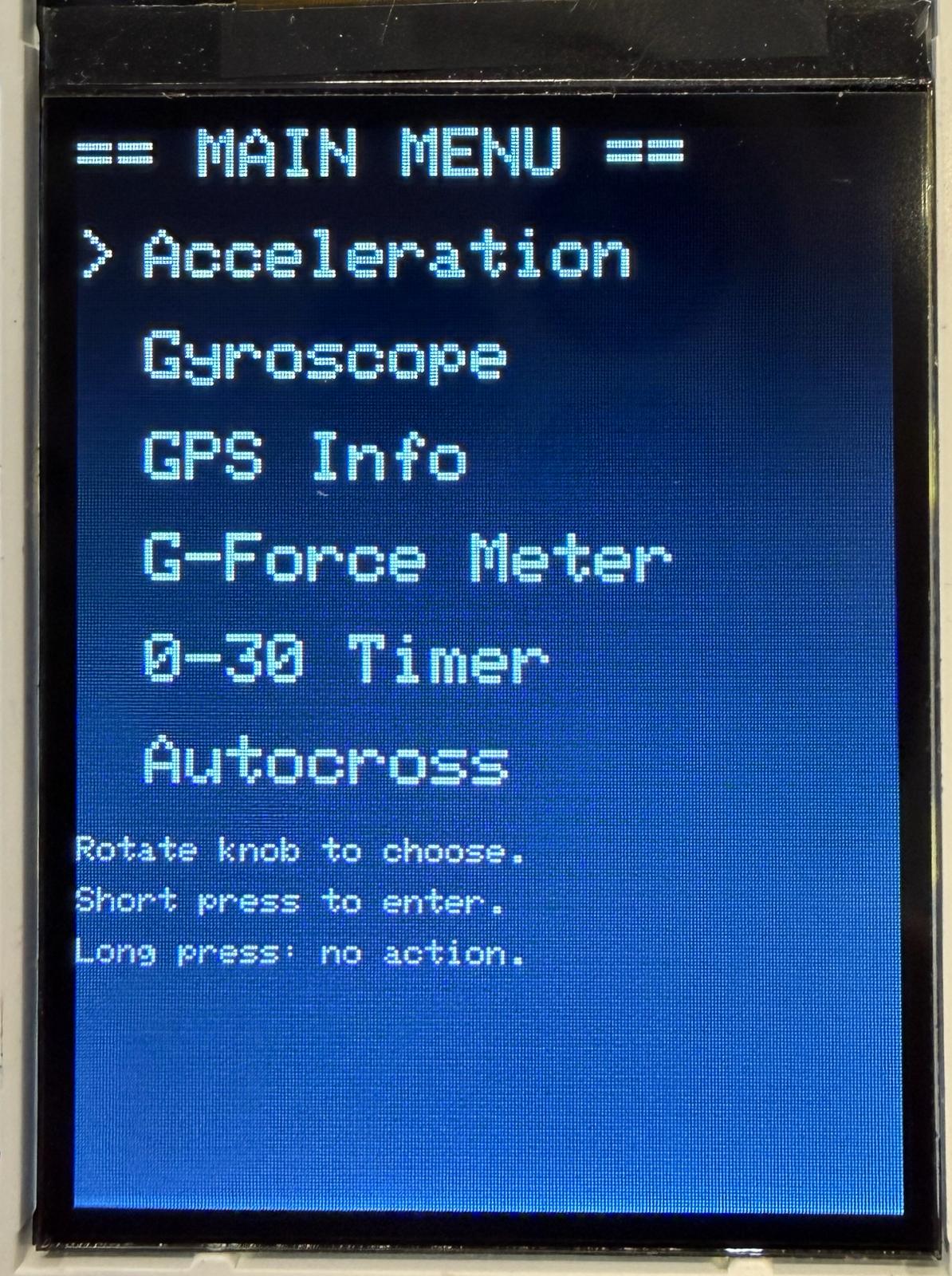
selects one of six menu items (from knob_count), and a short press transitions into the
chosen screen. From any non-menu screen, a short press returns to UI_MENU.
- States:
UI_MENU,UI_ACCEL,UI_GYRO,UI_GPS,UI_GFORCE,UI_ZEROTO60,UI_AUTOCROSS - Selection:
menu_sel = clamp(knob_count / 2, 0..5) - Enter: short press in
UI_MENU→ transition to selected mode (and reset that mode’s state) - Exit: short press in any mode →
UI_MENU(and stop/clear Autocross if leaving)
// UI FSM TRANSITIONS
if (ui_state == UI_MENU)
{
	// 6 menu items, knob_count 0..10 -> 0..5; clamp to 0..5
	int new_sel = knob_count / 2; // 0..5
	if (new_sel > 5)
		new_sel = 5;
	menu_sel = new_sel;

	if (short_press)
	{
		if (menu_sel == 0) ui_state = UI_ACCEL;
		if (menu_sel == 1) ui_state = UI_GYRO;
		if (menu_sel == 2) ui_state = UI_GPS;
		if (menu_sel == 3) ui_state = UI_GFORCE;

		if (menu_sel == 4)
		{
			ui_state = UI_ZEROTO60;
			// Reset 0-30 state machine
			zt_state = ZT_WAIT_STOP;
			zt_result_sec = 0.0f;
		}

		if (menu_sel == 5)
		{
			ui_state = UI_AUTOCROSS;
			// Reset Autocross state machine
			ac_state = AC_COUNTDOWN;
			ac_result_sec = 0.0f;
			ac_in_zero_window = false;
			ac_last_beep_step = 0;
			ac_countdown_t0 = get_absolute_time();
		}

		ui_redraw = true;
	}
}
else
{
	if (short_press)
	{
		ui_state = UI_MENU;
		ui_redraw = true;

		// Reset Autocross to idle when leaving the screen
		ac_state = AC_IDLE;
		ac_in_zero_window = false;
		gpio_put(BUZZER_PIN, 0); // make sure it's OFF
	}
}
Timer FSMs (0–60 and Autocross)
In addition to the UI navigation FSM, the project contains two mode FSMs that run while the screen is active:
the 0–30 timer (zt_state) and the Autocross timer (ac_state). Both are implemented as small
state machines that update once per main loop and use the Pico’s microsecond timestamps to compute durations.
zt_state_t - 0–30 timer states. The system waits until the vehicle is stopped, runs a 3-2-1 countdown, then times until the GPS speed reaches the target threshold.
typedef enum
{
	ZT_IDLE = 0,
	ZT_WAIT_STOP,
	ZT_COUNTDOWN,
	ZT_RUNNING,
	ZT_DONE
} zt_state_t;

static zt_state_t zt_state = ZT_IDLE;
static absolute_time_t zt_t0;
static absolute_time_t zt_countdown_t0;
static float zt_result_sec = 0.0f;

static const float ZT_STOP_THRESH_MPH = 1.0f; // consider "stopped" below this
static const float ZT_TARGET_MPH = 30.0f;     // target speed
ac_state_t - Autocross states. After a countdown, we run the timer until horizontal acceleration stays below a threshold for a fixed hold time (finish detection).
typedef enum
{
	AC_IDLE = 0,
	AC_COUNTDOWN,
	AC_RUNNING,
	AC_DONE
} ac_state_t;

static ac_state_t ac_state = AC_IDLE;
static absolute_time_t ac_t0;
static absolute_time_t ac_countdown_t0;
static absolute_time_t ac_near_zero_t0;
static bool ac_in_zero_window = false;
static float ac_result_sec = 0.0f;
static int ac_last_beep_step = 0;

static const float AC_ACCEL_TOL_G = 0.10f;  // "near-zero" horiz accel in g
static const float AC_ZERO_HOLD_SEC = 2.0f; // need this long below tol
The 0-30 timer uses GPS speed (from knots) to detect when the car is stopped and when it hits the target. The Autocross timer instead uses IMU horizontal acceleration magnitude, treating “near-zero sustained acceleration” as a finish condition.
buzzer_beep_ms(), buzzer_beep_short(), buzzer_beep_long() - Active-high buzzer helpers used during Autocross countdown and on completion.
static void buzzer_beep_ms(int duration_ms)
{
	gpio_put(BUZZER_PIN, 1); // ON
	sleep_ms(duration_ms);
	gpio_put(BUZZER_PIN, 0); // OFF
}

static void buzzer_beep_short(void)
{
	buzzer_beep_ms(120); // short beep
}

static void buzzer_beep_long(void)
{
	buzzer_beep_ms(350); // longer beep
}
The buzzer uses blocking delays (sleep_ms()) (which is acceptable here because the countdown beeps are short and the UI remains responsive enough for demonstration).
We also track the last countdown step in Auto-Cross (ac_last_beep_step) so the buzzer only fires once per transition.
We include the beep audio below.
UI Rendering Strategy & Screen Update Pattern
Our UI is structured around a screen-based state machine (ui_state) and a redraw flag
(ui_redraw). When we enter a new screen, we do one full redraw (clear the display, draw labels,
draw static geometry). While staying on the same screen, we only update the changing values (numbers,
arrows, dot position) to avoid flicker and keep the loop responsive (this was a consistent problem that we ran into, this was again the simplest fix).
- Full redraw (slow): only when the screen changes (
ui_redraw = true) - Incremental updates (fast): update only the parts that change each loop iteration
- Overwrite technique: most numeric strings include trailing spaces (e.g.,
"%7.4f ") so old digits get erased
1) Redraw-on-state-change
Every time the UI transitions to a different state (menu to GPS, GPS to menu, etc.), we set
ui_redraw = true. This clears the screen and draws all static content only one time.
After that, ui_redraw is cleared, and the program enters a more lightweight update loop for the active state.
// UI RENDERING
if (ui_redraw)
{
	ui_redraw = false;
	switch (ui_state)
	{
	case UI_MENU:
		draw_menu_screen();
		break;
	case UI_ACCEL:
		draw_accel_screen();
		break;
	case UI_GYRO:
		draw_gyro_screen();
		break;
	case UI_GPS:
		draw_gps_screen();
		break;
	case UI_GFORCE:
		draw_gforce_screen();
		break;
	case UI_ZEROTO60:
		draw_zero_to_sixty_screen();
		break;
	case UI_AUTOCROSS:
		draw_autocross_screen();
		break;
	}
}
This approach prevents full-screen clears (which cause a very noticable flicker on TFTs) and keeps the update loop fast enough to feel responsive while still being able to read sensors and handle input.
2) Menu: arrow-only incremental updates
We redraw the menu screen once (title + all entries),
then only update the selection arrow when the selection changes. The variable prev_menu_sel
stores the last selection, so we do not rewrite the arrows every frame.
// In draw_menu_screen():
prev_menu_sel = -1;

// While in UI_MENU, only update arrows when selection changes:
if (ui_state == UI_MENU)
{
	if (prev_menu_sel != menu_sel)
	{
		tft_setTextSize(2);
		tft_setTextColor2(ILI9340_WHITE, ILI9340_BLACK);

		tft_setCursor(0, 30);
		tft_writeString(menu_sel == 0 ? ">" : " ");
		tft_setCursor(0, 60);
		tft_writeString(menu_sel == 1 ? ">" : " ");
		tft_setCursor(0, 90);
		tft_writeString(menu_sel == 2 ? ">" : " ");
		tft_setCursor(0, 120);
		tft_writeString(menu_sel == 3 ? ">" : " ");
		tft_setCursor(0, 150);
		tft_writeString(menu_sel == 4 ? ">" : " ");
		tft_setCursor(0, 180);
		tft_writeString(menu_sel == 5 ? ">" : " ");

		prev_menu_sel = menu_sel;
	}
}
The result is a (reasonably) stable menu with limited flicker as only a single character changes location when the knob is rotated.
3) Live numeric updates (Accel/Gyro/GPS): formatting + overwrite padding
Most screens display live sensor values. We set cursor, format into a small buffer
with snprintf, then write the string. We intentionally add extra spaces at the end of each formatted
string (e.g., " ") so if a new value has fewer characters than the old value, the old digits get erased.
This is a solution we became familiar with during the VGA lab.
// Example: Accel screen live updates
if (ui_state == UI_ACCEL)
{
	tft_setCursor(60, 40);
	snprintf(buf, sizeof(buf), "%7.4f   ", accel_f[0]);
	tft_writeString(buf);

	tft_setCursor(60, 70);
	snprintf(buf, sizeof(buf), "%7.4f   ", accel_f[1]);
	tft_writeString(buf);

	tft_setCursor(60, 100);
	snprintf(buf, sizeof(buf), "%7.4f   ", accel_f[2]);
	tft_writeString(buf);
}
The gyro screen uses a similar technique, as we just write gyro_f[] values instead of accel_f[].
4) GPS screen: Conditional Rendering
The GPS screen is implemented with “fallback strings” in case of no fix.
If gps_has_fix is false we show “No fix,” and if time/speed has not
been parsed we show placeholder values. This prevents stale values from being displayed as if they were valid.
if (ui_state == UI_GPS)
{
// Big font for main GPS values
tft_setTextSize(2);
tft_setTextColor2(ILI9340_WHITE, ILI9340_BLACK);
// Lat / Lon
if (gps_has_fix)
{
tft_setCursor(60, 40);
snprintf(buf, sizeof(buf), "% .6f ", gps_lat);
tft_writeString(buf);
tft_setCursor(60, 70);
snprintf(buf, sizeof(buf), "% .6f ", gps_lon);
tft_writeString(buf);
}
else
{
tft_setCursor(60, 40);
tft_writeString("No fix ");
tft_setCursor(60, 70);
tft_writeString("No fix ");
}
// Time + Speed
if (gps_has_time_speed)
{
tft_setCursor(60, 100);
snprintf(buf, sizeof(buf),
"%02d:%02d:%02d EST ",
(gps_hh - 5 < 0 ? gps_hh - 5 + 24 : gps_hh - 5),
gps_mm,
gps_ss);
tft_writeString(buf);
float spd_kmh = gps_spd_knots * 1.852f;
tft_setCursor(60, 130);
snprintf(buf, sizeof(buf), "%5.1f km/h ", spd_kmh);
tft_writeString(buf);
}
else
{
tft_setCursor(60, 100);
tft_writeString("--:--:-- EST ");
tft_setCursor(60, 130);
tft_writeString("--.- km/h ");
}
// PPS status line
tft_setTextSize(1);
tft_setTextColor2(ILI9340_WHITE, ILI9340_BLACK);
tft_setCursor(0, 160);
if (gps_pps_count > 0 && pps_recent)
snprintf(buf, sizeof(buf), "PPS: LOCKED (%lu) ", (unsigned long)gps_pps_count);
else
snprintf(buf, sizeof(buf), "PPS: -- ");
tft_writeString(buf);
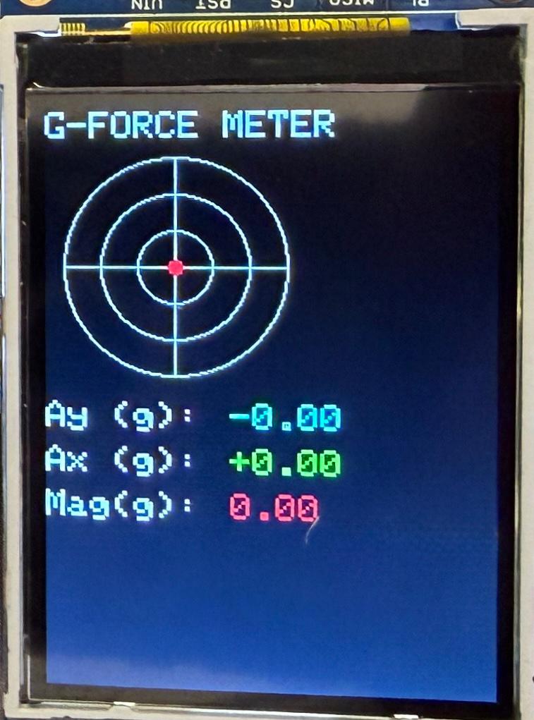
}5) G-Force meter rendering: erase/restore geometry and draw dot
The G-force meter has both static geometry (rings + crosshair) and a dynamic dot. We redraw the static geometry whenever the dot moves because erasing the dot can cover parts of the rings underneath. The dot position is computed in pixels from acceleration, then clamped to the meter radius to keep it on-screen. We chose values that seemed reasonable enough for the dot to not exceed the boundaries of the ring (we are of course not driving an F1 vehicle).
// Base meter geometry (rings + crosshair)
static void draw_gforce_meter_base(void)
{
	tft_drawCircle(GF_CX, GF_CY, GF_R, ILI9340_WHITE);
	tft_drawCircle(GF_CX, GF_CY, GF_R * 2 / 3, ILI9340_WHITE);
	tft_drawCircle(GF_CX, GF_CY, GF_R / 3, ILI9340_WHITE);

	tft_drawLine(GF_CX - GF_R, GF_CY, GF_CX + GF_R, GF_CY, ILI9340_WHITE);
	tft_drawLine(GF_CX, GF_CY - GF_R, GF_CX, GF_CY + GF_R, ILI9340_WHITE);
}
if (ui_state == UI_GFORCE)
{
float ax_g = accel_f[0];
float ay_g = accel_f[1];
// Pixels-per-g scaling based on ring spacing
float px_per_g = (float)GF_R / (3.0f * GF_G_PER_RING);
// Map Ay -> X and Ax -> Y (positive Ax moves dot DOWN)
float dx = -ay_g * px_per_g;
float dy = ax_g * px_per_g;
// Clamp to meter radius so dot stays inside the circle
float r2 = dx*dx + dy*dy;
float R = (float)GF_R;
if (r2 > R*R)
{
float scale = R / sqrtf(r2);
dx *= scale;
dy *= scale;
}
int x = GF_CX + (int)dx;
int y = GF_CY + (int)dy;
if (x != gf_prev_x || y != gf_prev_y)
{
// Erase old dot
tft_fillCircle(gf_prev_x, gf_prev_y, 4, ILI9340_BLACK);
// Restore geometry so rings/crosshair never get eaten
draw_gforce_meter_base();
// Draw new dot
tft_fillCircle(x, y, 4, ILI9340_RED);
gf_prev_x = x;
gf_prev_y = y;
}
// Numeric readouts below meter
tft_setTextSize(2);
tft_setTextColor2(ILI9340_CYAN, ILI9340_BLACK);
tft_setCursor(100, 160);
snprintf(buf, sizeof(buf), "%+1.2f ", ay_g);
tft_writeString(buf);
tft_setTextColor2(ILI9340_GREEN, ILI9340_BLACK);
tft_setCursor(100, 185);
snprintf(buf, sizeof(buf), "%+1.2f ", ax_g);
tft_writeString(buf);
float mag_g = sqrtf(ax_g*ax_g + ay_g*ay_g);
tft_setTextColor2(ILI9340_RED, ILI9340_BLACK);
tft_setCursor(100, 210);
snprintf(buf, sizeof(buf), "%1.2f ", mag_g);
tft_writeString(buf);
}The dot update is only performed when the new position differs from the previous position, which saves draw calls (we found that this did not significantly improve performance, but left it in for good practice). Clamping to the radius also makes the meter behave nicely during hard acceleration or turns, (we have previously mentioned the issue of the dot leaving the circle).
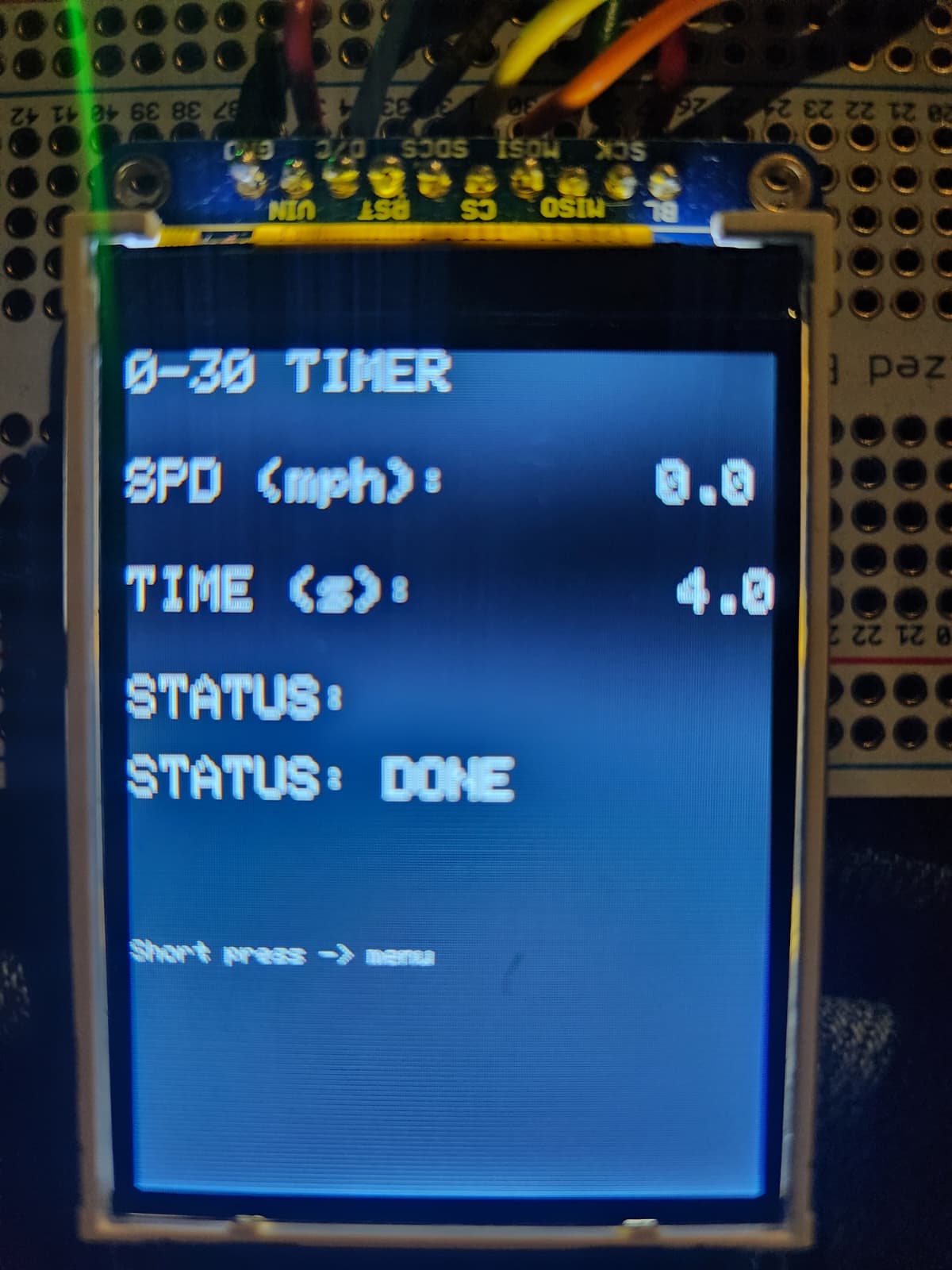
6) Timer screen update pattern: text status + numeric time
Both timer modes (0–60 and Autocross) follow the same UI pattern: the screen draws static labels once, then continuously rewrites three fields: a sensor input, a timer value, and a short status string. The status line is always padded with spaces to fully overwrite any previous text (similar to above). Below is an example pattern used throughout timer screens:
tft_setCursor(0, 150);
snprintf(buf, sizeof(buf), "STATUS: RUNNING     ");
tft_writeString(buf);

tft_setCursor(180, 80);
snprintf(buf, sizeof(buf), "%6.2f   ", display_time);
tft_writeString(buf);
Main Loop Structure & Update Rate
All peripherals are serviced in a single loop (IMU read + filter, GPS UART sentence assembly + parse, input decode, UI updates). The only interrupt-driven logic is PPS where we throttle the loop using a fixed sleep time, which produces a responsive UI and stable sensor readouts whie maintaining performance. The 20 ms sleep yields an effective update rate of ~50 Hz for the UI and IMU-derived features, while GPS data is naturally refreshed at its output rate (we chose 1 Hz, though this could have been increased in later iterations).
Intellectual Property Considerations
The closest devices that exist on the market are GPS devices that provide drivers with their speed and location. We did not find a device that was tailored for Auto-Cross racing specifically.
Parts List
- RP 2040 ($5)
- Neo-7m Integrated Chip by HiLetGo ($11)
- Waterproof Active Antenna by QGP Supply ($13)
- Active buzzer (~$1)
- Toggle-switch Knob (~$3)
- 6-DoF IMU (MPU-6050) (~$4)
- Adafruit 240x320 2.2” TFT display (~$20)
- 2 Adafruit Universal PCBs (2x $4 = ~$8)
- 12V Cigarette lighter adapter by Heart Horse ($7)
- 8-32V to 3.3V (3A) DC/DC Buck Converter by DROK ($7)
Total Cost: approx: $81
Results of the design
Test data, Scope traces, Waveforms, etc.
We used a 20V power supply connected with alligator clips to the Cigarette Adapter to supply 12V. Then we used an oscilloscope to measure the output of the DC/DC converter that is connected in series. We were able to confirm that the desired output of 3.3V was achieved.
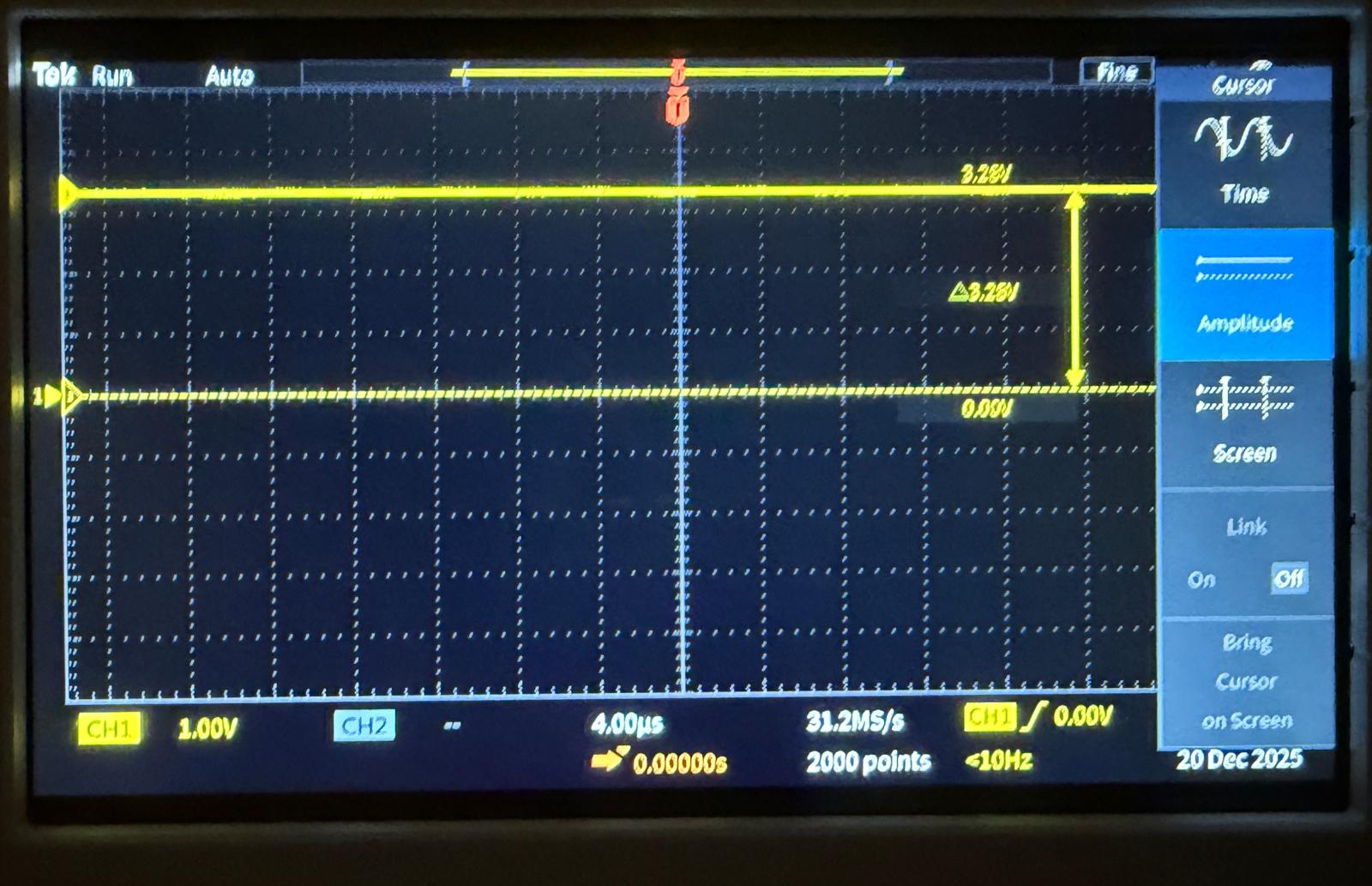
We also include an trace of the MPU-6050 SCL pin during I2C communication. We find it works at 3.3V, with transitions between 0V and ~3.28V.

Speed of Execution
The system takes about 5 seconds to boot up completely. The GPS chip, with the active antenna takes about 5-10 more seconds when in the car in a relatively sparse environment (outside, away from buildings/trees/etc.).
Accuracy
The GPS chip’s refresh rate is 1Hz. This could likely be increased, but we found that this refresh rate is reasonable in practice. In practice we notice a speed accuracy of about +/- 1km/h. Similarly for the IMU there is some static error of about 0.03 G's in any given direction. However, these errors do not seem to interfere with the effective operation of the device.
Enforcing Safety
We purchased parts from reputable manufacturers and sources, such as DigiKey and Amazon. We used a DC/DC converter to reduce the power output to a standard 3.3V. All of the modules we use are quite low power, pulling very little current for operation leading to a very safe design.
Usability
The usability of our project is something that we really prioritized. We decided to power the device from a standard 12V cigarette lighter as those are common in almost any car starting from the 1950s. This is compared to powering the chip with a USB which would limit its usability to cars post 2010s. Secondly, the user interface is quite simple. After simply plugging in the power cord, the device boots up and displays a very simple menu to navigate. This allows the user to easily cycle through the various functions.

Demo
Conclusion
Overall, we are very happy with the final outcome. There are definitely some aesthetic improvements that could be made to make the project look more like a finished product. However, in terms of functionality, we were able to produce the desired results. We are able to accurately measure 0-30 times, the AutoCross function allows for accurate timing of course runs without distracting the driver. Also, the G-Force meter provides meaningful information on your real-time driving when making sharp turns, or breaking and accelerating heavily.
We were able to successfully integrate multiple peripherals over different interfaces: the MPU6050 IMU on I2C, the GPS module on UART1 (with PP), and the TFT display for the UI. Our code continuously reads IMU data, applies software low-pass filtering to reduce noise, and feeds those values to both the numeric views and the live G-force meter. At the same time, the GPS parsing logic decodes NMEA sentences to provide live latitude, longitude, time, and speed, which are then used by the GPS info screen as well as the 0–30 timer and Auto-Cross timing logic.
The user interface design also turned out to be effective. Using a single rotary encoder with a push button, we implemented a menu system that lets the driver switch between modes without having to clutter the hardware with extra buttons. Visual feedback on the TFT, combined with audible beeps from the buzzer during countdowns and at the end of runs, helps the driver interact with the system while still being able to keep attention on the road.
For future iterations, there are a few aspects that we could improve on. On the hardware side, we could design a custom PCB and enclosure to further clean up wiring, improve durability, and give the project a more professional appearance. On the software side, additional features such as data logging, more advanced filtering, and configurable thresholds for the timers could make the device even more useful for performance driving. Regardless, our current implementation demonstrates that our design choices seemed sound.
Appendix A: Permissions
Project on the course page
The group approves this report for inclusion on the course website.
Project on the course YouTube channel
The group does not approve the video for inclusion on the course youtube channel.
Appendix B: Hardware Images
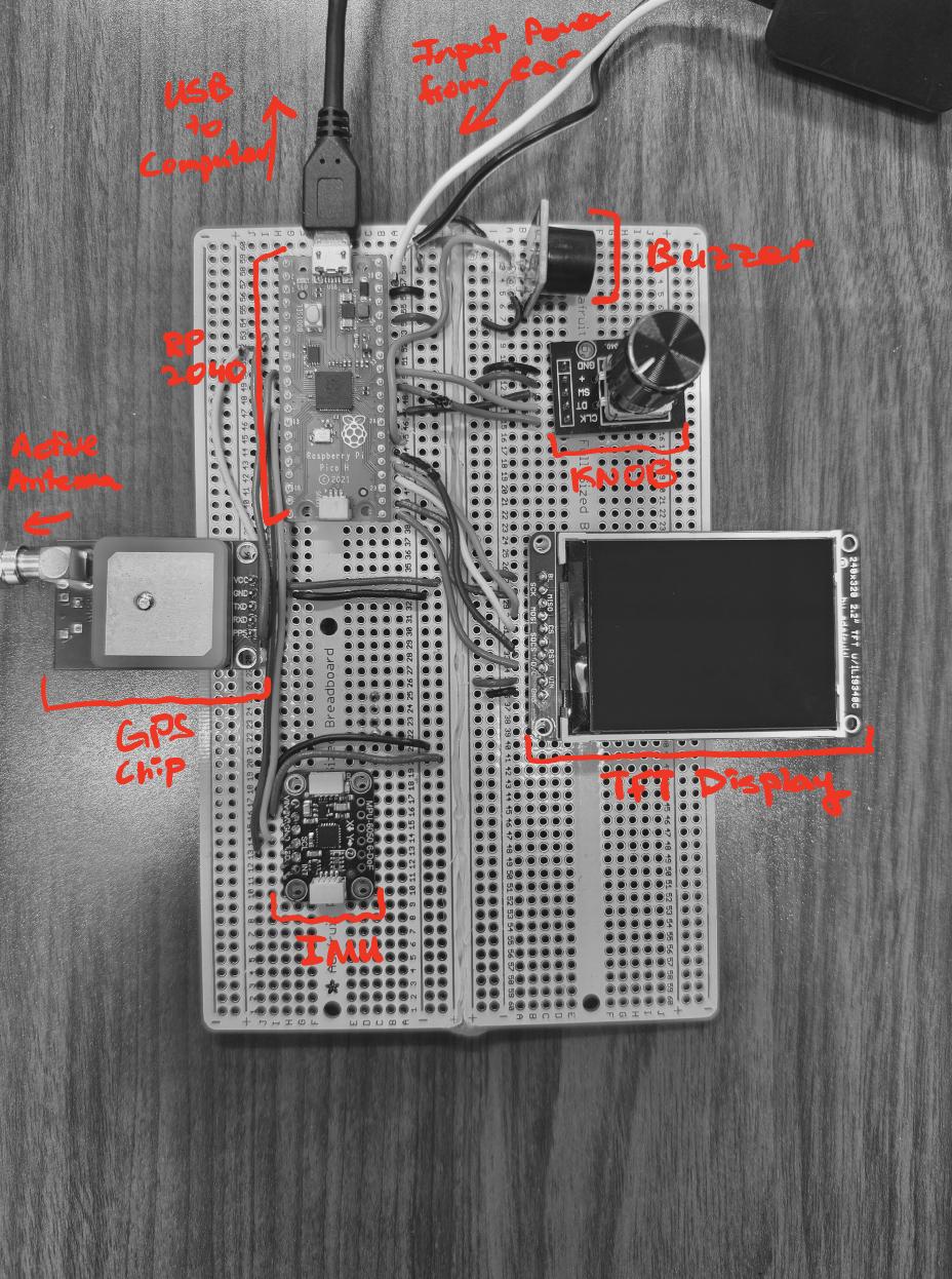
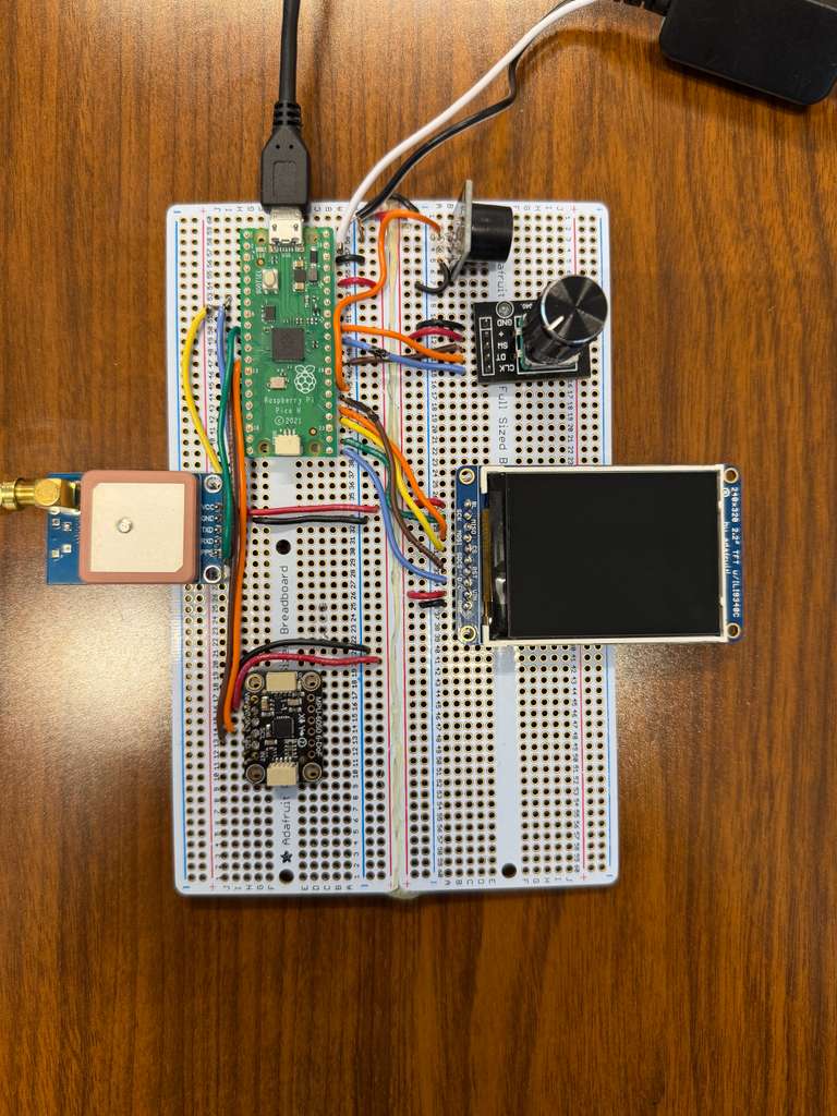
Physical Pin Diagrams for Peripherals
Appendix C: Draw Functions (Static Screen Layouts)
The UI rendering code is split into two parts: (1) one-time “draw” functions that create a screen’s static layout
(title text, labels, fixed geometry), and (2) lightweight per-loop updates that overwrite only the changing values.
Each draw_* function is called only when ui_redraw is set (i.e., on state transitions) to avoid
full-screen flicker and keep the main loop responsive.
- Static draw: clear screen, write labels/headers, draw fixed geometry (e.g., meter rings).
- Dynamic patch updates: use
snprintf+ trailing spaces and minimal redraw calls. - Consistency: every screen uses the same “draw once, then patch” pattern, which makes adding new screens easy.
draw_menu_screen() - Draws the menu title and all menu entries one time. The selection arrow is then updated
incrementally in the main loop (see “Menu: arrow-only incremental updates”).
static void draw_menu_screen(void)
{
	tft_fillScreen(ILI9340_BLACK);
	tft_setTextColor2(ILI9340_WHITE, ILI9340_BLACK);

	tft_setTextSize(3);
	tft_setCursor(10, 0);
	tft_writeString("Main Menu");

	tft_setTextSize(2);

	tft_setCursor(20, 30);
	tft_writeString("Accel");
	tft_setCursor(20, 60);
	tft_writeString("Gyro");
	tft_setCursor(20, 90);
	tft_writeString("GPS");
	tft_setCursor(20, 120);
	tft_writeString("G-Force");
	tft_setCursor(20, 150);
	tft_writeString("0-30 Timer");
	tft_setCursor(20, 180);
	tft_writeString("AutoCross");

	// Forces arrow redraw on first menu update
	prev_menu_sel = -1;
}
draw_accel_screen() - Static layout for acceleration screen (axis labels + placeholders). Live values are written
each loop using the formatting/overwrite technique shown earlier.
static void draw_accel_screen(void)
{
	tft_fillScreen(ILI9340_BLACK);
	tft_setTextColor2(ILI9340_WHITE, ILI9340_BLACK);

	tft_setTextSize(3);
	tft_setCursor(10, 0);
	tft_writeString("Accel (g)");

	tft_setTextSize(2);
	tft_setCursor(0, 40);
	tft_writeString("Ax:");
	tft_setCursor(0, 70);
	tft_writeString("Ay:");
	tft_setCursor(0, 100);
	tft_writeString("Az:");

	// Placeholders (overwritten during live update)
	tft_setCursor(60, 40);
	tft_writeString("0.0000   ");
	tft_setCursor(60, 70);
	tft_writeString("0.0000   ");
	tft_setCursor(60, 100);
	tft_writeString("0.0000   ");
}
draw_gyro_screen() - Static layout for gyroscope screen. Uses the same formatting strategy as the accel screen.
static void draw_gyro_screen(void)
{
	tft_fillScreen(ILI9340_BLACK);
	tft_setTextColor2(ILI9340_WHITE, ILI9340_BLACK);

	tft_setTextSize(3);
	tft_setCursor(10, 0);
	tft_writeString("Gyro");

	tft_setTextSize(2);
	tft_setCursor(0, 40);
	tft_writeString("Gx:");
	tft_setCursor(0, 70);
	tft_writeString("Gy:");
	tft_setCursor(0, 100);
	tft_writeString("Gz:");

	tft_setCursor(60, 40);
	tft_writeString("0.0000   ");
	tft_setCursor(60, 70);
	tft_writeString("0.0000   ");
	tft_setCursor(60, 100);
	tft_writeString("0.0000   ");
}
draw_gps_screen() - Draws GPS labels and placeholder strings. The live update path overwrites values only when
gps_has_fix / gps_has_time_speed become available.
static void draw_gps_screen(void)
{
	tft_fillScreen(ILI9340_BLACK);
	tft_setTextColor2(ILI9340_WHITE, ILI9340_BLACK);

	tft_setTextSize(3);
	tft_setCursor(10, 0);
	tft_writeString("GPS");

	tft_setTextSize(2);
	tft_setCursor(0, 40);
	tft_writeString("Lat:");
	tft_setCursor(0, 70);
	tft_writeString("Lon:");
	tft_setCursor(0, 100);
	tft_writeString("Time:");
	tft_setCursor(0, 130);
	tft_writeString("Spd:");

	// Placeholders
	tft_setCursor(60, 40);
	tft_writeString("No fix   ");
	tft_setCursor(60, 70);
	tft_writeString("No fix   ");
	tft_setCursor(60, 100);
	tft_writeString("--:--:-- EST ");
	tft_setCursor(60, 130);
	tft_writeString("--.- km/h   ");

	// PPS status line
	tft_setTextSize(1);
	tft_setCursor(0, 160);
	tft_writeString("PPS: --             ");
}
draw_gforce_screen() - Draws the static meter geometry, axis labels, and initializes the dot.
The update path erases and redraws the dot while restoring geometry as needed.
static void draw_gforce_screen(void)
{
	tft_fillScreen(ILI9340_BLACK);
	tft_setTextColor2(ILI9340_WHITE, ILI9340_BLACK);

	tft_setTextSize(3);
	tft_setCursor(10, 0);
	tft_writeString("G-Force");

	// Static meter geometry
	draw_gforce_meter_base();

	// Labels below meter
	tft_setTextSize(2);
	tft_setTextColor2(ILI9340_CYAN, ILI9340_BLACK);
	tft_setCursor(0, 160);
	tft_writeString("Ay:");

	tft_setTextColor2(ILI9340_GREEN, ILI9340_BLACK);
	tft_setCursor(0, 185);
	tft_writeString("Ax:");

	tft_setTextColor2(ILI9340_RED, ILI9340_BLACK);
	tft_setCursor(0, 210);
	tft_writeString("|a|:");

	// Initialize dot at center
	gf_prev_x = GF_CX;
	gf_prev_y = GF_CY;
	tft_fillCircle(gf_prev_x, gf_prev_y, 4, ILI9340_RED);
}
draw_zero_to_sixty_screen() - Draws static labels for the 0–30 timer screen. The update path overwrites the
speed/time/status fields every loop.
static void draw_zero_to_sixty_screen(void)
{
	tft_fillScreen(ILI9340_BLACK);
	tft_setTextColor2(ILI9340_WHITE, ILI9340_BLACK);

	tft_setTextSize(3);
	tft_setCursor(10, 0);
	tft_writeString("0-30 Timer");

	tft_setTextSize(2);
	tft_setCursor(0, 40);
	tft_writeString("Speed:");
	tft_setCursor(0, 80);
	tft_writeString("Time:");

	tft_setCursor(0, 150);
	tft_writeString("STATUS: READY       ");

	// Placeholders
	tft_setCursor(90, 40);
	tft_writeString("--.- mph   ");
	tft_setCursor(90, 80);
	tft_writeString("--.--      ");
}
draw_autocross_screen() - Draws static labels for Auto-Cross mode, including countdown/status areas. The update
path rewrites the status/time and any “countdown step” text.
static void draw_autocross_screen(void)
{
	tft_fillScreen(ILI9340_BLACK);
	tft_setTextColor2(ILI9340_WHITE, ILI9340_BLACK);

	tft_setTextSize(3);
	tft_setCursor(10, 0);
	tft_writeString("AutoCross");

	tft_setTextSize(2);
	tft_setCursor(0, 40);
	tft_writeString("Accel:");
	tft_setCursor(0, 80);
	tft_writeString("Time:");

	tft_setCursor(0, 150);
	tft_writeString("STATUS: COUNTDOWN   ");

	// Placeholders
	tft_setCursor(90, 40);
	tft_writeString("--.-- g   ");
	tft_setCursor(90, 80);
	tft_writeString("--.--     ");
}
Appendix D: Tasks by Team Member
- The initial breadboard was constructed equally between Zach and Andranik.
- The soldering to the universal PCB was done by Andranik.
- On the software side. Initial code was written by Andranik and improved by Zach.
- Software testing was done by Zach. Hardware verification was done by Andranik.
- Attaining data/photos were done equally between Zach and Andranik.
References
- P. Sharma, “PIO-Based TFT Driver (TFTMaster) Documentation,” https://parthssharma.github.io/Pico/TFTLibrary.html
- ECE 4760 / 5730 Course Website, Cornell University, https://ece4760.github.io/
- “Understanding GPS and NMEA Sentences,” YouTube tutorial, https://www.youtube.com/watch?v=CLsXnSOIYMg
- Raspberry Pi Foundation, “RP2040 Datasheet,” https://datasheets.raspberrypi.com/rp2040/rp2040-datasheet.pdf
- InvenSense, “MPU-6050 6-Axis Motion Tracking Device Datasheet,” https://invensense.tdk.com/wp-content/uploads/2015/02/MPU-6050-Datasheet.pdf
- u-blox, “NEO-7 GNSS Module Data Sheet,” https://content.u-blox.com/sites/default/files/products/documents/NEO-7_DataSheet_%28UBX-13003830%29.pdf
- Adafruit Industries, “2.2” TFT LCD Display (ILI9340/ILI9341) Pinouts,” https://learn.adafruit.com/2-2-tft-display/pinouts
- Raspberry Pi Pico Pinouts, https://datasheets.raspberrypi.com/pico/Pico-R3-A4-Pinout.pdf
- Amazon product listings for GPS module, antenna, DC/DC converter, and power adapter (listed above).