DigiDrum is a low cost solution for those who want to play the drums but may not want to purchase expensive instrumental equipment or have the space to fit a drumset.
DigiDrum is a combination of a virtual and physical emulator of a three instrument drumset, allowing users to create realistic and responsive musical noise by “striking” non-existent drums and cymbals with real life drum sticks and a kick pedal. In other words, although a user holding the drum sticks and tapping the kick pedal may not be hitting actual drums and hi-hats, the same motion that would cause the instrument to make noise in real life causes noise to be played on our drumset simulation system.
This behavior is achieved by tracking the acceleration of both drumsticks separately, with software constantly filtering through all the noisy movement of each drumstick until it registers an acceleration pattern that corresponds to a striking motion. An MPU6050 on either drumstick allows the user to passively send data to the RP2040 about what sort of motion they are currently engaged in, creating a user experience that strongly feels like playing a real drumset. For our project, the drumstick in the user’s right-hand was associated with a hi-hat and the left-hand corresponded with a snare drum. So upon triggering a right handed strike, a hi-hat noise came out of the speakers, and a snare noise came out of a different set of speakers when the left hand made a striking motion. The kick pedal itself outputs a small electric pulse when struck, so this signal was amplified and used in our system to trigger a bass drum sound to be played through a subwoofer.
The purpose behind this project was to construct an artificial user experience that resembled, and importantly felt like, the true system. This sort of simulation is done for many aspects of life: flight simulators, virtual reality and augmented reality technology, and even some videogames and arcade games. These sorts of systems blur the lines between the barrier of the physical and digital worlds, and it can allow for interesting and novel user experiences. In particular, we decided to develop a simulated drumset because of universality. While percussion doesn’t always take the form of a standard drumset, the rhythm and music of percussion instruments can be heard throughout history and across cultures. Additionally, it’s just plain fun to make loud noises, even if they don’t sound good!
The rationale behind our project was simple: we wanted to create a hybrid of a virtual and physical device that felt and sounded like a real drumset and that was fun to play. We decided to move forward with this idea after seeing some projects similar to it on Tik Tok, and we decided that it would be both challenging and engaging to try it ourselves. The video that inspired us can be found here: Inspiration Video
In order to have this project come to fruition, we needed to communicate with two IMUs in order to track the movement of both drumsticks separately, we needed three separate DMA channels setup for our three different noises (snare, hi-hat, and bass), and we needed a way to graphically visualize the data we were gathering and generating within our program.
The beating heart of our project is our Interrupt Service Routine (ISR). This ISR, named “drum_check_irq”, interrupts whatever code is taking up compute, pausing the rest of the system every 1500 microseconds so that the ISR can go through its own logic. This interrupt frequency of ~666 Hz was chosen such that it was fast enough to gather more than enough acceleration data in order to accurately register a user's strike of an instrument, but slow enough to allow the ISR to be able to successfully communicate with both of the IMUs. To visualize how quickly the ISR runs, please refer to Figure 3.
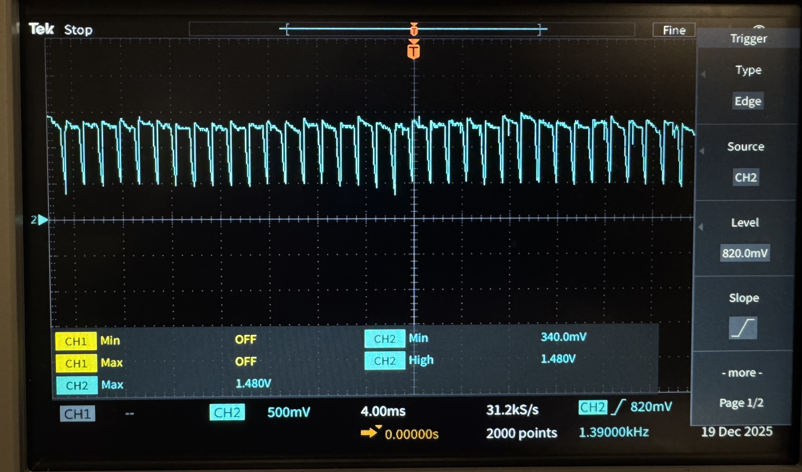
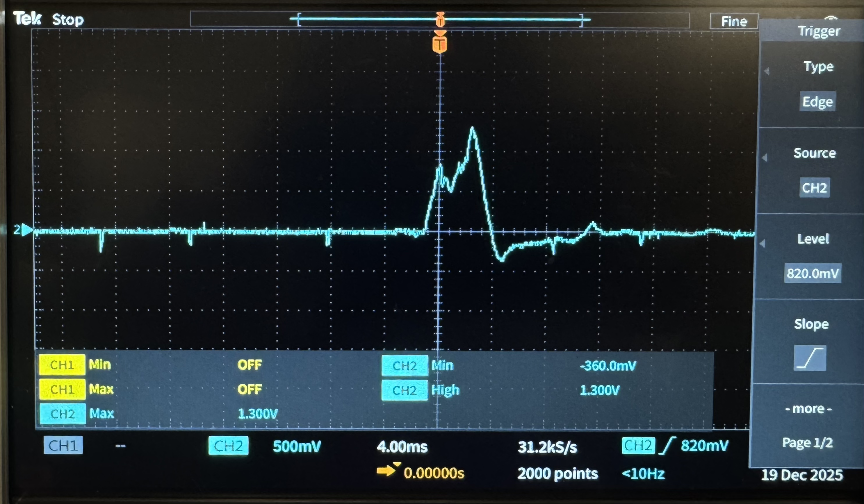
Within the ISR, there is logic to determine whether or not a user has “struck” either a drum or the hi-hat. This is done by first reading the z-acceleration from both IMUs, low passing those values in order to reduce noise, and then adding them to their own ring buffer depending on which drumstick the IMU was attached to. After adding both the left hand data and the right hand data to their respective ring buffers, we then send the data through a comb filter, which essentially sifts through the acceleration data in order to find a specific pattern of values that we recognize happens whenever a user makes a striking motion. If the output of this comb filter is larger than a programmer defined magnitude, then this signals to the system that the user did in fact intend to strike an instrument, as opposed to just waving the drumsticks around. Upon a valid striking motion, the ISR triggers the DMA to playback the corresponding noise. If the user made a right-handed strike, the DMA outputs a hi-hat noise to the DAC, and if it was a left-handed strike, the DMA sends out the data corresponding with a snare noise. Similarly, when the kick stand was kicked, we sent the electrical pulse generated through an amplifier and a voltage divider and sent the result of the amplification to a GPIO on RP2040. The amplification process, done through a comparator circuit design as shown in Figure 9, was necessary because the kick stand was unable to produce a large enough voltage for the RP2040 to register it as a logical high input. The original output from the kick stand and the amplified output can be seen in Figures 1 and 2. With the addition of the amplification, after going through the logic of both the right and left handed drumsticks, the ISR then checked to see if the GPIO associated with the kick pedal was high. In the case that it was, the ISR signalled to the DMA to send the data for a bass sound to the subwoofers. At the very end of the ISR, it semaphored into a protothread that graphed all of this data.
Aside from the ISR, we implemented many protothreads in order to help our system come to fruition. The “protothread_ui” thread allowed users to interact with the VGA display by implementing a debouncing state machine that would take the user in between the data display VGA and a game display upon the push of a button. This protothread ran on its own every 0.02 seconds, allowing it to accurately detect valid button presses from the user but not taking up too much computational space.
The “protothread_vga_display” actually didn’t run on its own, and was triggered to be run through a semaphore at the end of the ISR after all the acceleration and strike data had been updated. This protothread used the VGA display to create one of two screens. The first is a screen with two graphs on it used for visualization of data about the system. The top graph displayed the realtime acceleration data from both drumsticks, allowing users to visualize how their movements are interpreted by the IMU. On the graph below this one, the output of the comb filter for both hands were displayed on the same graph. It was important to display both of these data during hte making of the system because it allowed us to make a valid instrument strike that “felt” correct, and then look at the corresponding acceleration and combfilter data to determine how we should have the RP2040 interpret the data. This took many trials, and this process will be discussed in a later section. The second screen associated with this protothread displayed a simple, three instrument, pixelated drum set. Above the drumset, there were two horizontal lines, and different colored balls would fall from the top of the screen at a steady pace until they entered the space between the two horizontal lines. This was the game mode of DigiDrum, with the goal that when a ball that is hovering over a specific instrument enters the space between the two horizontal lines, the user should strike that same instrument either with their drumsticks of the foot pedal at the same instant. This allowed for users to time themselves, as well as practice drumming to a specified beat, with the VGA display doubling as a metronome. When the user struck any of the instruments, they lit up with different colors depending on the instrument. The protothread determines which VGA screen to draw depending on the state of the finite state machine discussed earlier in the “protothread_ui”.
The “protothread_serial” allowed for the user to change parameters of the system through a serial interface with the RP2040 without having to change the code and reupload it. For example, the user could change the speed that the VGA displayed the acceleration data, the value of the counter for valid hits in the case that they wanted to reset it, and also the threshold that is used to determine if a strike is indeed a valid strike, as discussed earlier.
Finally, the “protothread_display_values” thread was used to display data textually as opposed to graphically, which was useful for data collection and debugging.
All of these protothreads ran on Core 0 of the RP2040. The only thing on Core 1 was the I2C initialization and devices. This was implemented so that we could isolate the I2C devices from the protothreads so that they don’t latch each other in the case that the I2C communication fails. In order to initialize the I2C devices, we set up GPIO pins that were used to power the I2C devices so that they would turn off when the RP2040 was rebooting and wouldn’t cause the system to hang when no I2C address was found. On Core 0, however, there was no I2C initialization, but that is where the IRQ setup for the ISR occurred, as well as setting up the process for the DMA to send audio data to the DAC. Because each DAC has two outputs, and we wanted three independent sounds, we needed to use two separate DACs that were each on their own SPI channel. This allowed for users to play all three instruments (snare, hi-hat, and bass) at the same time, and none of the sounds would interrupt the other, creating a realistic feel.
One hardware/software tradeoff that we chose to make was to not have the drumsticks and foot pedal be completely, physically isolated from the RP2040 that controls the VGA screen. This could have been done by giving each drumstick its own RP2040 and IMU, as well as giving the foot pedal its own RP2040. Then these three additional microcontrollers could have communicated with the main microcontroller that controlled the VGA display, allowing for completely isolated physical systems and giving the user a full range of motion. However, we chose to wire both of the drumsticks and the footpedal directly to one RP2040 because, realistically, a user wouldn’t need full range of motion in both hands when playing a drumset; they just need to be able to play in front of them and sometimes to the side. Additionally, including this extra hardware onto the drumsticks could have made them awkward to hold and possibly throw off the balance of the stick, which may feel odd to the user. Therefore, we sacrificed the elegance of physically isolated systems and the software design for communication between RP2040’s for a simpler hardware design that met the requirements of our project
To our knowledge, there are no existing patents, copyrights, or trademarks which are relevant to our project. There was some inspiration from “Guitar Hero”, a video game created by RedOctane where users play a fake guitar by following guides on a screen.
We did use online resources in order to find samples of instrument noises. We downloaded our hi-hat noise that is in the creative commons from soundcamp.com, and we downloaded both our snare and bass noise from pixabay.com, which we were also free to use.
We stored our audio files in Flash memory. We were able to do this using a script written in python using the help of AI. The purpose of this was to allow accurate sounding audio samples to be stored in flash memory (because there isn’t enough RAM) and to be played back without any runtime audio decoding and formatting.
This script takes standard .wav audio files and transforms them into C header files containing pre-formatted 16-bit command words suitable for direct transmission to our MCP4822 12-bit DACs over SPI.
The script can remove leading and trailing silence. This reduces memory usage and eliminates long stretches of zeros or near-zeros that would otherwise waste playback time. After trimming, the audio data is downsampled by an integer factor using simple decimation. In the current configuration, every second sample is kept and the rest are discarded. This reduces the total number of samples by roughly a factor of two. The downsampling is purely a data reduction step, and there were not detectable differences in audio playback with downsampled datasets besides the duration of the audio.
The remaining samples are then scaled from their signed integer range into the 12-bit unsigned range required by the MCP4822 DAC. Each 12-bit DAC code is then packaged into a full 16-bit MCP4822 command word. Here we also set the upper control bits to specify which DAC channel to use (A or B). By performing this packing step offline, the microcontroller does not need to manipulate bits or apply configuration flags at runtime; it can simply transmit each 16-bit value over SPI as-is.
The script writes all of this data into a C header file. The audio data itself is stored as a const uint16_t array containing the pre-formatted MCP4822 command words. It also listed a couple relevant variables, such as the length of the array.
Triggering playback happens inside our interrupt handler drum_check_irq(). We have a repeating timer interrupt using the RP2040 alarm hardware so that every 0.0015 seconds we sample data from our IMUs, run our detection logic, and decide whether a hit occurred. When a hit is detected, we trigger the DMA channel corresponding to the correct audio sample. The current implementation has 3 DMA channels over 2 DACs. In the future more can be added, but in our current implementation we are limited by the number of SPI channels on the RP2040. A right-hand hit triggers the hi-hat DMA, a left-hand hit triggers the snare DMA, and the pedal GPIO triggers the kick DMA.
Please note, that none of our group members play the drum, or are particularly musically/drum talented.
DigiDrum’s hardware is centered around a single RP2040 (Raspberry Pi Pico) that ties together sensing, audio playback, and visualization, as we have used throughout this course. The Pico reads motion from two separate IMU sensors mounted on drumsticks, detects a kick-pedal press through a conditioned digital input, streams three drum samples to external DACs for audio output, and drives a VGA display that shows live plots and a simple rhythm “game” interface. A photo of the final breadboard build is shown in Figure 10.
Each drumstick carries its own MPU6050 IMU breakout board, attached using tape and zip ties so the sensor does not shift during play. The two IMUs are read independently so the left and right hands can trigger different instruments (snare and hi-hat). To keep the sensing reliable and avoid bus conflicts, the IMUs are placed on two separate I2C connections: the right-hand IMU uses GPIO 8 (SDA) and GPIO 9 (SCL), while the left-hand IMU uses GPIO 3 (SDA) and GPIO 11 (SCL). We powered each IMU through GPIO-controlled “power” pins (GPIO 28 for the right IMU and GPIO 4 for the left IMU). This allowed the software to power-cycle the sensors during fault recovery if I2C ever entered a stuck state, which significantly improved robustness during long play sessions.
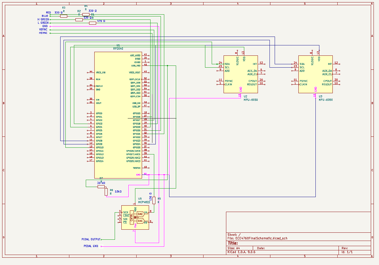
Kick detection uses a small electrical pulse produced by the pedal, but the raw pedal voltage is not consistently large enough to be read as a logic HIGH by the RP2040. To make the kick reliable, we conditioned the pedal output using an MCP6242 op-amp configured as a comparator (used as a thresholder). The pedal signal is fed into the comparator’s non-inverting input (VINA+), and a fixed reference threshold is fed into the inverting input (VINA−). The threshold is generated from 3.3 V using a resistor divider (30 kΩ from 3.3 V to the node and 10 kΩ from the node to ground), which produces approximately 0.825 V. If the pedal pulse rises above this threshold, the comparator output saturates high near 3.3 V; otherwise it stays near 0 V. The comparator output is then routed through a 330 Ω series resistor into GPIO 27 on the Pico, giving a clean digital “kick pressed” signal that the firmware can sample inside the interrupt routine.
Audio playback is handled with two MCP4822 12-bit DACs so we can output three independent drum sounds without one sample interrupting another. The DACs are driven over SPI using DMA-based streaming, which keeps the CPU free for IMU sampling, strike detection, and VGA drawing. One DAC is placed on SPI0 and is used for the hi-hat and snare channels, and the second DAC is placed on SPI1 and is used for the kick channel. In our wiring, SPI0 uses GPIO 2 (SCK), GPIO 7 (MOSI), and GPIO 5 (CS), and SPI1 uses GPIO 14 (SCK), GPIO 11 (MOSI), and GPIO 13 (CS). Each DAC output is routed to a 3.5 mm audio jack that feeds powered speakers; the kick output is sent to a subwoofer for a more realistic bass-drum feel. Because the firmware stores each audio sample as pre-formatted 16-bit MCP4822 command words, the DMA can transmit directly into the SPI data register with minimal runtime overhead.
We utilized speakers from the lab, using one speaker per noise, with a nice subwoofer for the kick drum. We ran into some noise from these audio jacks, which was fixed by rewiring our system to make sure that all of our wires and grounds were working well.
For visualization and debugging, DigiDrum outputs to a VGA monitor using the standard RP2040 VGA driver used in the course previously. Horizontal and vertical sync are generated on GPIO 16 (HSYNC) and GPIO 17 (VSYNC). The color channels are produced with small resistors: GPIO 18 through a 470 Ω resistor and GPIO 19 through a 330 Ω resistor drive green intensity, while GPIO 20 through 330 Ω drives blue and GPIO 21 through 330 Ω drives red, with VGA ground tied to RP2040 ground. This VGA output is used both as a development tool (plotting acceleration and comb-filter values in real time) and as the user-facing interface (the drumset game mode).
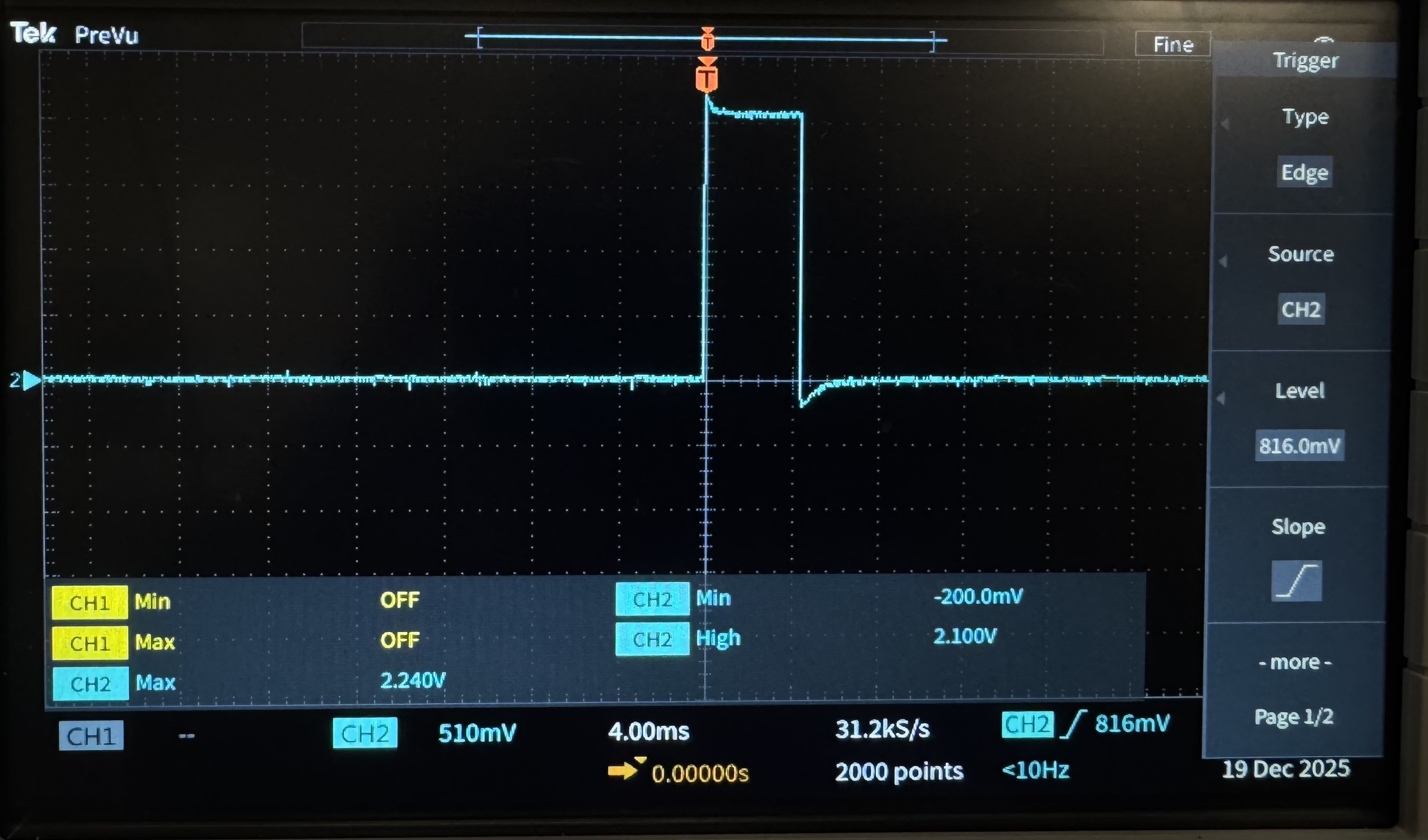
Finally, for testing, we added a dedicated observability pin so we could measure interrupt timing and quickly diagnose lockups. GPIO 6 is toggled high at the start of the drum-check ISR and low at ISR exit. On an oscilloscope, this produces a pulse train at the interrupt rate (every 1.5 ms). If the system ever became stuck inside the ISR, this line would latch high, giving an immediate, hardware-level indication of the failure mode.
Below is the full bill of materials for DigiDrum. The build uses a single RP2040 as the controller, two MPU6050 IMUs mounted to drumsticks for motion sensing, an MCP6242 used as a comparator to cleanly detect the kick pedal, and two MCP4822 DACs to output three independent audio channels (hi-hat, snare, kick) to external speakers. VGA output uses the standard resistor ladder interface for sync and RGB signals.
| Qty | Item | Notes |
|---|---|---|
| 1 | RP2040 (Raspberry Pi Pico) | Main microcontroller |
| 2 | Breadboard(s) | One for main build, one optional for cleaner pedal/comparator wiring |
| 2 | MPU6050 IMU breakout | One per drumstick (separate I2C buses) |
| 2 | MCP4822 12-bit DAC | Two SPI buses; 3 channels used total |
| 3 | 3.5 mm audio jack outputs | Hi-hat, snare, kick → powered speakers/subwoofer |
| 1 | MCP6242 dual op-amp | Used as comparator for kick pedal thresholding |
| 3 | 330 Ω resistor | Used in VGA ladder + comparator output series resistor (as built) |
| 1 | 470 Ω resistor | VGA ladder (green channel intensity bit) |
| 1 | 30 kΩ resistor | Threshold divider (top resistor) |
| 1 | 10 kΩ resistor | Threshold divider (bottom resistor) |
| 1 | Kick pedal | Produces raw pulse that is thresholded by comparator |
| 2 | Drumsticks | Physical input devices; IMUs mounted with tape/zip ties |
| — | Jumper wires | Interconnects between sensors/DACs/VGA/breadboard |
| — | Tape + zip ties | Mount IMUs securely to drumsticks |
Overall, the hardware design intentionally favors a simple controller architecture as the sensors remain lightweight on the drumsticks, and all computation and audio streaming happens on the Pico. The tradeoff is that the sticks and pedal are tethered by wires rather than being fully wireless, but the result is a reliable, low-cost build that is easy to reproduce on a breadboard while still feeling responsive and realistic to play.
Above is our game, which now just functions as a metronome, with the bpm for each instrument able to be controlled by the user in the serial monitor.
One of the main things that we had to implement but that did not initially work for quite some time was figuring out what set of conditions should the RP2040 be looking for when attempting to determine if the user has made a valid striking motion. This was an issue for us because we had not anticipated that when the user is bringing the drumstick up, to subsequently bring it down and make a strike, their arm oscillates a little bit at the top of this movement where the armspeed is momentarily zero. This oscillation, when looked at on the VGA graph, had the exact same shape that we had associated with a valid strike motion, but it was obvious to the user that it wasn’t. Similarly, during a valid strike motion, there too was some oscillation, causing part of the acceleration data to look instead like an upwards strike, not a downwards one. So when the drumstick was moving up and stopped, which shouldn’t trigger a sound to play because the user has “struck” anything, the acceleration data looked like it had moved up, but then immediately afterwards there was a small downward acceleration that made it look like the user had tried to strike an instrument. The opposite issue was true when the user was actually trying to strike the instrument. For better visualizations of this, it may be helpful to look at the top graph in Figure 4, as well as Figures 6, 7, and 8.
Initially, we thought we could avoid this issue by just using the acceleration data from the IMU, waiting for when the z-acceleration became higher than some arbitrary threshold. Our assumption was that the z-acceleration wouldn’t get higher than the threshold unless it was moving down quickly, as would happen during a strike. However, we found that this was an unreliable method of registration and would sometimes miss valid strikes and register invalid ones. In order to visualize how the upwards and downwards movement of the drumsticks affected the acceleration and gyroscope data, please refer to Figures 6 and 7. For a visualization of when an invalid strike might actually be registered as a valid strike with this method, refer to Figure 8.
We then tried to additionally use the gyroscope data to help differentiate between a general upwards motion and a downwards one. Here, too, we ran into the issue that its success was never fully accurate. After this we tried a completely new method, where we kept drawing data from the IMU, and once the z-acceleration had gone from below equilibrium to above equilibrium or vice versa, we would register a valid strike or an invalid strike, respectively, then we would either register of not register a strike and ignore the next interval of data points. The idea here was that we did not expect users of our system to attempt to drum too fast, and since part of the acceleration data that messed with our logic was always the second half of the data, if we then register the beginning motion as a valid strike, then count is as a strike and don’t take measurements for a certain amount of time. Similarly, if the motion was not a strike, then don’t register a strike but still don’t collect data for a certain amount of time. This way, both the false invalid hit and the false valid hit would be completely ignored by the program.
This idea worked with different effectiveness for different wait periods where the data from the IMU was not obtained, but ultimately this approach led to worse results than the previous two. When discussing a different approach to this problem with the course staff, it was suggested to try using a ring buffer and combfilter instead. The ring buffer allowed us to keep track of some of the history of the acceleration data, which seemed important because visually we were able to differentiate between the acceleration data of a valid strike from an invalid strike based on what was happening around the time of the strike, so some system history was necessary to make this differentiation. We made the ring buffer 256 indices long and traversed through the indices with a counter that continued to count beyond 256. This worked because we would take the counter value and mask it with 0xFF, essentially truncating the counter to within the range of 0 to 255, and if the counter ever overflowed, it would just go from 255 back to 0, and the ring buffer would wrap around to the first index. This allowed us to keep a history of the data in an array without having to keep track of where we were in the array, and it also made accessing previous datapoints in the array much easier, which we needed for the combfilter.
The combfilter is a type of filter that takes in a signal, in our case an array of the 256 most recent z-acceleration data, and multiplies some of the data points by predefined weights. These new products are then summed together, and this is the output of the combfilter. In order to implement it, the weights all have to sum to zero so that when the data is noisy, the sum of the products will be zero and the combfilter will not have found what it was sifting for. However, if you place the weights at specific data point regions and are careful with how you distribute the weighting, then you can create a filter that creates an output sum that is very high when the data in the filter matches the data that you are interested in registering. For the DigiDrum, this meant building a combfilter that could sift through the past 255 acceleration data points and find when the acceleration pattern matched that of a valid strike motion. In order to determine where in the 256 length array the combfilter’s weights should be, and how positive or negative those weights should be, depended on the data input. After examining the shape of a valid strike and determining an ending point of the strike, where the acceleration went back to its equilibrium value, we were able to look back and determine which features of the strike pattern we wanted to prioritize and give high weighting. The shape that triggers the comb filter to output a large sum of products can be seen in Figure 5. After some tunning, this combfilter was successfully able to register a valid strike and ignore invalid strikes much better than our previous methods, and that is why it was used for the final product.
We encountered a hard-to-debug failure mode where the system would occasionally hang inside the drum-detection ISR immediately after a hit was detected and the DMA was triggered. We confirmed that we were getting stuck in our ISR using two independent observability methods. First, we relied on the VGA visualization that continuously plotted the IMU / complementary-filter signals; when the bug occurred, those plots stopped updating, indicating that we never reached the end of ISR and therefore never semaphored into our VGA protothread. Second, we instrumented the ISR with a dedicated GPIO “scope pin” that was driven high at ISR entry and driven low at ISR exit. Under normal operation, this pin produced a periodic pulse train at the ISR rate. During the failure, the pin became latched high and never returned low, proving the CPU was not exiting the ISR and was therefore stuck in an interrupt-level execution path.
An important clue to the cause of this bug was that the hang was correlated with triggering DMA playback on SPI0. The bug consistently manifested when a hit triggered the DMA stream feeding the DAC via SPI0, but it did not occur when triggering the kick sound on SPI1. This strongly suggested the issue was not simply “DMA start causes lockup,” but rather something specific to the SPI0/DMA interaction, arbitration, or timing. We exhaustively reviewed our DMA configuration and the SPI setup. Despite this, our code appeared to be correct and we were unable to isolate a single root cause in software.
Because the hang occurred in the ISR and could prevent the system from recovering naturally, we shifted to a resilience-first mitigation strategy. We added a recovery mechanism by powering the IMUs from GPIO-controlled outputs and enabling I2C timeout logic. The intent was that if an I2C transaction ever failed or stalled (for example, due to the system hanging in an interrupt context), we could detect the error condition and reset the sensor subsystem by power cycling the IMUs, thereby restoring I2C communication and allowing the program to continue without a full reboot. This approach proved effective in practice: after adding GPIO-controlled IMU power and timeout-based detection, the system was able to recover automatically from the original hang scenario and resume operation.
Over time, however, the failure mode evolved: instead of presenting purely as a DMA-trigger-related stall, the bug began to manifest more directly as I2C communication failure when a hit was detected. To robustly handle this, we architected the program so that the I2C stack, IMU drivers, and the drum-check IRQ logic ran on core 1, while the remainder of the application (UI, VGA drawing, game logic, and system supervision) ran on core 0. We then implemented a watchdog-style supervisory logic in a protothread on core 0 that monitors for I2C timeout error flags/messages. If core 1 becomes locked due to an I2C failure, core 0 performs a controlled recovery by resetting and relaunching core 1, which reinitializes the I2C peripheral, reconfigures the IRQ/timer infrastructure, and re-applies the IMU power-cycle sequence. With this separation and supervisory restart path, the system gained a reliable self-reset capability: even when the underlying issue appeared, the application could detect it, reset the affected subsystem, and continue operating without requiring manual intervention.
Ultimately, we were not able to conclusively identify the root cause of this bug. However, rather than allowing the failure to interrupt gameplay or require a manual reset, we focused on making the system robust against it. By adding automatic detection, power cycling of the IMUs, and the ability for core 0 to reset and relaunch core 1 when a fault was detected, the system could recover transparently during operation. From the user’s perspective, gameplay continued uninterrupted and drum hits remained responsive. The only visible indication that a recovery had occurred was a debugging flag displayed on the VGA output, which we used internally to confirm that these self-resets were happening. In this way, the bug was effectively contained and mitigated without degrading the user experience.
We initially developed the .wav file conversion workflow using a baseline script that was produced with the assistance of ChatGPT. This script provided the core functionality needed to read PCM WAV files, extract raw audio samples, and convert them into a format suitable for playback on our system. It served as a starting point that established the overall structure of the offline audio-processing.
Building on this baseline, we iteratively extended and refined the script to better match the specific requirements of our application. We added support for both 8-bit and 16-bit PCM WAV files, implemented configurable silence trimming to remove unnecessary leading and trailing samples, and introduced downsampling to reduce memory usage while maintaining acceptable audio quality. We also added the ability to specify which DAC output channel the audio should be written to, as the initial version of the script was limited to writing only to channel A.
Overall, ChatGPT was used primarily as a productivity tool. It allowed us to rapidly generate a functional audio conversion framework and focus our time on integrating and debugging the microcontroller-level playback system rather than on low-level Python file-processing logic.
The only code that we used from someone else when designing the project was from Professor Hunter Adams’ Github page.
Below are some of our result Figures, some previously mentioned in the report:
Figure 1: Output from the kick pedal without amplification.
Figure 2: Output from the kick pedal with amplification.
Figure 3: An oscilloscope trace indicating when the ISR is being used. The trace goes high when the ISR is entered, and it goes low right before the ISR completes.
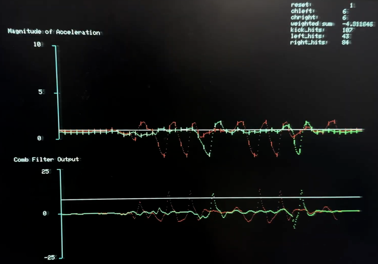
Figure 4: A visualization of the graphing VGA display, with red data corresponding to the right hand and green data corresponding to the left hand. The top graph is the z-acceleration data, with a horizontal white line placed on to illustrate where the equilibrium point is. The bottom graph illustrates the comb filter output for either hand, where the white line is the threshold that the comb filter must output to be registered as a hit.
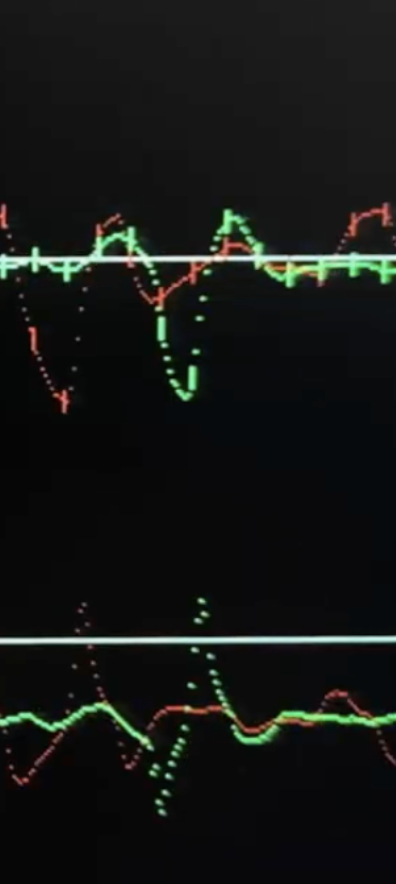
Figure 5: A close up of the shape of acceleration data that causes the sum that is outputted from the comb filter to surpass the threshold.
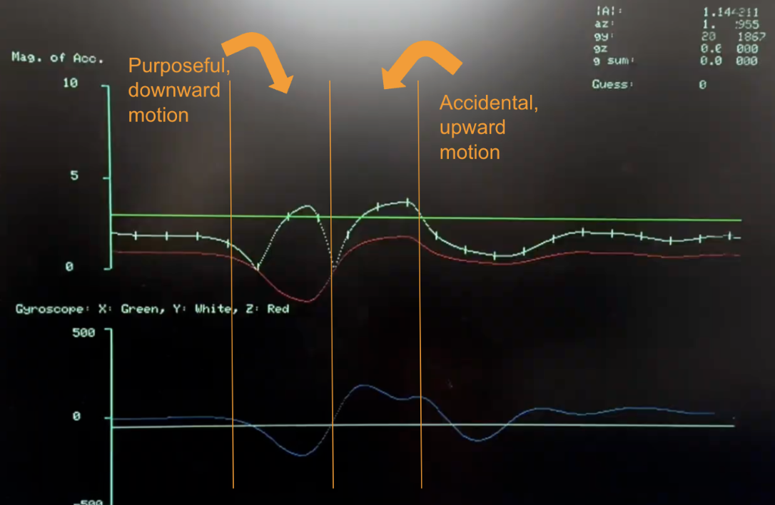
Figure 6: On the top graph, there is the raw z-acceleration data in red, a scaled magnitude of the z-acceleration in white, and a green horizontal line that was used as reference to an acceleration threshold above which a strike would be considered valid. On the bottom graph, the y-gyroscope data is being plotted in blue, in real time and synced with the acceleration data, with a reference line horizontally in white. This figure is of a simple, valid strike.
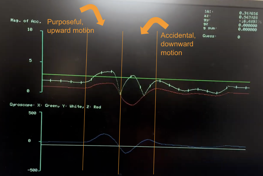
Figure 7: On the top graph, there is the raw z-acceleration data in red, a scaled magnitude of the z-acceleration in white, and a green horizontal line that was used as reference to an acceleration threshold above which a strike would be considered valid. On the bottom graph, the y-gyroscope data is being plotted in blue, in real time and synced with the acceleration data, with a reference line horizontally in white. This figure is of a simple, invalid strike.
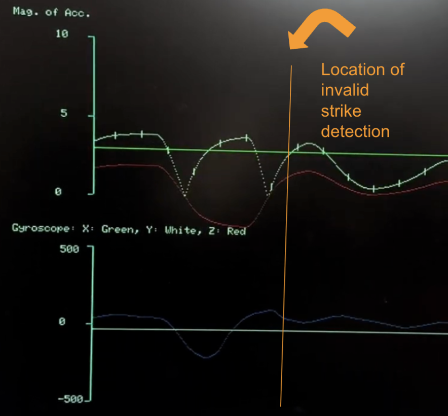
Figure 8: An example of an invalid strike that would have been registered as a valid strike with the original method of strike detection. The last upwards motion is not intentional by the user, and it is therefore wrongly registered by the original program as a strike.
Figure 9: A schematic of our final user input circuit, including the comparator circuit used to amplify the output of the footpedal.
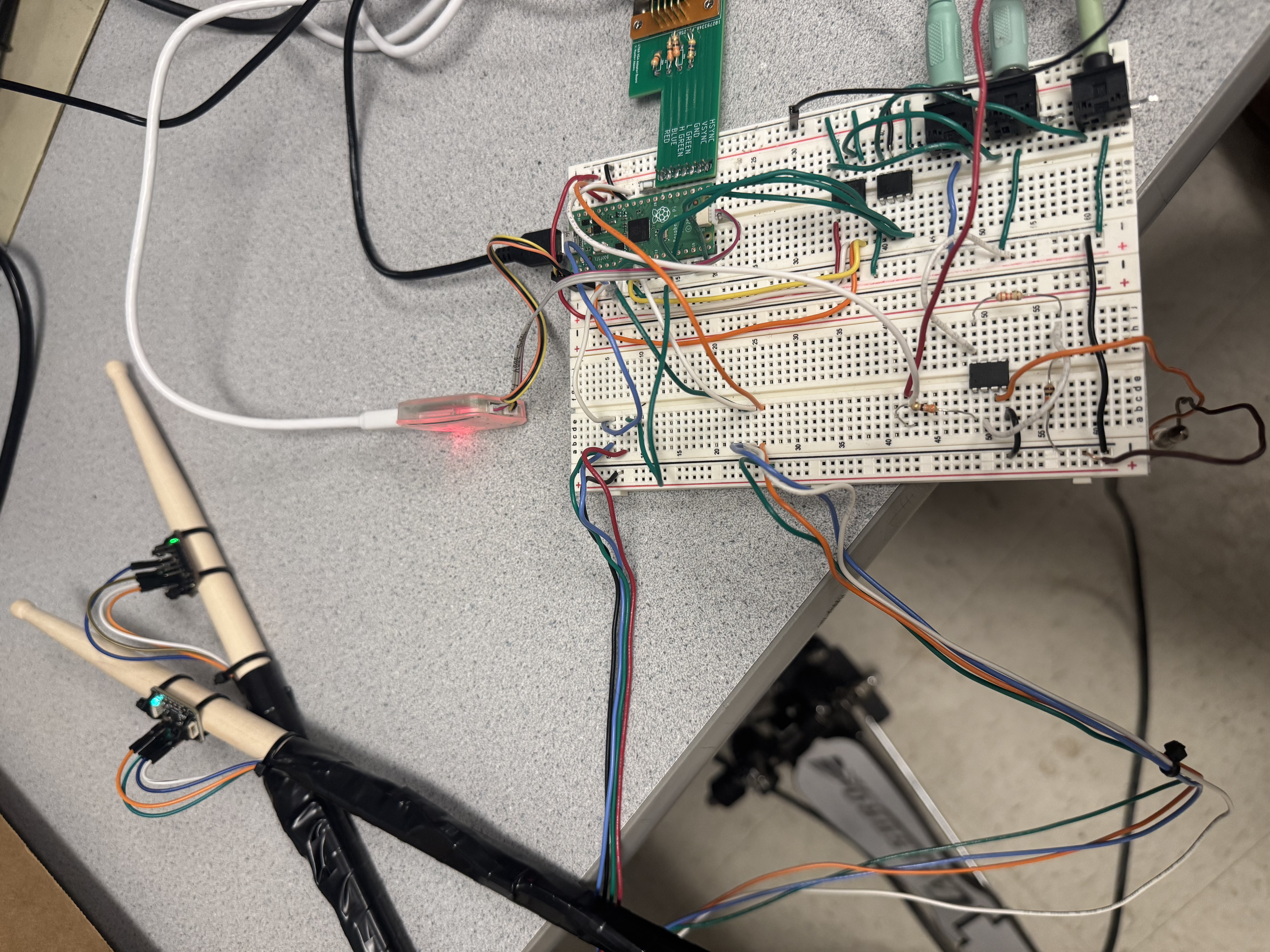
Figure 10: A photograph of our final circuit design.
Users can comfortably achieve about 200~220 BPM with our system, which may not seem very fast, but for the untrained drummer it can be quite a challenge to play the snare, hi-hat, and bass at this base frequency all at the same time. Beyond about 250 BPM, the accuracy of the comb filter begins to decline because the drumsticks are moving so quickly that the desired strike shape that is embedded within the comb filter is squished together. This means that the filter can no longer exaggerate the various peaks of the strike, and it will have a harder time registering valid strikes.
Our design was relatively safe. All the equipment was low power, so users were not in danger from electrical shock. The only safety concerns that might occur with DigiDrum is that a user could hit themselves with a drumstick on accident, or they could have the speakers on too high and playing the drumset would therefore be very loud. However, in order to give the user the adaptable system possible, in terms of both motion and audio, we decided to not constrain these and let the user use their best judgement.
If someone is able to hold two drumsticks and twitch their foot up and down, then they will find that our system is very easy to use. It does not require much dexterity nor musical talent to use DigiDrum, and this was part of our goal. Even if someone can’t play with both hands or use their foot, the system can be adapted so that multiple sounds could be played with one hand depending on the orientation of the drumstick. The threshold for how hard the user has to move the drumstick for it to be registered as a strike can also be increased or decreased, so a user may tune it to their own strengths and abilities. Additionally, using real drum samples makes the kit sound authentic!
This ease of usage, however, does not guarantee that what noise the user makes will sound musical! As we found out when testing the system, it can be hard to play the drums well, but that is part of the fun.
Our system generally behaved how we originally wanted it to. It was responsive to the user’s actions, the data for all of the sounds was able to be stored on the RP2040, and it was relatively easy to play with upon completing DigiDrum.
However, we did face many setbacks that pushed back our timeline. We had a large issue with determining how to register a valid drum hit and following that we had some difficulty ensuring that the I2C devices never caused the program to hang. We eventually solved both of these issues, but this took time and energy, so we weren’t able to focus as much on the game aspect of DigiDrum as we would have liked to.
If we were to do the project again, it would be wise to first get a prototype that works most of the time, and then go back and try to make it work all of the time. If we had adopted this mindset from earlier on, we could have devoted more resources to developing the other aspects of DigiDrum that we would have liked to have seen in our final product. The main idea for these additions include adding more instruments to the system so that it can resemble a full fledged drumset, which is something that can be pursued in the future.
The group approves this report for inclusion on the course website.
The group approves the video for inclusion on the course youtube channel.
//**
* V. Hunter Adams (vha3@cornell.edu)
*
* This demonstration utilizes the MPU6050.
* It gathers raw accelerometer/gyro measurements, scales
* them, and plots them to the VGA display. The top plot
* shows gyro measurements, bottom plot shows accelerometer
* measurements.
*
* HARDWARE CONNECTIONS
* - GPIO 16 ---> VGA Hsync
* - GPIO 17 ---> VGA Vsync
* - GPIO 18 ---> 470 ohm resistor ---> VGA Green
* - GPIO 19 ---> 330 ohm resistor ---> VGA Green
* - GPIO 20 ---> 330 ohm resistor ---> VGA Blue
* - GPIO 21 ---> 330 ohm resistor ---> VGA Red
* - RP2040 GND ---> VGA GND
*
* IMU 1 CONNECTIONS
* - GPIO 8 ---> MPU6050 SDA
* - GPIO 9 ---> MPU6050 SCL
* - 3.3v ---> MPU6050 VCC
* - RP2040 GND ---> MPU6050 GND
* IMU 2 CONNECTIONS
* - GPIO 10 ---> MPU6050 SDA
* - GPIO 11 ---> MPU6050 SCL
* - 3.3v ---> MPU6050 VCC
* - RP2040 GND ---> MPU6050 GND
*
* PEDAL CONNECTIONS
* GPIO 27 ---> 330 ohm resistor ---> MCP6242 VOUTA
* PEDAL OUTPUT ---> MCP6242 VINA+
* PEDAL GND ---> RP2040 GND
* 3.3V ---> MCP6242 VDD
* 0.5V ---> MCP6242 VINA-
* RP2040 GND ---> MCP6242 VSS
*
*/
// Include standard libraries
#include
#include
#include
#include
// Include PICO libraries
#include "pico/stdlib.h"
#include "pico/multicore.h"
// Include hardware libraries
#include "hardware/pwm.h"
#include "hardware/dma.h"
#include "hardware/irq.h"
#include "hardware/adc.h"
#include "hardware/pio.h"
#include "hardware/i2c.h"
#include "hardware/clocks.h"
#include "hardware/spi.h"
// Include custom libraries
#include "vga16_graphics_v2.h"
#include "mpu6050.h"
#include "mpu6050_CHANNEL_1.h"
#include "pt_cornell_rp2040_v1_4.h"
#include "hihat.h"
#include "kick_new.h"
#include "snare_B.h"
#include "NeverGonnaGiveYouUpTab.h"
#include "drumkit_bg.h"
#define _USE_MATH_DEFINES
// character array
char screentext[40];
char DutyCycle[40];
char AngleText[40];
#define LED 25
#define BUTTON_INPUT 15 // GPIO 15, PIN 20, normally high, pulled low when pushed
#define PEDAL_INPUT 27 // GPIO 27, PIN 32, pedal pin intialization
static int STATE = 0; // Records the state of the debouncing FSM
int threshold = 1 ; // draw speed for graphing
// Some macros for max/min/abs
#define min(a,b) ((a0) ? a:-a)
// semaphores
static struct pt_sem playback_semaphore ;
static struct pt_sem vga_display_semaphore ;
// Low-level alarm infrastructure we'll be using
#define ALARM_NUM 0
#define ALARM_IRQ TIMER_IRQ_0
#define DRUM_DELAY 1500 // in microseconds --> 0.0015 second delay
//GPIO for drum the ISR
#define ISR_GPIO 6
////////////////////////// MPU6050 //////////////////////////////
// Arrays in which raw measurements will be stored
fix15 acceleration_right[3], gyro_right[3];
// Angle variables for complimentary filter
fix15 accel_z_r = float2fix15(0.0);
// Arrays in which raw measurements will be stored
fix15 acceleration_left[3], gyro_left[3];
// Angle variables for complimentary filter
fix15 accel_z_l = float2fix15(0.0);
////////////////////////// DRUM HIT LOGIC STUFF //////////////////////////////
#define RING_BUFFER_LENGTH 256
fix15 acc_threshold = int2fix15(8);
// Right Hand
fix15 right_accel_z_data[RING_BUFFER_LENGTH];
fix15 right_weighted_sum = int2fix15(0);
int right_hits = 0;
int right_hit_triggered = 0;
int right_list_counter = 0;
// Left Hand
fix15 left_accel_z_data[RING_BUFFER_LENGTH];
fix15 left_weighted_sum = int2fix15(0);
int left_hits = 0;
int left_hit_triggered = 0;
int left_list_counter = 0;
int kick_hits = 0;
////////////////////////// STATE LOGIC STUFF //////////////////////////////
int screen_to_draw = 0; // 1 means the game display
int clear_screen = 0; // Used when transitioning from one display to the other
int redraw_all_drums = 1;
int previously_game = 0;
////////////////////////// DRUM SETUP STUFF //////////////////////////////
short drum_set_color = WHITE;
///////////// BASS DRUM ///////////////
short bass_color = RED;
// Drum
short bass_x = 470;
short bass_y = 240;
short bass_r_outer = 100;
short bass_r_inner = 90;
// Right Leg
short r_bottom_x0 = 545;
short r_bottom_y0 = 175;
short r_bottom_x1 = 570;
short r_bottom_y1 = 165;
short r_top_x0 = 535;
short r_top_y0 = 165;
short r_top_x1 = 570;
short r_top_y1 = 152;
// Left Leg
short l_bottom_x0 = 545;
short l_bottom_y0 = 310;
short l_bottom_x1 = 570;
short l_bottom_y1 = 320;
short l_top_x0 = 535;
short l_top_y0 = 315;
short l_top_x1 = 570;
short l_top_y1 = 328;
///////////// SNARE DRUM ///////////////
short snare_color = GREEN;
// Drum
const short snare_x_inner = 345;
const short snare_y_inner = 325;
const short snare_w_inner = 30;
const short snare_h_inner = 100;
const short snare_r_inner = 17;
const short snare_x_outer = snare_x_inner - 3;
const short snare_y_outer = snare_y_inner - 3;
const short snare_w_outer = snare_w_inner + 5;
const short snare_h_outer = snare_h_inner + 5;
const short snare_r_outer = snare_r_inner + 1;
// Frame
const short frame_x = snare_x_inner + 40;
const short frame_y = snare_y_inner - 3;
const short frame_w = snare_w_outer;
const short frame_h = snare_h_outer;
const short frame_r = snare_r_outer;
short block1_x = frame_x;
short block1_y = frame_y;
short block1_w = (int) (frame_w/2);
short block1_h = frame_h;
// Stand
const short s_bottom_x0 = frame_x+frame_w;
const short s_bottom_y0 = frame_y+frame_h/2;
const short s_bottom_x1 = s_bottom_x0 + 150;
const short s_bottom_y1 = s_bottom_y0;
const short s_top_x0 = frame_x+frame_w;
const short s_top_y0 = frame_y+frame_h/2-8;
const short s_top_x1 = s_top_x0 + 150;
const short s_top_y1 = s_top_y0;
const short s_x = s_top_x1 - 10;
const short s_y = s_top_y1 - 25;
short s_w = 20;
const short s_h = 60;
short s_r = 8;
short block3_x = s_x - 1;
short block3_y = s_y + s_h/2 - (s_bottom_y1 - s_top_y1)/2;
short block3_w = 5;
short block3_h = (s_bottom_y1 - s_top_y1) - 1;
///////////// HIGH HAT ///////////////
short high_hat_color = BLUE;
// High Hat
const short high_hat_x = 290;
const short high_hat_y = 70;
const short high_hat_w = 15;
const short high_hat_h = 90;
const short high_hat_r = 9;
// Stand
const short c_bottom_x0 = high_hat_x+high_hat_w;
const short c_bottom_y0 = high_hat_y+(high_hat_h/2)-3;
const short c_bottom_x1 = c_bottom_x0 + 260;
const short c_bottom_y1 = c_bottom_y0;
const short c_top_x0 = c_bottom_x0;
const short c_top_y0 = high_hat_y+(high_hat_h/2)+3;
const short c_top_x1 = c_bottom_x1;
const short c_top_y1 = c_top_y0;
const short c_x = c_top_x1 - 10;
const short c_y = c_top_y1 - 30;
short c_w = 20;
const short c_h = 60;
short c_r = 8;
short block4_x = c_x - 1;
short block4_y = c_y + c_h/2 - (c_top_y1 - c_bottom_y1) + 1;
short block4_w = 5;
short block4_h = (c_top_y1 - c_bottom_y1) - 1;
////////////////////////// NOISES //////////////////////////////
int ctrl_chan_kick;
int ctrl_chan_hh;
int ctrl_chan_snare;
//SPI configurations
#define PIN_CS 5 //pin 7 CSn
#define PIN_SCK 2 //pin 4 SCK
#define PIN_MOSI 7 //pin 10 TX
#define SPI_PORT spi0
#define PIN_CS1 13 //pin 17 CSn
#define PIN_SCK1 14 //pin 19 SCK
#define PIN_MOSI1 11 //pin 25 TX
#define SPI_PORT1 spi1
#define hihat_size 5774
// Table of values to be sent to DAC for the hihat
unsigned short DAC_data_hihat[hihat_size] ;
// Pointer to the address of the DAC data table for the hihat
static unsigned short * address_pointer_for_hihat = &DAC_data_hihat[0] ;
#define kick_size 24039
// Table of values to be sent to DAC for the hihat
unsigned short DAC_data_kick[kick_size] ;
// Pointer to the address of the DAC data table for the hihat
static unsigned short * address_pointer_for_kick = &DAC_data_kick[0] ;
#define snare_size 8848
// Table of values to be sent to DAC for the hihat
unsigned short DAC_data_snare[snare_size] ;
// Pointer to the address of the DAC data table for the hihat
static unsigned short * address_pointer_for_snare = &DAC_data_snare[0] ;
////////////////////////// I2C POWER STUFF //////////////////////////////
#define MPU_RIGHT_POWER 28 //pin 34
#define MPU_LEFT_POWER 4 //pin 6
////////////////////////// GAME STUFF //////////////////////////////
#define GAME_LINE 245
#define hitBottom(b) (b>int2fix15(GAME_LINE))
fix15 velocity_hihat = float2fix15(15);
fix15 velocity_snare = float2fix15(5);
fix15 velocity_kick = float2fix15(5);
typedef struct {
fix15 x;
fix15 y;
fix15 vx;
char note;
} Ball;
#define NUMBER_OF_BALLS_CORE0 10
Ball listOfBallsCore0[NUMBER_OF_BALLS_CORE0];
int ball_radius = 5;
int half_window_width = 8;
volatile int trigger_bass = 0;
volatile int trigger_high_hat = 0;
volatile int trigger_snare = 0;
int bass_triggered = 0;
int high_hat_triggered = 0;
int snare_triggered = 0;
int clear_bass = 0;
int clear_high_hat = 0;
int clear_snare = 0;
int color_duration = 100;
int resetting = 0;
// ===== Metronome config =====
#define ANIM_STEP_US 20000 // matches PT_YIELD_usec(20000)
#define METRO_DISTANCE_PX (GAME_LINE) // x travels from 0 -> GAME_LINE per beat
volatile int bpm_hihat = 120;
volatile int bpm_snare = 60;
volatile int bpm_kick = 60;
static inline int clamp_int(int v, int lo, int hi) {
if (v < lo) return lo;
if (v > hi) return hi;
return v;
}
// Convert BPM to "pixels per animation tick"
static void update_metro_velocities(void) {
int bh = clamp_int(bpm_hihat, 10, 400);
int bs = clamp_int(bpm_snare, 10, 400);
int bk = clamp_int(bpm_kick, 10, 400);
// ticks_per_beat = (60s/bpm) / 0.02s = 3000/bpm
// vx = distance / ticks_per_beat = distance * bpm / 3000 [pixels per tick]
velocity_hihat = float2fix15(((float)METRO_DISTANCE_PX * (float)bh) / 3000.0f);
velocity_snare = float2fix15(((float)METRO_DISTANCE_PX * (float)bs) / 3000.0f);
velocity_kick = float2fix15(((float)METRO_DISTANCE_PX * (float)bk) / 3000.0f);
}
int counter = 0;
int done_reset = 0;
void system_reset() // Turns the IMUs off and then back on, reinitializing them
{
gpio_init(MPU_RIGHT_POWER);
gpio_set_dir(MPU_RIGHT_POWER, GPIO_OUT);
gpio_put(MPU_RIGHT_POWER, 0) ;
gpio_init(MPU_LEFT_POWER);
gpio_set_dir(MPU_LEFT_POWER, GPIO_OUT);
gpio_put(MPU_LEFT_POWER, 0) ;
gpio_put(MPU_RIGHT_POWER, 1) ;
gpio_put(MPU_LEFT_POWER, 1) ;
i2c_init(I2C_CHAN, I2C_BAUD_RATE) ;
gpio_set_function(SDA_PIN, GPIO_FUNC_I2C) ;
gpio_set_function(SCL_PIN, GPIO_FUNC_I2C) ;
i2c_init(I2C_CHAN_CHANNEL_1, I2C_BAUD_RATE_CHANNEL_1) ;
gpio_set_function(SDA_PIN_CHANNEL_1, GPIO_FUNC_I2C) ;
gpio_set_function(SCL_PIN_CHANNEL_1, GPIO_FUNC_I2C) ;
// MPU6050 initialization
mpu6050_reset();
mpu6050_reset_CHANNEL_1();
mpu6050_read_raw(acceleration_right, gyro_right);
mpu6050_read_raw_CHANNEL_1(acceleration_left, gyro_left);
}
int chright;
int chleft;
// Interrupt service routine that checks for valid drum strikes
void drum_check_irq() {
// Assert a GPIO when we enter the interrupt
gpio_put(ISR_GPIO, 1) ;
// Clear the alarm irq
hw_clear_bits(&timer_hw->intr, 1u << ALARM_NUM);
// Reset the alarm register
timer_hw->alarm[ALARM_NUM] = timer_hw->timerawl + DRUM_DELAY ;
// Read the IMU
// NOTE! This is in 15.16 fixed point. Accel in g's, gyro in deg/s
// If you want these values in floating point, call fix2float15() on
// the raw measurements.
chright = mpu6050_read_raw(acceleration_right, gyro_right);
if(chright<0){
system_reset();
chright=9;
chleft=9;
}
chleft= mpu6050_read_raw_CHANNEL_1(acceleration_left, gyro_left);
if(chleft<0){
system_reset();
chleft=9;
chright=9;
}
// Low pass accelerometer data, right hand
accel_z_r = accel_z_r + ((acceleration_right[2] - accel_z_r)>>4) ;
// Adding the data to the right hand's ring buffer
right_accel_z_data[(right_list_counter)&0xFF] = accel_z_r ;
// The combfilter output for the right hand
right_weighted_sum = multfix15(int2fix15(-12), right_accel_z_data[(right_list_counter-15)&0xFF]) + multfix15(int2fix15(12), right_accel_z_data[(right_list_counter-10)&0xFF]) + multfix15(int2fix15(-6), right_accel_z_data[(right_list_counter-5)&0xFF]) + multfix15(int2fix15(6), right_accel_z_data[(right_list_counter)&0xFF]);
// Low pass accelerometer data, left hand
accel_z_l = accel_z_l + ((acceleration_left[2] - accel_z_l)>>4) ;
// Adding the data to the left hand's ring buffer
left_accel_z_data[(left_list_counter)&0xFF] = accel_z_l ;
// The combfilter output for the right hand
left_weighted_sum = multfix15(int2fix15(-12), left_accel_z_data[(left_list_counter-15)&0xFF]) + multfix15(int2fix15(12), left_accel_z_data[(left_list_counter-10)&0xFF]) + multfix15(int2fix15(-6), left_accel_z_data[(left_list_counter-5)&0xFF]) + multfix15(int2fix15(6), left_accel_z_data[(left_list_counter)&0xFF]);
// Right hand triggering check, if triggered DMA channel send hi-hat noise to DAC
if ((right_weighted_sum >= acc_threshold) && (!right_hit_triggered)){
right_hits = right_hits + 1;
right_hit_triggered = 1;
trigger_high_hat = 1;
dma_start_channel_mask(1u << ctrl_chan_hh);
if(chright<0){
system_reset();
}
}
// If the right hand previously made a strike, wait for the hand to no longer have a comb filter output that is above the threshold
if (right_hit_triggered){
if (right_weighted_sum < acc_threshold){
right_hit_triggered = 0;
trigger_high_hat = 0;
}
}
// The same thing but for the left hand
if ((left_weighted_sum >= acc_threshold) && (!left_hit_triggered)){
left_hits = left_hits + 1;
left_hit_triggered = 1;
trigger_snare = 1;
dma_start_channel_mask(1u << ctrl_chan_snare);
if(chleft<0){
system_reset();
}
}
if (left_hit_triggered){
if (left_weighted_sum < acc_threshold){
left_hit_triggered = 0;
trigger_snare = 0;
}
}
right_list_counter = right_list_counter + 1 ;
left_list_counter = left_list_counter + 1 ;
if(gpio_get(PEDAL_INPUT)){
kick_hits = kick_hits + 1;
trigger_bass = 1;
dma_start_channel_mask(1u << ctrl_chan_kick) ;
}
counter = counter + 1;
// Signal VGA to draw
//change to sdk
PT_SEM_SIGNAL(pt, &vga_display_semaphore);
// De-assert the GPIO when we leave the interrupt
gpio_put(ISR_GPIO, 0) ;
}
void spawnBoid(fix15* x, fix15* y, fix15* vx, char note)
{
*y = int2fix15(high_hat_y + (high_hat_h/2)) ;
*x = int2fix15(0) ;
*vx = velocity_hihat ;
note = note;
}
void spawnMetroBall(Ball* b, int instrument)
{
b->x = int2fix15(0);
if (instrument == 0) { // hi-hat
b->y = int2fix15(high_hat_y + (high_hat_h/2));
b->vx = velocity_hihat;
} else if (instrument == 1) { // kick
b->y = int2fix15(bass_y);
b->vx = velocity_kick;
} else { // snare (instrument == 2)
b->y = int2fix15(snare_y_inner + (snare_h_inner/2));
b->vx = velocity_snare;
}
b->note = instrument;
}
void indicator_physics(fix15* x, fix15* y, fix15* vx, int instrument)
{
// erase previous ball
drawCircle(fix2int15(*x), fix2int15(*y), ball_radius, BLACK);
// ALWAYS use latest bpm-derived velocity
if (instrument == 0) *vx = velocity_hihat;
else if (instrument == 1) *vx = velocity_kick;
else *vx = velocity_snare;
// advance
*x = *x + *vx;
// if crossed the line, fire + reset for next beat
if (hitBottom(*x)) {
*x = int2fix15(0);
if (instrument == 0) {
*y = int2fix15(high_hat_y + (high_hat_h/2));
} else if (instrument == 1) {
*y = int2fix15(bass_y);
} else {
*y = int2fix15(snare_y_inner + (snare_h_inner/2));
}
}
// redraw at new position
if (instrument == 0) drawCircle(fix2int15(*x), fix2int15(*y), ball_radius, high_hat_color);
else if (instrument == 1) drawCircle(fix2int15(*x), fix2int15(*y), ball_radius, bass_color);
else if (instrument == 2) drawCircle(fix2int15(*x), fix2int15(*y), ball_radius, snare_color);
}
// Animation on core 0
static PT_THREAD (protothread_anim(struct pt *pt))
{
// Mark beginning of thread
PT_BEGIN(pt);
update_metro_velocities();
spawnMetroBall(&listOfBallsCore0[0], 0);
spawnMetroBall(&listOfBallsCore0[1], 1);
spawnMetroBall(&listOfBallsCore0[2], 2);
for (int i = 0; i < NUMBER_OF_BALLS_CORE0; i = i + 1){
char a='d';
spawnBoid(&listOfBallsCore0[i].x, &listOfBallsCore0[i].y, &listOfBallsCore0[i].vx, a) ;
}
int notification_drawn = 0;
while(1) {
if (screen_to_draw){
for (int i = 0; i < 3; i++) {
indicator_physics(&listOfBallsCore0[i].x,
&listOfBallsCore0[i].y,
&listOfBallsCore0[i].vx,
i);
}
}
PT_YIELD_usec(20000) ; // run every 0.02 seconds
// NEVER exit while
} // END WHILE(1)
PT_END(pt);
} // animation thread
// Thread that draws to VGA display
static PT_THREAD (protothread_vga_display(struct pt *pt))
{
// Indicate start of thread
PT_BEGIN(pt) ;
// We will start drawing at column 81
static int xcoord = 81 ;
// Rescale the measurements for display
static float OldRange = 500. ; // (+/- 250)
static float NewRange = 150. ; // (looks nice on VGA)
static float OldMin = -250. ;
static float OldMax = 250. ;
// Control rate of drawing
static int throttle ;
// Draw the static aspects of the display
setTextSize(1) ;
setTextColor(WHITE);
while (true) {
// Wait on semaphore
PT_SEM_WAIT(pt, &vga_display_semaphore);
if (clear_screen){
clearLowFrame(0, BLACK);
clear_screen = 0;
}
if (screen_to_draw){
if (redraw_all_drums){
// Snare
drawRoundRect(snare_x_inner, snare_y_inner, snare_w_inner, snare_h_inner, snare_r_inner, drum_set_color) ;
drawRoundRect(snare_x_outer, snare_y_outer, snare_w_outer, snare_h_outer, snare_r_outer, drum_set_color) ;
drawRoundRect(frame_x, frame_y, frame_w, frame_h, frame_r, drum_set_color) ;
fillRect(block1_x, block1_y, block1_w, block1_h, BLACK) ;
drawLine(frame_x+frame_w/2, frame_y, snare_x_outer + snare_w_outer/2, snare_y_outer, drum_set_color) ;
drawLine(frame_x+frame_w/2, frame_y+frame_h, snare_x_outer + snare_w_outer/2, snare_y_outer + frame_h, drum_set_color) ;
drawLine(s_bottom_x0, s_bottom_y0, s_bottom_x1, s_bottom_y1, drum_set_color) ;
drawLine(s_top_x0, s_top_y0, s_top_x1, s_top_y1, drum_set_color) ;
drawRoundRect(s_x, s_y, s_w, s_h, s_r, drum_set_color) ;
fillRect(block3_x, block3_y, block3_w, block3_h, BLACK) ;
// Bass
drawCircle(bass_x, bass_y, bass_r_outer, drum_set_color) ;
drawCircle(bass_x, bass_y, bass_r_inner, drum_set_color) ;
drawLine(r_bottom_x0, r_bottom_y0, r_bottom_x1, r_bottom_y1, drum_set_color) ;
drawLine(r_top_x0, r_top_y0, r_top_x1, r_top_y1, drum_set_color) ;
drawLine(r_bottom_x1, r_bottom_y1, r_top_x1, r_top_y1, drum_set_color) ;
drawLine(l_bottom_x0, l_bottom_y0, l_bottom_x1, l_bottom_y1, drum_set_color) ;
drawLine(l_top_x0, l_top_y0, l_top_x1, l_top_y1, drum_set_color) ;
drawLine(l_bottom_x1, l_bottom_y1, l_top_x1, l_top_y1, drum_set_color) ;
// High Hat
drawRoundRect(high_hat_x, high_hat_y, high_hat_w, high_hat_h, high_hat_r, drum_set_color) ;
drawLine(c_bottom_x0, c_bottom_y0, c_bottom_x1, c_bottom_y1, drum_set_color) ;
drawLine(c_top_x0, c_top_y0, c_top_x1, c_top_y1, drum_set_color) ;
drawRoundRect(c_x, c_y, c_w, c_h, c_r, drum_set_color) ;
fillRect(block4_x, block4_y, block4_w, block4_h, BLACK) ;
redraw_all_drums = 0;
}
drawVLine(GAME_LINE-half_window_width-3, 0, 480, CYAN );
drawVLine(GAME_LINE-half_window_width-2, 0, 480, CYAN );
drawVLine(GAME_LINE-half_window_width-1, 0, 480, CYAN );
drawVLine(GAME_LINE+half_window_width+3, 0, 480, CYAN );
drawVLine(GAME_LINE+half_window_width+2, 0, 480, CYAN );
drawVLine(GAME_LINE+half_window_width+1, 0, 480, CYAN );
if (trigger_high_hat){
fillRoundRect(high_hat_x+3, high_hat_y+5,
high_hat_w-5, high_hat_h-10,
high_hat_r-5, high_hat_color);
trigger_high_hat = 0;
clear_high_hat = color_duration;
} else {
if (clear_high_hat > 0){
clear_high_hat--;
} else {
fillRoundRect(high_hat_x+3, high_hat_y+5,
high_hat_w-5, high_hat_h-10,
high_hat_r-5, BLACK);
}
}
if (trigger_snare){
fillRoundRect(snare_x_inner+3, snare_y_inner+5, snare_w_inner-5, snare_h_inner-10, snare_r_inner-5, snare_color);
trigger_snare = 0;
clear_snare = color_duration;
} else {
if (clear_snare > 0){
clear_snare = clear_snare - 1;
} else {
fillRoundRect(snare_x_inner+3, snare_y_inner+5, snare_w_inner-5, snare_h_inner-10, snare_r_inner-5, BLACK);
}
}
if (trigger_bass){
fillCircle(bass_x, bass_y, 25, bass_color) ;
trigger_bass = 0;
clear_bass = color_duration;
} else {
if (clear_bass > 0){
clear_bass = clear_bass - 1;
} else {
fillCircle(bass_x, bass_y, 25, BLACK) ;
}
}
} else {
redraw_all_drums = 1 ;
// Draw bottom plot (accelerometer)
drawHLine(75, 430, 5, CYAN) ;
drawHLine(75, 355, 5, CYAN) ;
drawHLine(75, 280, 5, CYAN) ;
drawVLine(80, 280, 150, CYAN) ;
// Draw top plot (gyroscope)
drawHLine(75, 230, 5, CYAN) ;
drawHLine(75, 155, 5, CYAN) ;
drawHLine(75, 80, 5, CYAN) ;
drawVLine(80, 80, 150, CYAN) ;
// Increment drawspeed controller
throttle += 1 ;
// If the controller has exceeded a threshold, draw
if (throttle >= threshold) {
// Zero drawspeed controller
throttle = 0 ;
// Erase a column
drawVLine(xcoord, 0, 480, BLACK) ;
// Draw the nominal z-acceleration value when hodling the drumstick in the proper orientation
drawPixel(xcoord, 230 - (int)(NewRange*((float)(((1-5)*50)-OldMin)/OldRange)), WHITE) ;
// Draw the ouput of the low passed z-accelerometer data
drawPixel(xcoord, 230 - (int)(NewRange*((float)(((fix2float15(accel_z_r)-5)*50)-OldMin)/OldRange)), RED) ;
// Draws a tick mark every 25 drawing times on the accelerometer data
if (xcoord%10 == 0){
drawPixel(xcoord, 230 - (int)(NewRange*((float)(((fix2float15(accel_z_r)-5)*50)-OldMin)/OldRange)) -1, RED) ;
drawPixel(xcoord, 230 - (int)(NewRange*((float)(((fix2float15(accel_z_r)-5)*50)-OldMin)/OldRange)) -2, RED) ;
drawPixel(xcoord, 230 - (int)(NewRange*((float)(((fix2float15(accel_z_r)-5)*50)-OldMin)/OldRange)) -3, RED) ;
drawPixel(xcoord, 230 - (int)(NewRange*((float)(((fix2float15(accel_z_r)-5)*50)-OldMin)/OldRange)) +1, RED) ;
drawPixel(xcoord, 230 - (int)(NewRange*((float)(((fix2float15(accel_z_r)-5)*50)-OldMin)/OldRange)) +2, RED) ;
drawPixel(xcoord, 230 - (int)(NewRange*((float)(((fix2float15(accel_z_r)-5)*50)-OldMin)/OldRange)) +3, RED) ;
}
// Draw the ouput of the low passed z-accelerometer data
drawPixel(xcoord, 230 - (int)(NewRange*((float)(((fix2float15(accel_z_l)-5)*50)-OldMin)/OldRange)), GREEN) ;
// Draws a tick mark every 25 drawing times on the accelerometer data
if (xcoord%10 == 0){
drawPixel(xcoord, 230 - (int)(NewRange*((float)(((fix2float15(accel_z_l)-5)*50)-OldMin)/OldRange)) -1, GREEN) ;
drawPixel(xcoord, 230 - (int)(NewRange*((float)(((fix2float15(accel_z_l)-5)*50)-OldMin)/OldRange)) -2, GREEN) ;
drawPixel(xcoord, 230 - (int)(NewRange*((float)(((fix2float15(accel_z_l)-5)*50)-OldMin)/OldRange)) -3, GREEN) ;
drawPixel(xcoord, 230 - (int)(NewRange*((float)(((fix2float15(accel_z_l)-5)*50)-OldMin)/OldRange)) +1, GREEN) ;
drawPixel(xcoord, 230 - (int)(NewRange*((float)(((fix2float15(accel_z_l)-5)*50)-OldMin)/OldRange)) +2, GREEN) ;
drawPixel(xcoord, 230 - (int)(NewRange*((float)(((fix2float15(accel_z_l)-5)*50)-OldMin)/OldRange)) +3, GREEN) ;
}
// Draws the sum of the "drum hit likely" parameter
drawPixel(xcoord, 430 - (int)(NewRange*((float)(((fix2float15(right_weighted_sum))*10)-OldMin)/OldRange)), RED) ;
// Draws the sum of the "drum hit likely" parameter
drawPixel(xcoord, 430 - (int)(NewRange*((float)(((fix2float15(left_weighted_sum))*10)-OldMin)/OldRange)), GREEN) ;
// Draws the threshold that the "drum hit likely" parameter must surpass to be considered a drumhit
drawPixel(xcoord, 430 - (int)(NewRange*((float)(((fix2float15(acc_threshold))*10)-OldMin)/OldRange)), WHITE) ;
// Update horizontal cursor
if (xcoord < 609) {
xcoord += 1 ;
}
else {
xcoord = 81 ;
}
}
}
}
// Indicate end of thread
PT_END(pt);
}
// User input thread. User can change draw speed
static PT_THREAD (protothread_serial(struct pt *pt))
{
PT_BEGIN(pt) ;
static char classifier ;
static int test_in ;
static float float_in ;
while(1) {
sprintf(pt_serial_out_buffer, "input a command: ");
serial_write ;
// spawn a thread to do the non-blocking serial read
serial_read ;
// convert input string to number
sscanf(pt_serial_in_buffer,"%c", &classifier) ;
// Used to change the speed at which the VGA draws
if (classifier=='t') {
sprintf(pt_serial_out_buffer, "timestep: ");
serial_write ;
serial_read ;
// convert input string to number
sscanf(pt_serial_in_buffer,"%d", &test_in) ;
if (test_in > 0) {
threshold = test_in ;
}
}
// Used to change the speed at which the VGA draws
if (classifier=='g') {
sprintf(pt_serial_out_buffer, "Reset right_hits: ");
serial_write ;
serial_read ;
// convert input string to number
sscanf(pt_serial_in_buffer,"%d", &test_in) ;
if (test_in > 0) {
right_hits = test_in ;
}
}
// Used to change the speed at which the VGA draws
if (classifier=='a') {
sprintf(pt_serial_out_buffer, "acceleration sum threshold: ");
serial_write ;
serial_read ;
// convert input string to number
sscanf(pt_serial_in_buffer,"%d", &test_in) ;
if (test_in > 0) {
acc_threshold = float2fix15(test_in) ;
}
}
// Used to change the BPMs of the metronomes
// High-hat bpm
if (classifier=='h') {
sprintf(pt_serial_out_buffer, "hihat bpm: ");
serial_write;
serial_read;
sscanf(pt_serial_in_buffer, "%d", &test_in);
bpm_hihat = test_in;
update_metro_velocities();
}
// Snare bpm
if (classifier=='s') {
sprintf(pt_serial_out_buffer, "snare bpm: ");
serial_write;
serial_read;
sscanf(pt_serial_in_buffer, "%d", &test_in);
bpm_snare = test_in;
update_metro_velocities();
}
// Kick bpm
if (classifier=='k') {
sprintf(pt_serial_out_buffer, "kick bpm: ");
serial_write;
serial_read;
sscanf(pt_serial_in_buffer, "%d", &test_in);
bpm_kick = test_in;
update_metro_velocities();
}
}
PT_END(pt) ;
}
// Protothread for displaying text on the VGA
static PT_THREAD (protothread_display_values(struct pt *pt))
{
// Mark beginning of thread
PT_BEGIN(pt);
if (!screen_to_draw){
// Display on VGA
char line1[32] = "reset: ";
char line2[32] = "chleft: ";
char line3[32] = "chright: ";
char line4[32] = "weighted sum ";
char line5[32] = "kick_hits: ";
char line6[32] = "left_hits: ";
char line7[32] = "right_hits: ";
char line1new[32];
char line2new[32];
char line3new[32];
char line4new[32];
char line5new[32];
char line6new[32];
char line7new[32];
sprintf(line1new, "%d ", done_reset);
sprintf(line2new, "%d ", chleft);
sprintf(line3new, "%d ", chright);
sprintf(line4new, "%f ", fix2float15(right_weighted_sum));
sprintf(line5new, "%d ", kick_hits);
sprintf(line6new, "%d ", left_hits);
sprintf(line7new, "%d ", right_hits);
strcat(line1, line1new);
strcat(line2, line2new);
strcat(line3, line3new);
strcat(line4, line4new);
strcat(line5, line5new);
strcat(line6, line6new);
strcat(line7, line7new);
setTextSize(1);
setTextColor2(WHITE, BLACK);
setCursor(480, 8);
writeString(line1);
setCursor(480, 18);
writeString(line2);
setCursor(480, 28);
writeString(line3);
setCursor(480, 38);
writeString(line4);
setCursor(480, 48);
writeString(line5);
setCursor(480, 58);
writeString(line6);
setCursor(480, 68);
writeString(line7);
setCursor(480, 78);
sprintf(screentext, "0") ;
setCursor(50, 350) ;
writeString(screentext) ;
sprintf(screentext, "25") ;
setCursor(50, 280) ;
writeString(screentext) ;
sprintf(screentext, "-25") ;
setCursor(50, 425) ;
writeString(screentext) ;
sprintf(screentext, "5") ;
setCursor(50, 150) ;
writeString(screentext) ;
sprintf(screentext, "10") ;
setCursor(45, 75) ;
writeString(screentext) ;
sprintf(screentext, "0") ;
setCursor(45, 225) ;
writeString(screentext) ;
sprintf(screentext, "Magnitude of Acceleration") ;
setCursor(5, 55) ;
writeString(screentext) ;
sprintf(screentext, "Comb Filter Output") ;
setCursor(5, 260) ;
writeString(screentext) ;
}
PT_END(pt);
} // display values thread
// Entry point for core 1
void core1_entry() {
////////////////////////////////////////////////////////////////////////
///////////////////////// IRQ CONFIGURATION ////////////////////////////
////////////////////////////////////////////////////////////////////////
gpio_init(MPU_RIGHT_POWER);
gpio_set_dir(MPU_RIGHT_POWER, GPIO_OUT);
gpio_put(MPU_RIGHT_POWER, 0) ;
gpio_init(MPU_LEFT_POWER);
gpio_set_dir(MPU_LEFT_POWER, GPIO_OUT);
gpio_put(MPU_LEFT_POWER, 0) ;
busy_wait_ms(20);
gpio_put(MPU_RIGHT_POWER, 1) ;
gpio_put(MPU_LEFT_POWER, 1) ;
busy_wait_ms(20);
i2c_init(I2C_CHAN, I2C_BAUD_RATE) ;
gpio_set_function(SDA_PIN, GPIO_FUNC_I2C) ;
gpio_set_function(SCL_PIN, GPIO_FUNC_I2C) ;
i2c_init(I2C_CHAN_CHANNEL_1, I2C_BAUD_RATE_CHANNEL_1) ;
gpio_set_function(SDA_PIN_CHANNEL_1, GPIO_FUNC_I2C) ;
gpio_set_function(SCL_PIN_CHANNEL_1, GPIO_FUNC_I2C) ;
busy_wait_ms(20);
// Enable the interrupt for the alarm (we're using Alarm 0)
hw_set_bits(&timer_hw->inte, 1u << ALARM_NUM) ;
// Associate an interrupt handler with the ALARM_IRQ
irq_set_exclusive_handler(ALARM_IRQ, drum_check_irq) ;
// Enable the alarm interrupt
irq_set_enabled(ALARM_IRQ, true) ;
// Write the lower 32 bits of the target time to the alarm register, arming it.
timer_hw->alarm[ALARM_NUM] = timer_hw->timerawl + DRUM_DELAY ;
// Setup the ISR-timing GPIO
gpio_init(ISR_GPIO) ;
gpio_set_dir(ISR_GPIO, GPIO_OUT);
gpio_put(ISR_GPIO, 0) ;
// MPU6050 initialization
mpu6050_reset();
mpu6050_read_raw(acceleration_right, gyro_right);
mpu6050_reset_CHANNEL_1();
mpu6050_read_raw_CHANNEL_1(acceleration_left, gyro_left);
done_reset =1;
}
// UI on core 0
static PT_THREAD (protothread_ui(struct pt *pt))
{
// Mark beginning of thread
PT_BEGIN(pt);
while(1) {
if(chleft<0){
done_reset=0;
multicore_reset_core1();
multicore_launch_core1(core1_entry);
chleft=0;
chright=0;
}
if(chright<0){
multicore_reset_core1();
multicore_launch_core1(core1_entry);
chleft=0;
chright=0;
}
int currButton = gpio_get(BUTTON_INPUT);
switch (STATE){
case 0: // If the button is pressed, move to the state that checks if it is actually pressed
if (!currButton){
STATE = 1; // State that it is actually pressed
} else {
STATE = 0; // The button wasn't actually pressed
}
break;
case 1:
if (!currButton){ // If it is actually pressed, go to State 2 and update the graphics appropriately
STATE = 2;
if (screen_to_draw == 0){
// clearLowFrame(0, BLACK);
screen_to_draw = 1;
clear_screen = 1;
} else {
// clearLowFrame(0, BLACK);
screen_to_draw = 0;
clear_screen = 1;
}
} else { // Else go back to State 0
STATE = 0;
}
break;
case 2:
if (!currButton){ // If the button is still pressed, stay in State 2, don't update the graphics
STATE = 2;
} else { // If the button isn't pressed, check to see if this was an accident
STATE = 3;
}
break;
case 3:
if (!currButton){ // If the button is pressed again, assume it was a mistsake and go back to State 2 without changing the graphics
STATE = 2;
} else { // They stopped pressing the button, go back to the first state
STATE = 0;
}
break;
default:
STATE = 0;
screen_to_draw = 0;
break;
}
PT_YIELD_usec(20000) ; // run every 0.02 seconds
// NEVER exit while
} // END WHILE(1)
PT_END(pt);
} // UI thread
int main() {
// Overclock
set_sys_clock_khz(150000, true) ;
// stdio_init_all() ;
for (int i = 0; i < RING_BUFFER_LENGTH; i = i + 1){
right_accel_z_data[i] = int2fix15(0);
left_accel_z_data[i] = int2fix15(0);
}
// Initialize stdio
stdio_init_all();
////////////////////////////////////////////////////////////////////////
///////////////////////// DMA AND DAC SETUP ////////////////////////////
////////////////////////////////////////////////////////////////////////
// Initialize SPI channel (channel, baud rate set to 20MHz)
spi_init(SPI_PORT, 20000000) ;
spi_init(SPI_PORT1, 20000000) ;
// Format SPI channel (channel, data bits per transfer, polarity, phase, order)
spi_set_format(SPI_PORT, 16, 0, 0, 0);
spi_set_format(SPI_PORT1, 16, 0, 0, 0);
// Map SPI signals to GPIO ports, acts like framed SPI with this CS mapping
// gpio_set_function(PIN_MISO, GPIO_FUNC_SPI);
gpio_set_function(PIN_CS, GPIO_FUNC_SPI) ;
gpio_set_function(PIN_SCK, GPIO_FUNC_SPI);
gpio_set_function(PIN_MOSI, GPIO_FUNC_SPI);
// gpio_set_function(PIN_MISO1, GPIO_FUNC_SPI);
gpio_set_function(PIN_CS1, GPIO_FUNC_SPI) ;
gpio_set_function(PIN_SCK1, GPIO_FUNC_SPI);
gpio_set_function(PIN_MOSI1, GPIO_FUNC_SPI);
// Build table for DAC for hihat
int i ;
for (i=0; i<(hihat_size); i++){
DAC_data_hihat[i] = hihat[i];
}
// Build table for DAC for kick drum
int j ;
for (j=0; j<(kick_size); j++){
DAC_data_kick[j] = kick[j];
}
//Build table for DAC for kick drum
int k ;
for (k=0; k<(snare_size); k++){
DAC_data_snare[k] = snare[k];
}
// Select DMA channels
int data_chan_hh = dma_claim_unused_channel(true);;
ctrl_chan_hh = dma_claim_unused_channel(true);;
int data_chan_snare = dma_claim_unused_channel(true);;
ctrl_chan_snare = dma_claim_unused_channel(true);;
int data_chan_kick = dma_claim_unused_channel(true);;
ctrl_chan_kick = dma_claim_unused_channel(true);;
////////////////////////////////////////////////////////////////////////////////////////////////////
// Setup the control channel high hat
dma_channel_config c = dma_channel_get_default_config(ctrl_chan_hh); // default configs
channel_config_set_transfer_data_size(&c, DMA_SIZE_32); // 32-bit txfers
channel_config_set_read_increment(&c, false); // no read incrementing
channel_config_set_write_increment(&c, false); // no write incrementing
channel_config_set_chain_to(&c, data_chan_hh); // chain to data channel
dma_channel_configure(
ctrl_chan_hh, // Channel to be configured
&c, // The configuration we just created
&dma_hw->ch[data_chan_hh].read_addr, // Write address (data channel read address)
&address_pointer_for_hihat, // Read address (POINTER TO AN ADDRESS)
1, // Number of transfers
false // Don't start immediately
);
// Setup the data channel high hat
dma_channel_config c2 = dma_channel_get_default_config(data_chan_hh); // Default configs
channel_config_set_transfer_data_size(&c2, DMA_SIZE_16); // 16-bit txfers
channel_config_set_read_increment(&c2, true); // yes read incrementing
channel_config_set_write_increment(&c2, false); // no write incrementing
// (X/Y)*sys_clk, where X is the first 16 bytes and Y is the second
// sys_clk is 125 MHz unless changed in code. Configured to ~44 kHz --> sys_clk is now 150 Mhz
dma_timer_set_fraction(0, 0x0017, 0xffff) ; // tried numerator 0x0002
// 0x3b means timer0 (see SDK manual)
channel_config_set_dreq(&c2, 0x3b); // DREQ paced by timer 1
dma_channel_configure(
data_chan_hh, // Channel to be configured
&c2, // The configuration we just created
&spi_get_hw(SPI_PORT)->dr, // write address (SPI data register)
DAC_data_hihat, // The initial read address
hihat_size, // Number of transfers
false // Don't start immediately.
);
////////////////////////////////////////////////////////////////////////////////////////////////////
// Setup the control channel snare
dma_channel_config c12 = dma_channel_get_default_config(ctrl_chan_snare); // default configs
channel_config_set_transfer_data_size(&c12, DMA_SIZE_32); // 32-bit txfers
channel_config_set_read_increment(&c12, false); // no read incrementing
channel_config_set_write_increment(&c12, false); // no write incrementing
channel_config_set_chain_to(&c12, data_chan_snare); // chain to data channel
dma_channel_configure(
ctrl_chan_snare, // Channel to be configured
&c12, // The configuration we just created
&dma_hw->ch[data_chan_snare].read_addr, // Write address (data channel read address)
&address_pointer_for_snare, // Read address (POINTER TO AN ADDRESS)
1, // Number of transfers
false // Don't start immediately
);
// Setup the data channel snare
dma_channel_config c22 = dma_channel_get_default_config(data_chan_snare); // Default configs
channel_config_set_transfer_data_size(&c22, DMA_SIZE_16); // 16-bit txfers
channel_config_set_read_increment(&c22, true); // yes read incrementing
channel_config_set_write_increment(&c22, false); // no write incrementing
// (X/Y)*sys_clk, where X is the first 16 bytes and Y is the second
// sys_clk is 125 MHz unless changed in code. Configured to ~44 kHz --> sys_clk is now 150 Mhz
dma_timer_set_fraction(0, 0x0017, 0xffff) ; // tried numerator 0x0002
// 0x3b means timer0 (see SDK manual)
channel_config_set_dreq(&c22, 0x3b); // DREQ paced by timer 1
dma_channel_configure(
data_chan_snare, // Channel to be configured
&c22, // The configuration we just created
&spi_get_hw(SPI_PORT)->dr, // write address (SPI data register)
DAC_data_snare, // The initial read address
snare_size, // Number of transfers
false // Don't start immediately.
);
////////////////////////////////////////////////////////////////////////////////////////////////////
// Setup the control channel kick
dma_channel_config c3 = dma_channel_get_default_config(ctrl_chan_kick); // default configs
channel_config_set_transfer_data_size(&c3, DMA_SIZE_32); // 32-bit txfers
channel_config_set_read_increment(&c3, false); // no read incrementing
channel_config_set_write_increment(&c3, false); // no write incrementing
channel_config_set_chain_to(&c3, data_chan_kick); // chain to data channel
dma_channel_configure(
ctrl_chan_kick, // Channel to be configured
&c3, // The configuration we just created
&dma_hw->ch[data_chan_kick].read_addr, // Write address (data channel read address)
&address_pointer_for_kick, // Read address (POINTER TO AN ADDRESS)
1, // Number of transfers
false // Don't start immediately
);
// Setup the data channel snare
dma_channel_config c32 = dma_channel_get_default_config(data_chan_kick); // Default configs
channel_config_set_transfer_data_size(&c32, DMA_SIZE_16); // 16-bit txfers
channel_config_set_read_increment(&c32, true); // yes read incrementing
channel_config_set_write_increment(&c32, false); // no write incrementing
// (X/Y)*sys_clk, where X is the first 16 bytes and Y is the second
// sys_clk is 125 MHz unless changed in code. Configured to ~44 kHz --> sys_clk is now 150 Mhz
dma_timer_set_fraction(0, 0x0017, 0xffff) ; // tried numerator 0x0002
// 0x3b means timer0 (see SDK manual)
channel_config_set_dreq(&c32, 0x3b); // DREQ paced by timer 1
dma_channel_configure(
data_chan_kick, // Channel to be configured
&c32, // The configuration we just created
&spi_get_hw(SPI_PORT1)->dr, // write address (SPI data register)
DAC_data_kick, // The initial read address
kick_size, // Number of transfers
false // Don't start immediately.
);
// Initialize VGA
initVGA() ;
////////////////////////////////////////////////////////////////////////
///////////////////////// GPIO SETUP ////////////////////////////
////////////////////////////////////////////////////////////////////////
// Setup for a button that is pulled high when pressed
gpio_init(BUTTON_INPUT);
gpio_set_dir(BUTTON_INPUT, GPIO_IN);
gpio_pull_up(BUTTON_INPUT);
// Map LED to GPIO port, make it low
gpio_init(LED) ;
gpio_set_dir(LED, GPIO_OUT) ;
gpio_put(LED, 0) ;
// Setup the foot pedal GPIO
gpio_init(PEDAL_INPUT);
gpio_set_dir(PEDAL_INPUT, GPIO_IN);
gpio_pull_down(PEDAL_INPUT);
////////////////////////////////////////////////////////////////////////
///////////////////////////// ROCK AND ROLL ////////////////////////////
////////////////////////////////////////////////////////////////////////
// start core 1
multicore_reset_core1();
multicore_launch_core1(core1_entry);
// start core 0
pt_add_thread(protothread_serial) ;
pt_add_thread(protothread_display_values) ;
pt_add_thread(protothread_ui) ;
pt_add_thread(protothread_anim) ;
pt_add_thread(protothread_vga_display) ;
pt_schedule_start ;
}
/
/* /**
 * Hunter Adams (vha3@cornell.edu)
 *
 *
 */

#include "hardware/i2c.h"
#include "mpu6050.h"
//#include "imu_demo.c"

void mpu6050_reset() {
    // Two byte reset. First byte register, second byte data
    // There are a load more options to set up the device in
    // different ways that could be added here
    uint8_t buf[] = {0x6B, 0x00};
    i2c_write_blocking(I2C_CHAN, ADDRESS, buf, 2, false);

    // Set gyro sample rate (set to 1KHz, same as accel)
    uint8_t gyro_rate[] = {0x19, 0b00000111} ;
    i2c_write_blocking(I2C_CHAN, ADDRESS, gyro_rate, 2, false);

    // Configure the Gyro range (+/- 250 deg/s)
    uint8_t gyro_settings[] = {0x1b, 0b00000000} ;
    i2c_write_blocking(I2C_CHAN, ADDRESS, gyro_settings, 2, false);

    // Configure the Accel range (+/- 2g's)
    uint8_t accel_settings[] = {0x1c, 0b00000000} ;
    i2c_write_blocking(I2C_CHAN, ADDRESS, accel_settings, 2, false);

    // Configure interrupt pin
    uint8_t pin_settings[] = {0x37, 0b00010000} ;
    i2c_write_blocking(I2C_CHAN, ADDRESS, pin_settings, 2, false);

    // Configure data ready interrupt
    uint8_t int_config[] = {0x38, 0x01} ;
    i2c_write_blocking(I2C_CHAN, ADDRESS, int_config, 2, false);
}

// bool mpu6050_read_raw(fix15 accel[3], fix15 gyro[3]) {
//     // For this particular device, we send the device the register we want to read
//     // first, then subsequently read from the device. The register is auto incrementing
//     // so we don't need to keep sending the register we want, just the first.

//     uint8_t buffer[6];
//     int16_t temp_accel, temp_gyro ;
//     bool failed=false;

//     // Start reading acceleration registers from register 0x3B for 6 bytes
//     uint8_t val = 0x3B;

//     int rc =i2c_write_timeout_per_char_us(I2C_CHAN, ADDRESS, &val, 1, true,1000); // true to keep master control of bus
//     if(rc<0){failed=true;}

//     int rc1 =i2c_read_timeout_per_char_us(I2C_CHAN, ADDRESS, buffer, 6, false,1000);
//     if(rc1<0){failed=true;}
//     for (int i = 0; i < 3; i++) {
//         temp_accel = (buffer[i<<1] << 8 | buffer[(i<<1) + 1]);
//         accel[i] = temp_accel ;
//         accel[i] <<= 2 ; // convert to g's (fixed point)
//     }

//     // Now gyro data from reg 0x43 for 6 bytes
//     // The register is auto incrementing on each read
//     val = 0x43;

//     int rc2=i2c_write_timeout_per_char_us(I2C_CHAN, ADDRESS, &val, 1, true,1000);
//     if(rc2<0){failed=true;}

//     int rc3=i2c_read_timeout_per_char_us(I2C_CHAN, ADDRESS, buffer, 6, false,1000);  // False - finished with bus
//     if(rc3<0){failed=true;}

//     for (int i = 0; i < 3; i++) {
//         temp_gyro = (buffer[i<<1] << 8 | buffer[(i<<1) + 1]);
//         gyro[i] = temp_gyro ;
//         gyro[i] = multfix15(gyro[i], 500<<16) ; // deg/sec
//     }
//     return failed;
//     // return rc;
// }
int mpu6050_read_raw(fix15 accel[3], fix15 gyro[3]) {
    // For this particular device, we send the device the register we want to read
    // first, then subsequently read from the device. The register is auto incrementing
    // so we don't need to keep sending the register we want, just the first.

    uint8_t buffer[6];
    int16_t temp_accel, temp_gyro ;
    bool failed=false;

    // Start reading acceleration registers from register 0x3B for 6 bytes
    uint8_t val = 0x3B;

    int rc =i2c_write_timeout_per_char_us(I2C_CHAN, ADDRESS, &val, 1, true,1000); // true to keep master control of bus

    rc =i2c_read_timeout_per_char_us(I2C_CHAN, ADDRESS, buffer, 6, false,1000);
    for (int i = 0; i < 3; i++) {
        temp_accel = (buffer[i<<1] << 8 | buffer[(i<<1) + 1]);
        accel[i] = temp_accel ;
        accel[i] <<= 2 ; // convert to g's (fixed point)
    }

    // Now gyro data from reg 0x43 for 6 bytes
    // The register is auto incrementing on each read
    val = 0x43;

    rc=i2c_write_timeout_per_char_us(I2C_CHAN, ADDRESS, &val, 1, true,1000);

    rc=i2c_read_timeout_per_char_us(I2C_CHAN, ADDRESS, buffer, 6, false,1000);  // False - finished with bus

    for (int i = 0; i < 3; i++) {
        temp_gyro = (buffer[i<<1] << 8 | buffer[(i<<1) + 1]);
        gyro[i] = temp_gyro ;
        gyro[i] = multfix15(gyro[i], 500<<16) ; // deg/sec
    }
    // if(rc<0){
    //  system_reset();
    // }
    return rc;
}
// void mpu6050_read_raw(fix15 accel[3], fix15 gyro[3]) {
//     // For this particular device, we send the device the register we want to read
//     // first, then subsequently read from the device. The register is auto incrementing
//     // so we don't need to keep sending the register we want, just the first.

//     uint8_t buffer[6];
//     int16_t temp_accel, temp_gyro ;

//     // Start reading acceleration registers from register 0x3B for 6 bytes
//     uint8_t val = 0x3B;
//     i2c_write_blocking(I2C_CHAN, ADDRESS, &val, 1, true); // true to keep master control of bus
//     i2c_read_blocking(I2C_CHAN, ADDRESS, buffer, 6, false);

//     for (int i = 0; i < 3; i++) {
//         temp_accel = (buffer[i<<1] << 8 | buffer[(i<<1) + 1]);
//         accel[i] = temp_accel ;
//         accel[i] <<= 2 ; // convert to g's (fixed point)
//     }

//     // Now gyro data from reg 0x43 for 6 bytes
//     // The register is auto incrementing on each read
//     val = 0x43;
//     i2c_write_blocking(I2C_CHAN, ADDRESS, &val, 1, true);
//     i2c_read_blocking(I2C_CHAN, ADDRESS, buffer, 6, false);  // False - finished with bus

//     for (int i = 0; i < 3; i++) {
//         temp_gyro = (buffer[i<<1] << 8 | buffer[(i<<1) + 1]);
//         gyro[i] = temp_gyro ;
//         gyro[i] = multfix15(gyro[i], 500<<16) ; // deg/sec
//     }
// }
///////////////////////////////////////////////////////////////// */
/* /**
 * Hunter Adams (vha3@cornell.edu)
 *
 *
 */

#include "hardware/i2c.h"
#include "mpu6050_CHANNEL_1.h"
//#include "imu_demo.c"

void mpu6050_reset_CHANNEL_1() {
    // Two byte reset. First byte register, second byte data
    // There are a load more options to set up the device in
    // different ways that could be added here
    uint8_t buf[] = {0x6B, 0x00};
    int16_t temp_accel, temp_gyro ;

    i2c_write_blocking(I2C_CHAN_CHANNEL_1, ADDRESS_CHANNEL_1, buf, 2, false);

    // Set gyro sample rate (set to 1KHz, same as accel)
    uint8_t gyro_rate[] = {0x19, 0b00000111} ;
    i2c_write_blocking(I2C_CHAN_CHANNEL_1, ADDRESS_CHANNEL_1, gyro_rate, 2, false);

    // Configure the Gyro range (+/- 250 deg/s)
    uint8_t gyro_settings[] = {0x1b, 0b00000000} ;
    i2c_write_blocking(I2C_CHAN_CHANNEL_1, ADDRESS_CHANNEL_1, gyro_settings, 2, false);

    // Configure the Accel range (+/- 2g's)
    uint8_t accel_settings[] = {0x1c, 0b00000000} ;
    i2c_write_blocking(I2C_CHAN_CHANNEL_1, ADDRESS_CHANNEL_1, accel_settings, 2, false);

    // Configure interrupt pin
    uint8_t pin_settings[] = {0x37, 0b00010000} ;
    i2c_write_blocking(I2C_CHAN_CHANNEL_1, ADDRESS_CHANNEL_1, pin_settings, 2, false);

    // Configure data ready interrupt
    uint8_t int_config[] = {0x38, 0x01} ;
    i2c_write_blocking(I2C_CHAN_CHANNEL_1, ADDRESS_CHANNEL_1, int_config, 2, false);
}

int mpu6050_read_raw_CHANNEL_1(fix15 accel[3], fix15 gyro[3]) {
    // For this particular device, we send the device the register we want to read
    // first, then subsequently read from the device. The register is auto incrementing
    // so we don't need to keep sending the register we want, just the first.

    uint8_t buffer[6];
    int16_t temp_accel, temp_gyro ;
    bool failed = false;

    // Start reading acceleration registers from register 0x3B for 6 bytes
    uint8_t val = 0x3B;

    int rc =i2c_write_timeout_per_char_us(I2C_CHAN_CHANNEL_1, ADDRESS_CHANNEL_1, &val, 1, true, 1000); // true to keep master control of bus

    rc =i2c_read_timeout_per_char_us(I2C_CHAN_CHANNEL_1, ADDRESS_CHANNEL_1, buffer, 6, false, 1000);


    for (int i = 0; i < 3; i++) {
        temp_accel = (buffer[i<<1] << 8 | buffer[(i<<1) + 1]);
        accel[i] = temp_accel ;
        accel[i] <<= 2 ; // convert to g's (fixed point)
    }

    // Now gyro data from reg 0x43 for 6 bytes
    // The register is auto incrementing on each read
    val = 0x43;

    rc =i2c_write_timeout_per_char_us(I2C_CHAN_CHANNEL_1, ADDRESS_CHANNEL_1, &val, 1, true, 1000);

    rc =i2c_read_timeout_per_char_us(I2C_CHAN_CHANNEL_1, ADDRESS_CHANNEL_1, buffer, 6, false,1000);  // False - finished with bus

    for (int i = 0; i < 3; i++) {
        temp_gyro = (buffer[i<<1] << 8 | buffer[(i<<1) + 1]);
        gyro[i] = temp_gyro ;
        gyro[i] = multfix15_CHANNEL_1(gyro[i], 500<<16) ; // deg/sec
    }
    // if(rc<0){
    //  system_reset();
    // }
    return rc;
}

// bool mpu6050_read_raw_CHANNEL_1(fix15 accel[3], fix15 gyro[3]) {
//     // For this particular device, we send the device the register we want to read
//     // first, then subsequently read from the device. The register is auto incrementing
//     // so we don't need to keep sending the register we want, just the first.

//     uint8_t buffer[6];
//     int16_t temp_accel, temp_gyro ;
//     bool failed = false;

//     // Start reading acceleration registers from register 0x3B for 6 bytes
//     uint8_t val = 0x3B;

//     int rc =i2c_write_timeout_per_char_us(I2C_CHAN_CHANNEL_1, ADDRESS_CHANNEL_1, &val, 1, true, 1000); // true to keep master control of bus
//     if(rc<0){failed=true;}

//     int rc1 =i2c_read_timeout_per_char_us(I2C_CHAN_CHANNEL_1, ADDRESS_CHANNEL_1, buffer, 6, false, 1000);
//     if(rc1<0){failed=true;}

//     for (int i = 0; i < 3; i++) {
//         temp_accel = (buffer[i<<1] << 8 | buffer[(i<<1) + 1]);
//         accel[i] = temp_accel ;
//         accel[i] <<= 2 ; // convert to g's (fixed point)
//     }

//     // Now gyro data from reg 0x43 for 6 bytes
//     // The register is auto incrementing on each read
//     val = 0x43;

//     int rc2=i2c_write_timeout_per_char_us(I2C_CHAN_CHANNEL_1, ADDRESS_CHANNEL_1, &val, 1, true, 1000);
//     if(rc2<0){failed=true;}

//     int rc3=i2c_read_timeout_per_char_us(I2C_CHAN_CHANNEL_1, ADDRESS_CHANNEL_1, buffer, 6, false,1000);  // False - finished with bus
//     if(rc3<0){failed=true;}

//     for (int i = 0; i < 3; i++) {
//         temp_gyro = (buffer[i<<1] << 8 | buffer[(i<<1) + 1]);
//         gyro[i] = temp_gyro ;
//         gyro[i] = multfix15_CHANNEL_1(gyro[i], 500<<16) ; // deg/sec
//     }

//     return failed;
// }
///////////////////////////////////////////////////////////////// */