Penny the Plotter - Final Report

Table of Contents
1. Project Introduction
High Level Overview
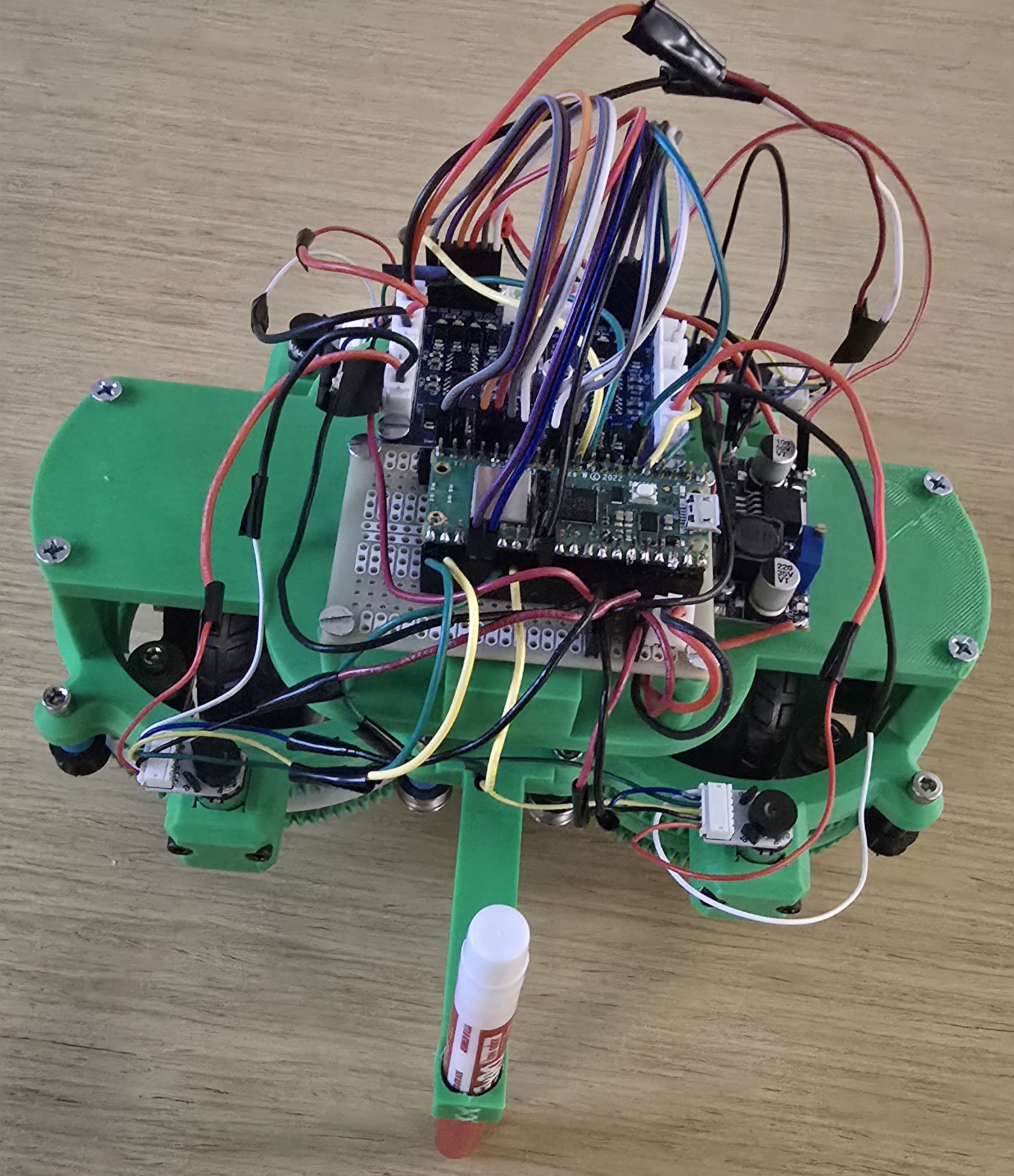
Penny the Plotter is a remotely controlled swerve-drive robot that draws geometric patterns on paper using closed-loop motor control.
Summary
Penny the Plotter is a differential swerve-drive robot designed to draw geometric patterns on a white paper or whiteboard surface. The system combines WiFi communication for remote control with closed-loop PID motor control and quadrature encoders for precise movement. The robot receives drawing commands via UDP from a Python control script running on a laptop, which simultaneously visualizes the path using python turtle graphics.
The motivation for this project was to create a platform that combines multiple engineering disciplines: embedded systems programming, mechanical engineering, and robotics. The swerve-drive mechanism provides omnidirectional movement capabilities, allowing the robot to draw complex paths including curves and sharp turns.
2. High Level Design
Rationale and Sources
The project idea was inspired by HTX studio's whiteboard plotter robot, but adapted to use swerve drive technology and to drive on the floor. Swerve drive systems are commonly used in competitive robotics (FIRST Robotics, VEX) for their omnidirectional capabilities. The differential swerve design allows each wheel module to independently control both translation and rotation, enabling smooth curved movements ideal for drawing.
Background Math
Differential Swerve Kinematics
For a differential swerve module with two motors (m1, m2), the wheel speed and steering angle are calculated as:
wheel_speed = (m1 - m2) / 2
steering_angle = (m1 + m2) / 2
For the entire robot with two modules (A and B), forward/backward translation requires:
Module A: m1 = +speed, m2 = -speed
Module B: m1 = +speed, m2 = -speed
Rotation in place requires:
Module A: m1 = +yaw, m2 = +yaw
Module B: m1 = +yaw, m2 = +yaw
PID Control
The motor control uses proportional (P) control with gain Kp = 0.25:
error = target_speed - actual_speed
duty_change = error × Kp
new_duty = current_duty + duty_change
Logical Structure
The system consists of two main components:
- Robot (Pico W): Runs C code with protothreads for:
- WiFi communication (UDP receive/send)
- Motor control (closed-loop PID)
- Encoder quadrature decoding (ISR-based)
- LED indicator for UDP
- Control Script (Python): High-level path planning:
- Turtle graphics visualization
- UDP command generation
- Timing coordination
Hardware/Software Tradeoffs
| Design Decision | Hardware Cost | Software Cost | Benefit Gained |
|---|---|---|---|
| Added Quadrature Encoders | 4 additional sensors, 8 GPIO pins consumed, more wiring complexity | 4 additional ISR handlers, encoder counting threads, more complex motor control logic | Closed-loop speed control enabling precise motor synchronization |
| Differential Swerve Drive | Motor count of 4, 4 motor driver channels, higher power consumption | Complex differential kinematics implementation, sign convention handling for mirrored modules | Omnidirectional movement without separate steering actuators |
| WiFi/UDP Communication | Required Pico W (vs standard Pico) | Full lwIP stack integration, UDP threading, packet parsing, connection handling | Untethered operation, real-time remote control, and path visualization on laptop |
| Software PID (vs Open-Loop) | None additional | PID calculation thread, tuning parameters | Motor speed matching within ±5%, prevents drifting |
| Protothread Concurrency | None additional | Thread management overhead, state machine design, shared variable synchronization | Simultaneous motor control, UDP communication, and LED status without RTOS complexity |
Patents, Copyrights, and Trademarks
Relevant intellectual property considerations:
- Protothreads: Cornell ECE4760 library - provided for course use.
- UDP Communication: Based on code by Andrew McDonnel - provided for course use.
3. Program/Hardware Design
Program Details
C Code (robot.c)
The main robot firmware runs on the Raspberry Pi Pico W with the key components being:
- Motor Control Thread: 50ms control loop implementing PID for speed regulation. Uses encoder feedback to adjust PWM duty cycles. Handles four cases: stopping, pure translation, pure rotation, and mixed arc motion.
- UDP Receive Thread: Parses incoming commands in format "<linear> <angular>" and updates motor setpoints. Includes error handling for malformed packets.
- UDP Send Thread: Sends debug information back to computer including motor duties, encoder counts, and packet statistics.
- Encoder ISR: Quadrature decoding in interrupt service routine. Updates global encoder counts for all four motors.
Tricky Parts:
- Differential Swerve Math: Getting the sign conventions correct for left vs right modules required testing. Module B needed opposite wheel command signs due to physical mirroring.
- PID Tuning: Initial implementation caused motors to overshoot. Added rate limiting (max 50 units per loop) to prevent rapid duty changes.
- Open-Loop Startup: Motors initially waited for encoder feedback, causing lag. Fixed by initializing duties to setpoint values on command start.
- PWM Slice Conflicts: Had to ensure all four enable pins use different PWM slices to avoid conflicts.
Python Control Scripts
datasender.py: Handles UDP socket communication with the Pico W. Creates a UDP socket
connection to the robot's IP address and port, provides a forward() method to send string
commands, and exposes a robot attribute for high-level control. Includes IP/port validation
via InvalidAddressError.
robot_instr.py: Provides a high-level API for robot motion commands. Wraps the datasender
to offer intuitive methods like move_forward(), move_backward(),
rotate_ccw(), rotate_cw(), and stop(). Also supports arc motions
via arc_forward_left() and similar methods. All speeds are clamped to 300 (MAX_SPEED) and
commands are formatted as "linear angular" strings for UDP transmission.
draw_L.py: Generates L-shaped drawing pattern with curved rotations.
draw_square.py: Generates square drawing pattern with curved rotations.
All commands sent over UDP are sent continuously (every 50ms) to prevent packet loss. We use Python turtle package for visualization with curved arc animations matching swerve drive behavior.
Hardware Details
CAD Files
Our CAD files for the differential swerve drive mechanism are available for download. The complete CAD model files contain the 3D models and design specifications for the swerve drive modules and our chassis that was used in this project.
| File Name | Download |
|---|---|
| Chassis.step | Download |
| Roller_0_3_mm.step | Download |
| swerve - base.stl | Download |
| swerve - bracket.stl | Download |
| swerve - frame.stl | Download |
| swerve - large gear.stl | Download |
| swerve - long motor gear.stl | Download |
| swerve - middle gear.stl | Download |
| swerve - motor lid.stl | Download |
| swerve - short motor gear.stl | Download |
| swerve - spacer.stl | Download |
| swerve - wheel hex.stl | Download |
| swerve - wheel spacer.stl | Download |
| swerve.step | Download |
Motor Control
| Component | Part | Specifications |
|---|---|---|
| Microcontroller | Raspberry Pi Pico W | RP2040, 133MHz, WiFi (CYW43) |
| Motor Drivers | OSOYOO Model Y 4-Channel H-Bridge | PT5126 chips, 4 independent channels, 2.8A max per channel, 2.0-24V motor supply, 2.7-5.5V logic |
| Motors | N20 DC Motor with Magnetic Encoder (Adafruit #4638) | 4x motors, 6V nominal, 1:50 gear ratio, built-in magnetic encoder with hall effect sensors, 14 counts/revolution, ~100mA current draw |
Pin Mapping
| Function | GPIO Pins |
|---|---|
| Module A1 (Left) | EN: GP10, IN1: GP11, IN2: GP12 |
| Module A2 (Left) | EN: GP13, IN1: GP14, IN2: GP15 |
| Module B1 (Right) | EN: GP4, IN1: GP19, IN2: GP18 |
| Module B2 (Right) | EN: GP22, IN1: GP8, IN2: GP9 |
| Encoders | A1: GP6/7, A2: GP16/17, B1: GP2/3, B2: GP20/21 |
Power System
The system uses a single 6V 900mA battery pack as the primary power source. The battery directly powers the motors and the OSOYOO Model Y motor driver's VM (motor supply) input. A buck converter (logic converter) steps down the 6V battery voltage to 3.3V to power the Raspberry Pi Pico W, eliminating the need for a separate USB power connection. The motor driver's VCC (logic supply) receives 5V, which can be provided by the battery through a voltage regulator or a separate 5V supply if needed.
Build Instructions
To build this project:
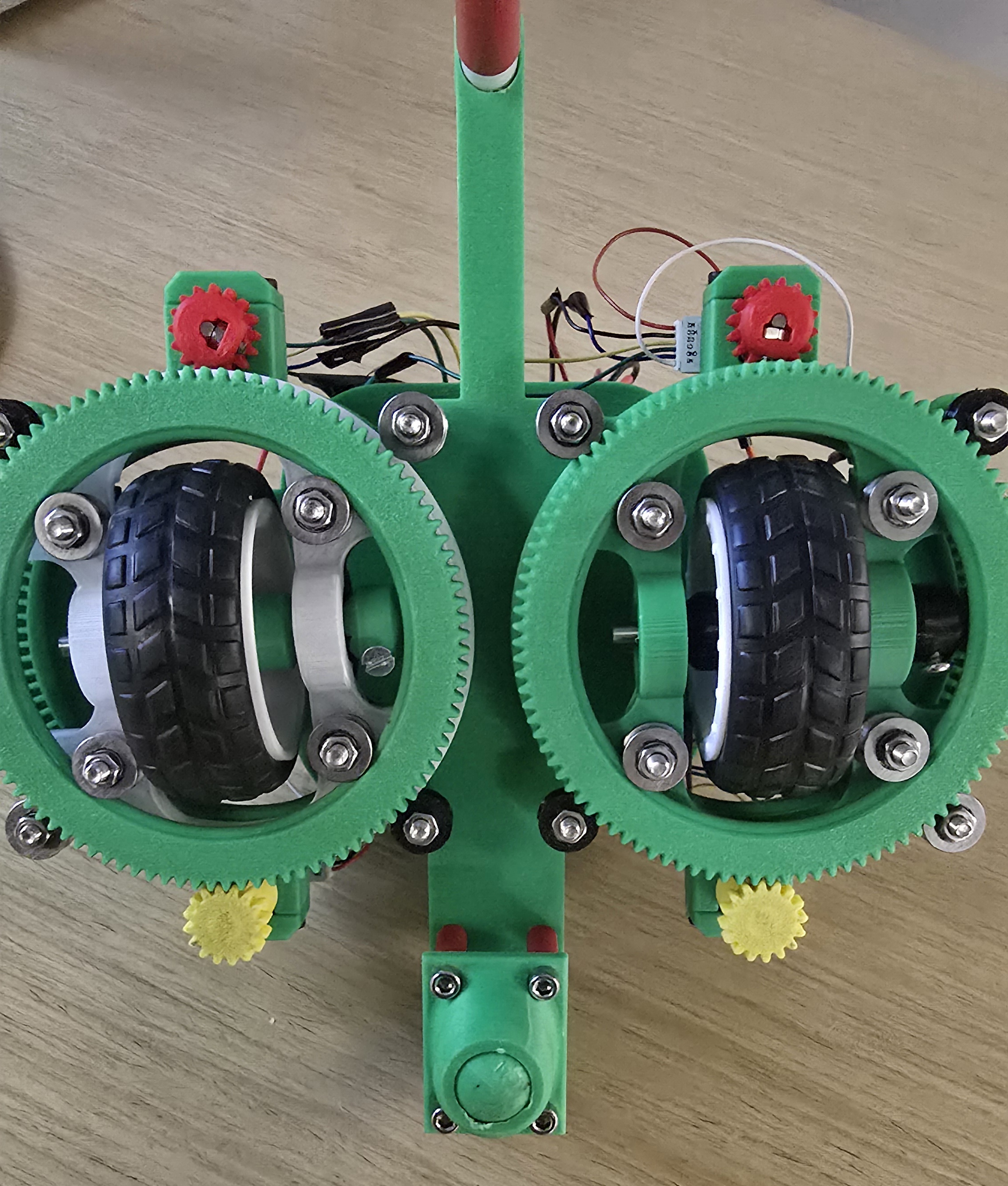
- Print and assemble two swerve drive modules with two motors each using the CAD files provided, bearings, bolts, nuts, axles, and wheels.
- Connect the swerve drive modules to the 3d-printed chassis using bolts and nuts.
- Mount OSOYOO Model Y 4-channel motor driver and RP2040 Pico W onto the chassis using screws on the standoffs. Note that the Pico W is mounted on a protoboard to allow for easy connection to the chassis.
- Connect motors to the driver sockets of the motor controller: AK1/AK2, AK3/AK4, BK1/BK2, BK3/BK4
- Connect PWM pins (ENA/ENB for each channel) and direction pins (IN1-IN4 for each channel) to Pico GPIO
- Wire encoders: A/B channels to GPIO pins with pull-up resistors
- Connect Pico W GPIO pins as specified in pin mapping table
- Use the Vout channel to connect the motor controller to a buck converter to power the Pico W
- Connect the 6V 900mA battery to the Vin channel of the motor controller
- Flash robot.c to Pico W
- Configure WiFi credentials in robot.c
- Run Python scripts on host computer
Code/Designs Borrowed from Others
The following code and libraries were borrowed from the ECE 4760 course materials and other sources:
- pt_cornell_rp2040_v1_4.h: Protothreads library for cooperative multitasking on the RP2040.
Provides lightweight threading primitives (
PT_BEGIN,PT_END,PT_YIELD,PT_SEM_WAIT,PT_SEM_SIGNAL) that enable concurrent execution without a full RTOS. Source: Cornell ECE 4760 course library by V. Hunter Adams. - lwipopts.h / lwipopts_examples_common.h: Configuration headers for the lwIP (Lightweight IP) TCP/IP stack. These define memory allocation, protocol options, and network buffer settings optimized for embedded systems. Source: Raspberry Pi Pico SDK examples.
- UDP Communication Code: The UDP send/receive structure in
robot.cis based on the lwIP raw API examples. Key functions includeudp_new(),udp_bind(),udp_recv(), andudp_sendto()for connectionless network communication. The callback-based receive pattern (udpecho_raw_recv) follows the lwIP documentation examples. - connect.h: WiFi connection helper code adapted from ECE 4760 course examples, providing a simple interface for connecting the Pico W to a WiFi access point using the CYW43 driver.
Things That Did Not Work
- Initial Backward Movement: Module B needed opposite sign convention due to physical mirroring. Fixed by negating wheel component for Module B.
- PID Overshoot: Motors would jump to max duty immediately. Added rate limiting to cap duty changes at 50 units per control loop.
- Encoder Lag: Motors waited for encoder feedback before starting. Fixed with open-loop initialization to setpoint values.
- PWM Slice Conflicts: GP10 and GP26 shared same slice/channel. Changed EN_B1 to GP4 to use different slice.
- CMake Build Loop: Build directory corruption caused infinite reconfiguration. Fixed by cleaning build directory.
AI Use Discussion
ChatGPT was used for:
- Code debugging and error diagnosis for the quadrature encoders. Specificaly, we used ChatGPT to help us with our equalization logic for the motors. Note that AI was not used to code, but rather as a reference.
- Creating HTML documentation structure
All code was reviewed, tested, and modified based on actual hardware behavior. The AI served as a assistant with design decisions and debugging, but all hardware and software integration was done by the team.
4. Results of the Design
Test Data
Motor Control Performance:
- Control loop frequency: 20 Hz (50ms period)
- PWM frequency: ~1 kHz (100.0 clock divider)
- Encoder update rate: Event-driven (ISR on edge transitions)
- UDP command rate: 20 Hz (50ms interval)
Movement Timing (calibrated):
- Forward 1 unit: 1.3 seconds
- Rotate 90°: 0.5 seconds
- Command interval: 50ms (20 commands/second)
Debug Output Example:
Motor duties: A1=300 A2=-300 B1=300 B2=-300 | Setpoints: A1=300 A2=-300 B1=300 B2=-300
Encoder deltas: A1=45 A2=-42 B1=43 B2=-44
[RX] lin=300 ang=0
Speed of Execution
- No hesitation: While our open-loop startup ensures immediate motor response, physical constraints such as friction and slipping causes our robot to hesitate/lag.
- No flicker: Continuous UDP commands (50ms interval) prevent command drops
- Concurrency: Protothreads allow motor control, UDP, and LED to run simultaneously
Accuracy
- Motor Speed: PID control maintains ~ ±8% speed matching between motors
- Rotation: 90° rotations accurate to ~ ±13° after calibration
- Straight Lines: Encoder feedback keeps robot moving straight most of the time
Safety
- Duty Cycle Limits: All motor commands clamped to ±300 (MAX_DUTY)
- Rate Limiting: Maximum duty change of 50 units per control loop prevents sudden jumps
- Emergency Stop: Robot responds to stop command (0,0) within 50ms
- Encoder Bounds Checking: Encoder deltas checked for reasonable values
- Power Protection: Motor drivers include overcurrent protection
- Software Watchdog: Protothread scheduling prevents infinite loops
Usability
For Developers:
- Clear code structure with comments
- Debug output shows motor states and encoder counts
- Python scripts are easy to modify for different patterns
- WiFi configuration straightforward (change SSID/password)
- Simple Python script execution:
python draw_square.py - Visual feedback via turtle graphics
- Automatic WiFi connection with retry logic
For End Users:
5. Conclusions
Design Analysis
The project did not meet its primary goals: creating a mobile drawing robot with precise motor control on a whiteboard (only able to get it to draw on the floor).
What Worked Well:
- Swerve module design was successful in providing omnidirectional movement
- UDP communication is reliable with continuous sending
What Could Be Improved:
- Add pen up/down mechanism for actual drawing
- Changing the motors to a lower gear ratio or higher power
- Switching to absolute encoders instead of quadrature encoders
- Implement computer vision for more precise movement
- Caster wheel was 3D printed rather than purchased, so it is not as smooth as it could be
- IEEE 802.11 (WiFi): Pico W uses standard WiFi protocols for communication
- UDP/IP: Standard UDP protocol for network communication
- PWM Standards: 1kHz PWM frequency is standard for motor control
- Safety: Motor duty limits and rate limiting follow embedded systems practices
Standards Conformance
6. Intellectual Property Considerations
Code Reuse
- Protothreads: Cornell ECE4760 course library - provided for educational use
- lwIP: Lightweight IP stack - open source (BSD license)
- Python Standard Library: socket, time, turtle - standard library, no restrictions
- FIRST Robotics: We took inspiration from FIRST Robotics code for differential swerve drive and quadrature encoders
Design Reuse
- Differential Swerve Kinematics: Based on FIRST Robotics designs. General concepts are in public domain.
- PID Control: Standard control theory, widely published and in public domain.
Public Domain Code
All libraries used are open source with permissive licenses (BSD, MIT). No proprietary code was used. All project-specific code was written by the team.
Reverse Engineering
No reverse engineering was performed. Motor drivers (L298N) are standard components with publicly available datasheets. Swerve drive mechanisms are well-documented in robotics literature.
Non-Disclosure Agreements
No NDAs were signed. All components used are commercially available with public documentation.
Patent Opportunities
While the project demonstrates integration of existing technologies, no novel patentable inventions were created. The value is in the system integration and application rather than fundamental innovation. Potential improvements (path following algorithms, calibration routines) could be developed further but would require more extensive research.
Appendix A: Permissions
Project on the Course Page
"The group approves this report for inclusion on the course website."
Project on the Course YouTube Channel
"The group approves the video for inclusion on the course youtube channel."
Appendix B: Code Listings
robot/robot.c
Click to expand/collapse code
/**
 * Copyright (c) 2022 Andrew McDonnell
 *
 * SPDX-License-Identifier: BSD-3-Clause
 */

// Standard libraries
#include <string.h>
#include <stdlib.h>
#include <stdbool.h>
#include <pico/multicore.h>
#include "hardware/sync.h"
#include "hardware/gpio.h"
#include "hardware/timer.h"
#include "hardware/uart.h"
#include "hardware/pwm.h"
#include "stdio.h"

#include "pico/stdlib.h"
#include "pico/cyw43_arch.h"

#include "lwip/pbuf.h"
#include "lwip/udp.h"
#include "lwip/opt.h"
#include "lwip/debug.h"
#include "lwip/stats.h"
#include "lwip/dns.h"
#include "lwip/netif.h"
#include "pt_cornell_rp2040_v1_4.h"

// udp constants
#define UDP_PORT 5555
#define UDP_MSG_LEN_MAX 64
#define UDP_TARGET "-----" // laptop address
#define UDP_INTERVAL_MS 10

// Module A
#define EN_A1   10
#define IN1_A1  11
#define IN2_A1  12

#define EN_A2   13
#define IN1_A2  14
#define IN2_A2  15

// Module B
#define EN_B1   4
#define IN1_B1  19
#define IN2_B1  18

#define EN_B2   22
#define IN1_B2  8
#define IN2_B2  9

// PWM duty cycle max
#define MAX_DUTY 500

// ENCODER DEFINES
#define ENC_A1_A    6
#define ENC_A1_B    7

#define ENC_A2_A    16
#define ENC_A2_B    17

#define ENC_B1_A    2
#define ENC_B1_B    3

#define ENC_B2_A    20
#define ENC_B2_B    21

// Encoder global state
volatile int32_t enc_count_a1 = 0;
volatile int32_t enc_count_a2 = 0;
volatile int32_t enc_count_b1 = 0;
volatile int32_t enc_count_b2 = 0;

// Motor speed setpoints
volatile int mA1_sp = 0;
volatile int mA2_sp = 0;
volatile int mB1_sp = 0;
volatile int mB2_sp = 0;

// PWM duties applied to motors
static int duty_A1 = 0;
static int duty_A2 = 0;
static int duty_B1 = 0;
static int duty_B2 = 0;

// Simple proportional gains
#define MOTOR_KP_NUM 1
#define MOTOR_KP_DEN 4   // Kp = 0.25

// Motor Control Helper Functions
void pwm_setup(uint pin) {
    gpio_set_function(pin, GPIO_FUNC_PWM);
    uint slice = pwm_gpio_to_slice_num(pin);
    pwm_set_wrap(slice, MAX_DUTY);
    pwm_set_clkdiv(slice, 100.0f);   // ~1 kHz PWM
    pwm_set_enabled(slice, true);
}

void motor_set(int in1, int in2, int en, int duty) {
    gpio_put(in1, duty > 0);
    gpio_put(in2, duty < 0);
    uint slice = pwm_gpio_to_slice_num(en);
    uint level = abs(duty);
    if (level > MAX_DUTY) level = MAX_DUTY;
    pwm_set_chan_level(slice, pwm_gpio_to_channel(en), level);
}

void stop_motor(int in1, int in2, int en) {
    gpio_put(in1, 0);
    gpio_put(in2, 0);
    uint slice = pwm_gpio_to_slice_num(en);
    pwm_set_chan_level(slice, pwm_gpio_to_channel(en), 0);
}


// Encoder Quadrature Decoding (ISR)
void encoder_isr(uint gpio, uint32_t events) {
    bool a_state, b_state;

    if (gpio == ENC_A1_A) {
        a_state = gpio_get(ENC_A1_A);
        b_state = gpio_get(ENC_A1_B);
        if (a_state == b_state) enc_count_a1++;
        else                    enc_count_a1--;
    }
    else if (gpio == ENC_A2_A) {
        a_state = gpio_get(ENC_A2_A);
        b_state = gpio_get(ENC_A2_B);
        if (a_state == b_state) enc_count_a2++;
        else                    enc_count_a2--;
    }
    else if (gpio == ENC_B1_A) {
        a_state = gpio_get(ENC_B1_A);
        b_state = gpio_get(ENC_B1_B);
        if (a_state == b_state) enc_count_b1++;
        else                    enc_count_b1--;
    }
    else if (gpio == ENC_B2_A) {
        a_state = gpio_get(ENC_B2_A);
        b_state = gpio_get(ENC_B2_B);
        if (a_state == b_state) enc_count_b2++;
        else                    enc_count_b2--;
    }
}


// Encoder Initialization
void encoder_init() {
    int enc_a_pins[] = {ENC_A1_A, ENC_A2_A, ENC_B1_A, ENC_B2_A};
    int enc_b_pins[] = {ENC_A1_B, ENC_A2_B, ENC_B1_B, ENC_B2_B};

    for (int i = 0; i < 4; i++) {
        // Channel A - triggers interrupt
        gpio_init(enc_a_pins[i]);
        gpio_set_dir(enc_a_pins[i], GPIO_IN);
        gpio_pull_up(enc_a_pins[i]);

        // Channel B - read for direction
        gpio_init(enc_b_pins[i]);
        gpio_set_dir(enc_b_pins[i], GPIO_IN);
        gpio_pull_up(enc_b_pins[i]);
    }

    // Shared callback for all A channels
    gpio_set_irq_enabled_with_callback(
        ENC_A1_A,
        GPIO_IRQ_EDGE_RISE | GPIO_IRQ_EDGE_FALL,
        true,
        &encoder_isr
    );

    gpio_set_irq_enabled(ENC_A2_A, GPIO_IRQ_EDGE_RISE | GPIO_IRQ_EDGE_FALL, true);
    gpio_set_irq_enabled(ENC_B1_A, GPIO_IRQ_EDGE_RISE | GPIO_IRQ_EDGE_FALL, true);
    gpio_set_irq_enabled(ENC_B2_A, GPIO_IRQ_EDGE_RISE | GPIO_IRQ_EDGE_FALL, true);
}

// MODULE A (Left)
void moduleA_motor1(int duty) { motor_set(IN1_A1, IN2_A1, EN_A1, duty); }
void moduleA_motor2(int duty) { motor_set(IN1_A2, IN2_A2, EN_A2, duty); }

void moduleA_stop() {
    stop_motor(IN1_A1, IN2_A1, EN_A1);
    stop_motor(IN1_A2, IN2_A2, EN_A2);
}

// MODULE B (Right)
void moduleB_motor1(int duty) { motor_set(IN1_B1, IN2_B1, EN_B1, duty); }
void moduleB_motor2(int duty) { motor_set(IN1_B2, IN2_B2, EN_B2, duty); }

void moduleB_stop() {
    stop_motor(IN1_B1, IN2_B1, EN_B1);
    stop_motor(IN1_B2, IN2_B2, EN_B2);
}


volatile int linear_cmd  = 0;
volatile int angular_cmd = 0;

void update_motor_setpoints_from_cmd(void) {
    int wheel = linear_cmd;
    int yaw   = angular_cmd;
    mA1_sp = yaw + wheel;
    mA2_sp = yaw - wheel;
    mB1_sp = yaw + wheel;
    mB2_sp = yaw - wheel;
}

// Drive Helper
void robot_drive(int linear, int angular) {
    if (linear >  MAX_DUTY) linear =  MAX_DUTY;
    if (linear < -MAX_DUTY) linear = -MAX_DUTY;
    if (angular >  MAX_DUTY) angular =  MAX_DUTY;
    if (angular < -MAX_DUTY) angular = -MAX_DUTY;

    linear_cmd  = linear;
    angular_cmd = angular;
    update_motor_setpoints_from_cmd();
}

void robot_forward(int speed)  { robot_drive(+speed, 0); }
void robot_backward(int speed) { robot_drive(-speed, 0); }
void robot_rotate_left(int yaw){ robot_drive(0, +yaw); }
void robot_rotate_right(int yaw){ robot_drive(0, -yaw); }

void robot_stop() {
    robot_drive(0, 0);
    duty_A1 = duty_A2 = duty_B1 = duty_B2 = 0;
    moduleA_stop();
    moduleB_stop();
}

// WIFI
#define WIFI_SSID "---"
#define WIFI_PASSWORD "---"

char recv_data[UDP_MSG_LEN_MAX];

volatile uint32_t packets_received = 0;
volatile uint32_t packets_sent = 0;
volatile uint32_t parse_errors = 0;
volatile uint32_t last_recv_time_ms = 0;

struct pt_sem new_udp_recv_s, new_udp_send_s ;

#if LWIP_UDP

static struct udp_pcb *udpecho_raw_pcb;
struct pbuf *p ;

static void
udpecho_raw_recv(void *arg, struct udp_pcb *upcb, struct pbuf *p,
                 const ip_addr_t *addr, u16_t port)
{
  LWIP_UNUSED_ARG(arg);

  if (p != NULL) {
    memcpy(recv_data, p->payload, UDP_MSG_LEN_MAX);
    PT_SEM_SIGNAL(pt, &new_udp_recv_s) ;
    pbuf_free(p);
  }
  else printf("NULL pt in callback");
}

void udpecho_raw_init(void)
{
  udpecho_raw_pcb = udp_new_ip_type(IPADDR_TYPE_ANY);
  p = pbuf_alloc(PBUF_TRANSPORT, UDP_MSG_LEN_MAX+1, PBUF_RAM);

  if (udpecho_raw_pcb != NULL) {
    err_t err;
    err = udp_bind(udpecho_raw_pcb, netif_ip4_addr(netif_list), UDP_PORT); //DHCP addr

    if (err == ERR_OK) {
      udp_recv(udpecho_raw_pcb, udpecho_raw_recv, NULL);
    } else {
      printf("bind error");
    }
  } else {
    printf("udpecho_raw_pcb error");
  }
}

#endif /* LWIP_UDP */

// UDP Send Thread
static PT_THREAD (protothread_udp_send(struct pt *pt))
{
    PT_BEGIN(pt);
    static struct udp_pcb* pcb;
    pcb = udp_new();
    pcb->remote_port = UDP_PORT ;
    pcb->local_port = UDP_PORT ;

    static ip_addr_t addr;
    ipaddr_aton(UDP_TARGET, &addr);

    while (true) {
        PT_SEM_WAIT(pt, &new_udp_send_s) ;

        struct pbuf *p = pbuf_alloc(PBUF_TRANSPORT, UDP_MSG_LEN_MAX+1, PBUF_RAM);
        char *req = (char *)p->payload;
        memset(req, 0, UDP_MSG_LEN_MAX+1);

        uint32_t uptime_ms = to_ms_since_boot(get_absolute_time());
        sprintf(req, "%lu|%d,%d|rx:%lu,err:%lu",
                packets_sent,
                linear_cmd, angular_cmd,
                packets_received,
                parse_errors);

        err_t er = udp_sendto(pcb, p, &addr, UDP_PORT);
        pbuf_free(p);
        if (er != ERR_OK) {
            printf("UDP send error=%d\n", er);
        } else {
            packets_sent++;
        }

#if PICO_CYW43_ARCH_POLL
        cyw43_arch_poll();
        sleep_ms(BEACON_INTERVAL_MS);
#else
        PT_YIELD_usec(UDP_INTERVAL_MS * 1000);
#endif
    }

    PT_END(pt);
}


// Thread for UDP to parse motor commands
static PT_THREAD (protothread_udp_recv(struct pt *pt))
{
    PT_BEGIN(pt);
    PT_INTERVAL_INIT();

    while(1) {
        PT_SEM_WAIT(pt, &new_udp_recv_s) ;

        packets_received++;
        last_recv_time_ms = to_ms_since_boot(get_absolute_time());

        int new_linear = 0, new_angular = 0;
        int parsed = sscanf(recv_data, "%d %d", &new_linear, &new_angular);

        if (parsed == 2) {
            robot_drive(new_linear, new_angular);
            printf("[RX] lin=%d ang=%d\n", linear_cmd, angular_cmd);
        } else {
            parse_errors++;
            printf("[ERR] Bad packet: '%s' (parsed %d)\n", recv_data, parsed);
        }

        PT_SEM_SIGNAL(pt, &new_udp_send_s) ;
        PT_YIELD_INTERVAL(10);
    }
    PT_END(pt);
}

// Toggle LED for UDP
static PT_THREAD (protothread_toggle_cyw43(struct pt *pt))
{
    PT_BEGIN(pt);
    static bool LED_state = false ;
    PT_INTERVAL_INIT();

    while(1) {
        LED_state = !LED_state ;
        cyw43_arch_gpio_put(CYW43_WL_GPIO_LED_PIN, LED_state);
        PT_YIELD_INTERVAL(500000); // 500 ms
    }

    PT_END(pt);
}

// helper to get sign
static inline int sgn(int x) {
    if (x > 0) return 1;
    if (x < 0) return -1;
    return 0;
}

// Proportional control relative to a target magnitude
static void equalize_to_ref(
    int *duty, int ref_mag, int actual_delta, int desired_sign)
{
    if (desired_sign == 0) {
        *duty = 0;
        return;
    }

    // initialize to a minimum value
    if (*duty == 0 && ref_mag > 0) {
        *duty = desired_sign * (ref_mag / 2);  // Start at half the reference
        return;
    }

    int actual_mag = abs(actual_delta);
    int error      = ref_mag - actual_mag;
    int delta      = (error * MOTOR_KP_NUM) / MOTOR_KP_DEN;

    int new_mag = abs(*duty) + delta;

    // Rate limiting
    int max_change = 50;
    int current_mag = abs(*duty);
    if (new_mag > current_mag + max_change) {
        new_mag = current_mag + max_change;
    } else if (new_mag < current_mag - max_change) {
        new_mag = current_mag - max_change;
    }

    if (new_mag < 0)          new_mag = 0;
    if (new_mag > MAX_DUTY)   new_mag = MAX_DUTY;

    *duty = desired_sign * new_mag;
}

// per-motor control to track its own setpoint magnitude
static void track_own_setpoint(
    int *duty, int setpoint, int actual_delta)
{
    int sig = sgn(setpoint);
    if (sig == 0) {
        *duty = 0;
        return;
    }

    int target_mag = abs(setpoint);
    int actual_mag = abs(actual_delta);
    int error      = target_mag - actual_mag;
    int delta      = (error * MOTOR_KP_NUM) / MOTOR_KP_DEN;

    int new_mag = abs(*duty) + delta;

    // Rate limiting
    int max_change = 50;
    int current_mag = abs(*duty);
    if (new_mag > current_mag + max_change) {
        new_mag = current_mag + max_change;
    } else if (new_mag < current_mag - max_change) {
        new_mag = current_mag - max_change;
    }

    if (new_mag < 0)        new_mag = 0;
    if (new_mag > MAX_DUTY) new_mag = MAX_DUTY;

    *duty = sig * new_mag;
}

static PT_THREAD (protothread_motor_control(struct pt *pt))
{
    PT_BEGIN(pt);
    PT_INTERVAL_INIT();

    static int32_t last_a1 = 0;
    static int32_t last_a2 = 0;
    static int32_t last_b1 = 0;
    static int32_t last_b2 = 0;
    static bool initialized = false;

    while (1) {
        // Encoder counts and compute deltas
        int32_t cA1 = enc_count_a1;
        int32_t cA2 = enc_count_a2;
        int32_t cB1 = enc_count_b1;
        int32_t cB2 = enc_count_b2;

        int32_t dA1 = cA1 - last_a1;
        int32_t dA2 = cA2 - last_a2;
        int32_t dB1 = cB1 - last_b1;
        int32_t dB2 = cB2 - last_b2;

        last_a1 = cA1;
        last_a2 = cA2;
        last_b1 = cB1;
        last_b2 = cB2;

        int sigA1 = sgn(mA1_sp);
        int sigA2 = sgn(mA2_sp);
        int sigB1 = sgn(mB1_sp);
        int sigB2 = sgn(mB2_sp);

        // Case 1: robot stopped
        if (linear_cmd == 0 && angular_cmd == 0) {
            duty_A1 = duty_A2 = duty_B1 = duty_B2 = 0;
            initialized = false;
        }
        // Case 2: pure forward/backward -> equalize all motors to one reference
        else if (angular_cmd == 0 && linear_cmd != 0) {
            // Initialize duties to setpoint values
            if (!initialized) {
                duty_A1 = mA1_sp;
                duty_A2 = mA2_sp;
                duty_B1 = mB1_sp;
                duty_B2 = mB2_sp;
                initialized = true;
                printf("[CTRL] Open-loop startup: A1=%d A2=%d B1=%d B2=%d\n",
                       duty_A1, duty_A2, duty_B1, duty_B2);
            }

            // Use A2 or B1 as reference
            int a2_encoder = (dA2 != 0) ? dA2 : dB2;
            int ref_mag = abs(a2_encoder);
            if (ref_mag < 1) {
                ref_mag = abs(dB1);
                if (ref_mag < 1) {
                    ref_mag = abs(mA1_sp);
                }
            }

            // All motors equalize to the same reference magnitude
            equalize_to_ref(&duty_A1, ref_mag, dA1, sigA1);
            equalize_to_ref(&duty_A2, ref_mag, a2_encoder, sigA2);
            duty_B2 = duty_A2;
            equalize_to_ref(&duty_B1, ref_mag, dB1, sigB1);
        }
        // Case 3: pure rotation
        else if (linear_cmd == 0 && angular_cmd != 0) {
            if (!initialized) {
                duty_A1 = mA1_sp;
                duty_A2 = mA2_sp;
                duty_B1 = mB1_sp;
                duty_B2 = mB2_sp;
                initialized = true;
                printf("[CTRL] Open-loop startup (rotation): A1=%d A2=%d B1=%d B2=%d\n",
                       duty_A1, duty_A2, duty_B1, duty_B2);
            }

            int ref_mag = abs(dA1);
            if (ref_mag < 1) ref_mag = abs(mA1_sp);

            track_own_setpoint(&duty_A1, mA1_sp, dA1);
            int a2_encoder = (dA2 != 0) ? dA2 : dB2;
            equalize_to_ref(&duty_A2, ref_mag, a2_encoder, sigA2);
            duty_B2 = duty_A2;

            equalize_to_ref(&duty_B1, ref_mag, dB1, sigB1);
        }
        // Case 4: mixed arc motion
        else {

            if (!initialized) {
                duty_A1 = mA1_sp;
                duty_A2 = mA2_sp;
                duty_B1 = mB1_sp;
                duty_B2 = mB2_sp;
                initialized = true;
                printf("[CTRL] Open-loop startup (arc): A1=%d A2=%d B1=%d B2=%d\n",
                       duty_A1, duty_A2, duty_B1, duty_B2);
            }

            track_own_setpoint(&duty_A1, mA1_sp, dA1);
            int a2_encoder = (dA2 != 0) ? dA2 : dB2;
            track_own_setpoint(&duty_A2, mA2_sp, a2_encoder);
            duty_B2 = duty_A2;

            track_own_setpoint(&duty_B1, mB1_sp, dB1);
        }

        // Apply updated duties
        moduleA_motor1(duty_A1);
        moduleA_motor2(duty_A2);
        moduleB_motor1(duty_B1);
        moduleB_motor2(duty_B2);

        PT_YIELD_INTERVAL(50000); // 50 ms control loop
    }

    PT_END(pt);
}

// ====================================================
// Motor GPIO/PWM initialization
// ====================================================
void motor_init() {
    int standard_pins[] = {
        EN_A1, IN1_A1, IN2_A1,
        EN_A2, IN1_A2, IN2_A2,
        EN_B1, IN1_B1, IN2_B1,
        EN_B2, IN1_B2, IN2_B2
    };

    for (int i = 0; i < 12; i++) {
        gpio_init(standard_pins[i]);
        gpio_set_dir(standard_pins[i], GPIO_OUT);
    }

    pwm_setup(EN_A1);
    pwm_setup(EN_A2);
    pwm_setup(EN_B1);
    pwm_setup(EN_B2);

    // Print PWM slice info for debugging
    printf("PWM Slice Assignments:\n");
    printf("  EN_A1 (GP%d): Slice %d, Channel %c\n", EN_A1, pwm_gpio_to_slice_num(EN_A1), pwm_gpio_to_channel(EN_A1) ? 'B' : 'A');
    printf("  EN_A2 (GP%d): Slice %d, Channel %c\n", EN_A2, pwm_gpio_to_slice_num(EN_A2), pwm_gpio_to_channel(EN_A2) ? 'B' : 'A');
    printf("  EN_B1 (GP%d): Slice %d, Channel %c\n", EN_B1, pwm_gpio_to_slice_num(EN_B1), pwm_gpio_to_channel(EN_B1) ? 'B' : 'A');
    printf("  EN_B2 (GP%d): Slice %d, Channel %c\n", EN_B2, pwm_gpio_to_slice_num(EN_B2), pwm_gpio_to_channel(EN_B2) ? 'B' : 'A');

    robot_stop();
}

// ====================================================
int main() {
    stdio_init_all();

    motor_init();
    printf("Motors initialized\n");

    encoder_init();
    printf("Encoders initialized\n");

    printf("Waiting for power to stabilize...\n");
    sleep_ms(1000);

    if (cyw43_arch_init()) {
        printf("failed to initialise cyw43\n");
        return 1;
    }

    cyw43_arch_enable_sta_mode();

    int max_retries = 5;
    int retry_count = 0;
    bool connected = false;

    while (!connected && retry_count < max_retries) {
        printf("WiFi connection attempt %d/%d...\n", retry_count + 1, max_retries);

        if (cyw43_arch_wifi_connect_timeout_ms(
                WIFI_SSID, WIFI_PASSWORD,
                CYW43_AUTH_WPA2_AES_PSK, 30000) == 0) {
            connected = true;
            printf("Connected: picoW IP addr: %s\n",
                   ip4addr_ntoa(netif_ip4_addr(netif_list)));
        } else {
            printf("Connection attempt %d failed, retrying...\n",
                   retry_count + 1);
            retry_count++;
            sleep_ms(2000);
        }
    }

    if (!connected) {
        printf("Failed to connect to WiFi after %d attempts\n", max_retries);
        return 1;
    }

    udpecho_raw_init();

    PT_SEM_INIT(&new_udp_send_s, 0);
    PT_SEM_INIT(&new_udp_recv_s, 0);

    pt_add_thread(protothread_udp_send);
    pt_add_thread(protothread_udp_recv);
    pt_add_thread(protothread_toggle_cyw43);
    pt_add_thread(protothread_motor_control);

    pt_schedule_start;

    cyw43_arch_deinit();
    return 0;
}
local_host/robot_instr.py
Click to expand/collapse code
MAX_SPEED = 500


class robot_instr:

    def __init__(self, sender):
        self._sender = sender

    def _clamp(self, value, min_val=-MAX_SPEED, max_val=MAX_SPEED):
        """Clamp a value to the valid speed range."""
        return max(min_val, min(max_val, value))

    def _send(self, linear, angular):
        """Send a motor command."""
        linear = self._clamp(linear)
        angular = self._clamp(angular)
        self._sender.forward(f"{linear} {angular}")

    def move_forward(self, speed=400):
        self._send(abs(speed), 0)

    def move_backward(self, speed=400):
        self._send(-abs(speed), 0)

    def rotate_ccw(self, speed=400):
        self._send(0, abs(speed))

    def rotate_cw(self, speed=400):
        self._send(0, -abs(speed))

    def stop(self):
        """Stop all motors."""
        self._send(0, 0)

    def drive(self, linear, angular):
        """
        Combined linear and angular movement

        Args:
            linear: Linear speed (-500 to 500, positive=forward)
            angular: Angular speed (-500 to 500, positive=left)
        """
        self._send(linear, angular)

    def arc_forward_left(self, linear, angular):
        self._send(abs(linear), abs(angular))

    def arc_forward_right(self, linear, angular):
        self._send(abs(linear), -abs(angular))

    def arc_backward_left(self, linear, angular):
        self._send(-abs(linear), abs(angular))

    def arc_backward_right(self, linear, angular):
        self._send(-abs(linear), -abs(angular))
local_host/datasender.py
Click to expand/collapse code
import socket
import time
from InvalidAddressError import *
from robot_instr import robot_instr


class datasender():
    def __init__(self, ip, port):
        InvalidAddressError.validate_ip(ip)
        InvalidAddressError.validate_port(port)

        # Define the IP address and port of the Pico W
        self._pico_ip = ip
        self._pico_port = port

        # Create a UDP socket
        self._sock = socket.socket(socket.AF_INET, socket.SOCK_DGRAM)

        # Robot instruction interface
        self.robot = robot_instr(self)

    def forward(self, information):
        # Convert the data to bytes
        data_to_send = f"{information}".encode('utf-8')

        # Send the data to the Pico W
        self._sock.sendto(data_to_send, (self._pico_ip, self._pico_port))

        print(f"Sent: {data_to_send}")

    def close(self):
        self._sock.close()


if __name__ == "__main__":
    # Example usage with robot instructions
    sender = datasender("10.59.35.74", 5555)

    print("Testing robot commands...")

    move_time = time.time()
    curr_time = time.time()

    # 2 sec was a 180 degree turn
    # Test forward
    while (curr_time - move_time < 2.5):
        print("Forward...")
        sender.robot.move_forward()
        curr_time = time.time()
        time.sleep(0.5)

    stop_time = time.time()

    # Test forward
    while (curr_time - stop_time < 2):
        print("Stop...")
        sender.robot.stop()
        curr_time = time.time()
        time.sleep(0.5)

    sender.close()
    print("Done!")
local_host/draw_L.py
Click to expand/collapse code
import turtle
import time
from datasender import datasender

# Robot configuration
ROBOT_IP = "10.59.35.74"
ROBOT_PORT = 5555
DEFAULT_SPEED = 300

# Timing configuration
FORWARD_TIME = 1.3
ROTATE_TIME = 0.7
COMMAND_INTERVAL = 0.05

# Turtle simulation scale
TURTLE_FORWARD_DISTANCE = 100  # pixels for each forward segment

# Swerve drive parameters
TURNING_RADIUS = 50


def setup_turtle():
    """Initialize turtle graphics."""
    screen = turtle.Screen()
    screen.title("Penny the Plotter - Path Simulation")
    screen.bgcolor("#1a1a2e")

    t = turtle.Turtle()
    t.shape("turtle")
    t.color("#00d4ff")
    t.pencolor("#ff6b6b")
    t.pensize(3)
    t.speed(1)

    return screen, t


def send_command_for_duration(robot, command_func, duration, t=None, turtle_action=None):
    start_time = time.time()
    if t and turtle_action:
        action, value = turtle_action
        if action == "forward":
            steps = int(duration / COMMAND_INTERVAL)
            step_distance = value / steps if steps > 0 else value
            for _ in range(steps):
                command_func()
                t.forward(step_distance)
                time.sleep(COMMAND_INTERVAL)
        elif action == "arc_left":
            arc_length = (value * 3.14159 * TURNING_RADIUS) / 180.0
            steps = int(duration / COMMAND_INTERVAL)
            step_angle = value / steps if steps > 0 else value
            step_distance = arc_length / steps if steps > 0 else arc_length
            for _ in range(steps):
                command_func()
                t.forward(step_distance)
                t.left(step_angle)
                time.sleep(COMMAND_INTERVAL)
        elif action == "arc_right":
            arc_length = (value * 3.14159 * TURNING_RADIUS) / 180.0
            steps = int(duration / COMMAND_INTERVAL)
            step_angle = value / steps if steps > 0 else value
            step_distance = arc_length / steps if steps > 0 else arc_length
            for _ in range(steps):
                command_func()
                t.forward(step_distance)
                t.right(step_angle)
                time.sleep(COMMAND_INTERVAL)
    else:
        while time.time() - start_time < duration:
            command_func()
            time.sleep(COMMAND_INTERVAL)


def draw_l_shape():
    # Setup
    screen, t = setup_turtle()

    print(f"Connecting to robot at {ROBOT_IP}:{ROBOT_PORT}...")
    sender = datasender(ROBOT_IP, ROBOT_PORT)
    robot = sender.robot

    print("\n=== Starting L-Shape Path ===\n")

    try:
        # Step 1: Move forward
        print("Step 1: Moving forward...")
        send_command_for_duration(robot, robot.move_forward, FORWARD_TIME,
                                  t, ("forward", TURTLE_FORWARD_DISTANCE))

        # Brief stop
        print("Stopping...")
        robot.stop()
        time.sleep(0.5)

        # Step 2: Rotate counter-clockwise 90 degrees
        print("Step 2: Rotating CCW 90° (curved arc)...")
        send_command_for_duration(robot, robot.rotate_ccw, ROTATE_TIME,
                                  t, ("arc_left", 90))

        # Brief stop
        print("Stopping...")
        robot.stop()
        time.sleep(0.5)

        # Step 3: Move forward again
        print("Step 3: Moving forward...")
        send_command_for_duration(robot, robot.move_forward, FORWARD_TIME,
                                  t, ("forward", TURTLE_FORWARD_DISTANCE))

        # Final stop
        print("Final stop...")
        robot.stop()

        print("\n=== Path Complete! ===")
        print("Close the turtle window to exit.")
        screen.mainloop()

    except KeyboardInterrupt:
        print("\nInterrupted by user")
        robot.stop()
    finally:
        sender.close()
        print("Connection closed.")


if __name__ == "__main__":
    draw_l_shape()
robot/CMakeLists.txt
Click to expand/collapse code
# == DO NOT EDIT THE FOLLOWING LINES for the Raspberry Pi Pico VS Code Extension to work ==
if(WIN32)
    set(USERHOME $ENV{USERPROFILE})
else()
    set(USERHOME $ENV{HOME})
endif()
set(sdkVersion 2.2.0)
set(toolchainVersion 14_2_Rel1)
set(picotoolVersion 2.2.0-a4)
set(picoVscode ${USERHOME}/.pico-sdk/cmake/pico-vscode.cmake)
if (EXISTS ${picoVscode})
    include(${picoVscode})
endif()
# ====================================================================================

# Use Pico W (has WiFi + lwIP)
set(PICO_BOARD pico_w CACHE STRING "Board type")

cmake_minimum_required(VERSION 3.13)

# Pull in the Pico SDK (VS Code style)
include(pico_sdk_import.cmake)

project(robot C CXX ASM)

pico_sdk_init()

add_executable(robot)

target_sources(robot PRIVATE
    robot.c
)

target_include_directories(robot PRIVATE
    ${CMAKE_CURRENT_LIST_DIR}
)

target_link_libraries(robot
    pico_cyw43_arch_lwip_threadsafe_background  # WiFi + lwIP
    pico_stdlib
    pico_bootsel_via_double_reset
    hardware_sync
    hardware_pwm
    pico_sync
)

pico_add_extra_outputs(robot)
All other code files used in this project can be found in the repository: https://github.com/AnthonyBSong/penny-the-plotter
Appendix C: Schematics
Motor Driver Connections
OSOYOO Model Y 4-Channel H-Bridge:
- Channel A ENA → Pico GPIO (PWM for AK1/AK2 motors)
- Channel A ENB → Pico GPIO (PWM for AK3/AK4 motors)
- Channel A IN1/IN2 → Pico GPIO (Direction control for AK1/AK2)
- Channel A IN3/IN4 → Pico GPIO (Direction control for AK3/AK4)
- Channel B ENA → Pico GPIO (PWM for BK1/BK2 motors)
- Channel B ENB → Pico GPIO (PWM for BK3/BK4 motors)
- Channel B IN1/IN2 → Pico GPIO (Direction control for BK1/BK2)
- Channel B IN3/IN4 → Pico GPIO (Direction control for BK3/BK4)
- Motors → AK1/AK2, AK3/AK4, BK1/BK2, BK3/BK4 sockets
- VCC → 5V logic supply (2.7-5.5V)
- VM → Motor supply (2.0-24V)
- GND → Common ground
Encoder Connections
The N20 motors have built-in magnetic encoders with hall effect sensors. The yellow and green wires provide quadrature encoder outputs (A and B channels) which connect to GPIO pins with internal pull-up resistors enabled. The black wire connects to 3-5V DC for encoder power, and the blue wire connects to ground. Channel A triggers interrupts on both rising and falling edges for quadrature decoding.
Detailed schematics available in project documentation. PCB layout not included as project uses breadboard/protoboard construction.
Appendix D: Team Contributions
| Team Member | Tasks |
|---|---|
| [Dennis Bui] |
|
| [Anthony Song] |
|
| [Stanley Shen] |
|
References
Data Sheets
- Raspberry Pi Pico W Datasheet - https://datasheets.raspberrypi.com/picow/pico-w-datasheet.pdf
- RP2040 Microcontroller Datasheet - https://datasheets.raspberrypi.com/rp2040/rp2040-datasheet.pdf
- OSOYOO Model Y 4-Channel H-Bridge Motor Driver - https://osoyoo.com/2022/02/25/osoyoo-model-y-4-channel-motor-driver/
- N20 DC Motor with Magnetic Encoder - https://www.adafruit.com/product/4638
Vendor Sites
- Raspberry Pi Official Site - https://www.raspberrypi.com
- Pico SDK Documentation - https://datasheets.raspberrypi.com/pico/raspberry-pi-pico-c-sdk.pdf
Code/Designs Borrowed
- Protothreads Library - Cornell ECE4760 Course Materials
- Pico SDK Examples - Raspberry Pi Foundation
- lwIP Documentation - https://www.nongnu.org/lwip/
Penny the Plotter - ECE4760 Final Project
Cornell University - Fall 2025