Demonstration Video

Introduction

The Microwave Imaging System with two Vivaldi antennas is designed to achieve high-resolution 2D imaging through circular motion and 3D image reconstruction with vertical subject movement, utilizing scattering parameter measurements. The antenna design involves fabricating two Vivaldi antennas, one acting as a transmitter (Tx) and the other as a receiver (Rx), optimized for wideband characteristics suitable for microwave imaging applications. To ensure accurate imaging and reconstruction, precise measurements of scattering parameters are conducted using a vector network analyzer (VNA). Circular motion is implemented using a stepper motor controlled by an RP2040 microcontroller, allowing the system to complete a 360-degree rotation in steps desired degrees such as 9, 18, or 27 degrees, etc. Control algorithms are implemented to ensure smooth and precise circular motion, and the functionality is tested by capturing 2D images at various angles. For vertical movement of the subject, an additional motor system is integrated, controlled by the same RP2040 microcontroller. The control logic is implemented to accurately adjust the vertical position, enabling the system to capture data from different heights for 3D image reconstruction. To enhance user interaction, a user-friendly interface is developed, providing users with control over the system, and options to adjust angle and height according to the object to be imaged. Matlab code for 2D imaging is implemented to generate the image. The reconstructed 2D images are validated against known objects and shapes to assess accuracy, ensuring the reliability and efficacy of the Microwave Imaging System. Overall, this system integrates technologies to achieve decent and accurate microwave imaging capabilities.

High Level Design

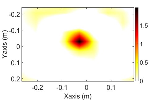
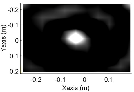
Microwave Imaging, an emerging modality, holds the potential to complement established methods like Magnetic Resonance Imaging (MRI) and Computed Tomography (CT). Its affordability, non-invasiveness, and portability make Microwave Imaging well-suited for early tumor detection. In this study, we used a microwave imaging system using a prototype scanner with two Vivaldi antennas transmitting and receiving signals from 2.5 GHz- 8 GHz. A pyramidal shaped homogeneous wood phantom served as the scanned object. The acquired data from the Vector Network Analyzer (VNA), represented by the S21 parameter on the receiving antenna, was collected for input into the reconstruction algorithm. Filtered Back Projection (FBP) is used as the reconstruction algorithm having a Hann window as the filter for optimal results. Qualitatively, the FBP reconstructed image exhibited smoother quality with clearer edges with decent processing time. In the future, multiple 2D scans at different heights of the object can generate the 3D cross-sectional image by implementing the MATLAB code.

Microwave Imaging detects tumors by discerning variations in permittivity profiles or distributions between normal and abnormal cells. Two prevalent methods for reconstructing images in microwave imaging are the reflection method and transmission method [1]. The reflection method involves utilizing scattered fields captured by multiple receiver antennas. In this approach, the reconstructed image is derived by solving the electromagnetic inverse scattering problem, specifically the object's permittivity profile [2]. Drawbacks include the need for numerous receiver antennas and the computational complexity coming from the non-linear nature of the inverse scattering problem. On the other hand, the transmission method relies on the attenuation profile of electromagnetic waves penetrating the object [1]. This method assumes straight-line or ray-based electromagnetic propagation, resulting in simpler mathematics and a reduced need for receiver antennas compared to the reflection method.

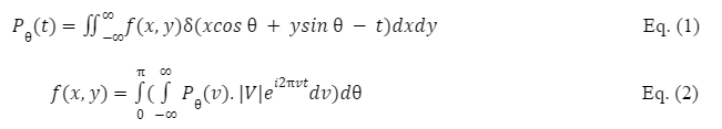
In prior research, a microwave imaging system was simulated in Computer Simulation Technology (CST) software using a straightforward cylindrical phantom as the scanned object [3, 4, 5]. The phantom's image was successfully reconstructed using the transmission method. The formation of a reconstructed image through the transmission method involves employing an algorithm alike to that used in CT scans, focusing on generating the material permittivity distribution of the object. The analytic approach relies on mathematical formulations, offering speed and elegance but lacking the capability to address complex issues such as scattering phenomena. The simplest algorithm within the analytic method is Filtered Back Projection (FBP), where the Fourier Slice Theorem is applied for image formation [6]. The acquired measurement data can be modeled using the Forward Problem, expressed by Eq. (1), commonly known as the Radon Transform. Here, PΘ(t) represents the attenuation profile (assumed to be the S21 parameter in microwave imaging), known as the sinogram, and fx,y represents the 2D image to be reconstructed. The image can be reconstructed from the acquired measurement data by applying the Inverse Problem, as formulated in Eq. (2).

equation


To generate an accurate representation of scatterers within a specific imaging area, the intensity distribution of scattered waves in that area is determined by analyzing the fields received at various antenna locations surrounding the area. A Vivaldi antenna at one end emits electromagnetic waves and another collects the waves that are scattered from the object and this process is continuous for Np antenna positions encircling the imaging area. For each frequency increment (m = 1 to Nf) and from every point (x, y) within the imaging zone, the scattered electromagnetic field (Escat) is calculated. This calculation is based on the S-parameters (Smeas), which are signals measured at each antenna position (n = 1 to Np) around the imaging area. The process of measuring across all antenna locations and frequency increments yields a total of Nf x Np values representing the estimated scattered field at every point within the imaged area used for image reconstruction.

hardware/software tradeoffs: This imaging method and MATLAB code cannot disguise the edges of the object perfectly. Currently, 3D image reconstruction is also not possible as it needs a decent amount of time to write the MATLAB code, but it can be done in future.

Experimental setup:

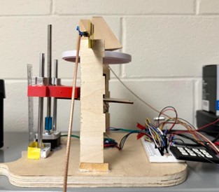
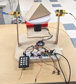
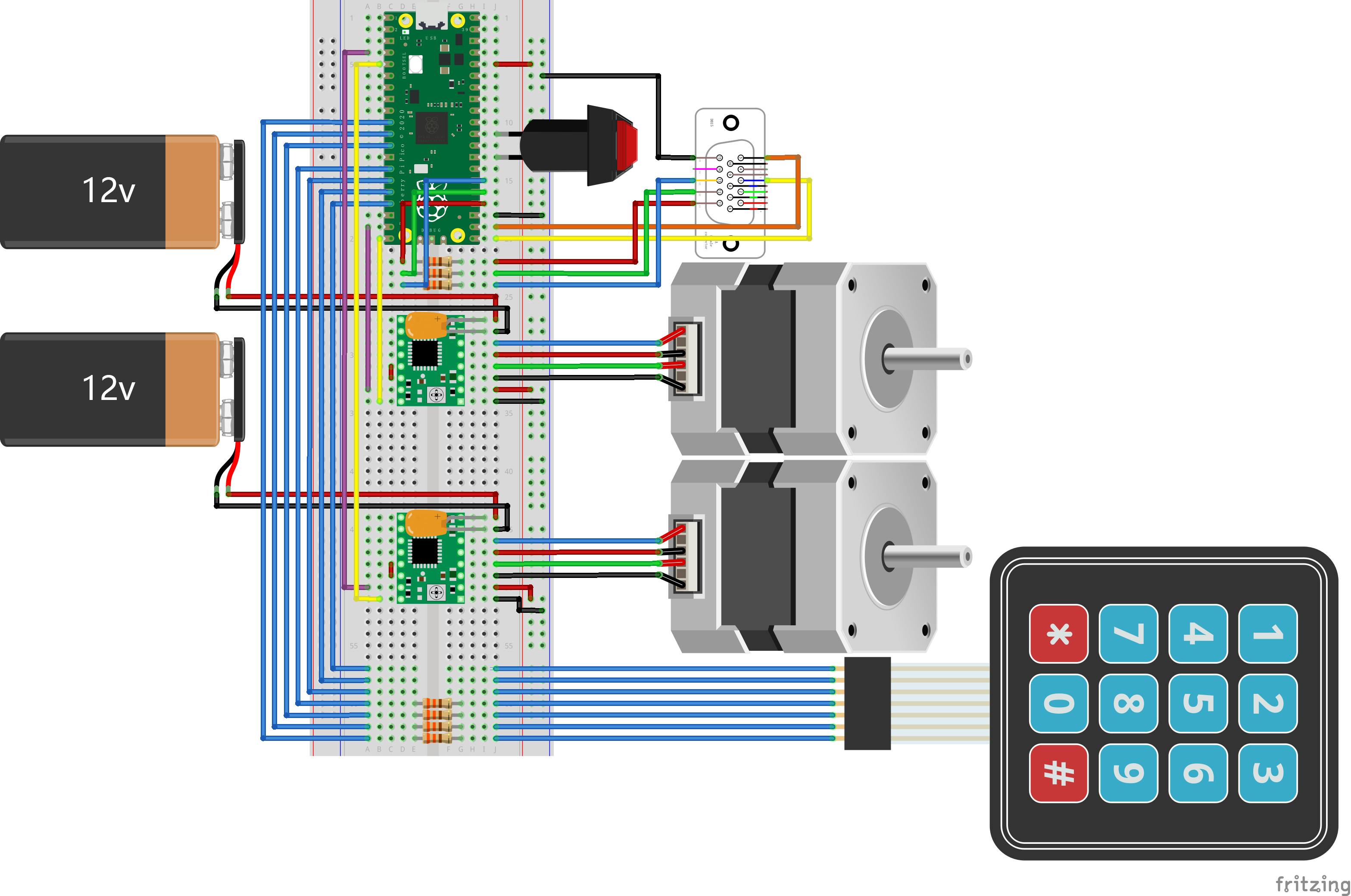
The proposed microwave imaging system comprises two primary components: measurement-oriented hardware and reconstruction-focused software in MATLAB to generate images of scanned objects from acquired measurement data. The hardware component includes two Vivaldi antennas for transmitting (Tx) and receiving (Rx) microwave signals from 2.5 GHz-8 GHz; a Vector Network Analyzer for signal generation and S21 parameter measurement; and a proposed scanner system having various hardware components. The scanner is equipped with step motors and microcontrollers for data acquisition as shown in Fig.1.

To assess the performance of the Filtered Back Projection (FBP) algorithms, a pyramidal shaped wood phantom with a relative permittivity Εr of 2-3 is employed as the material under test (MUT). During measurement, both Vivaldi antennas (Tx-Rx) are positioned 23 cm apart, translating together along the object. The S21 parameter is then acquired from the Vector Network Analyzer at each position. Following the translation process, the antennas are rotated at specific degrees (such as 9 or 18 degrees), and the translation process is repeated until the end of the rotation degree (complete 360-degree scan).
Generic placeholder image
Fig.1. Experimental setup of microwave imaging system with two Vivaldi antennas

Program & Hardware Co-Design

1. Hardware Implementation

a) System Overview

The Microwave Imaging System is engineered with a blend of electronic and mechanical components, each chosen for its role in achieving imaging. The system employs precise control mechanisms, leveraging the capabilities of a powerful microcontroller and dedicated motor drivers to manipulate stepper motors. These motors are responsible for the dual-axis movement required for multidimensional scanning. A user interface, consisting of a keypad and a VGA connector, allows for real-time user interaction and system monitoring. Safety and stability are ensured through the inclusion of capacitors and resistors, which protect against voltage spikes and regulate current. The run switch provides a simple interface for system control, allowing for quick resets or activation of the imaging process.

System Sketch
Fig.2. - Sketch of the Microwave Imaging Hardware System

b) Component Functions

2. Software Implementation

a) Program Overview

The Microwave Imaging System's software is crafted to seamlessly bridge the gap between the intricate hardware controls and the user's operational commands. Developed for the RP2040 microcontroller, the software is responsible for executing precision motor movements, processing user interface interactions, and rendering visual feedback through a VGA output. The multi-threaded application is architected to balance computational demands across the microcontroller's dual cores, ensuring fluid system performance.

b) Program Functionalities

i. User Interface

The user interface of the microwave imaging system is designed to provide a direct and intuitive experience for the user. The UI operates on the principle of conditional rendering, where visual elements on the VGA monitor are updated only when the system state or user input changes. Considering that VGA monitors have a refresh rate of 60 Hz, this approach is crucial to save resources on the microcontroller and maintain a clear and stable image on the VGA monitor.

When the system boots, initialization is performed, which configures the GPIO pins for the keyboard interface. An internal pull-down resistor is activated to ensure that keyboard input remains in a defined low state until a key is pressed. This setting prevents spurious signals that could cause false input detections. The detector_keypad() function is essential for scanning the keyboard. It uses an efficient matrix scanning algorithm to minimize scanning time by quickly identifying active keys. The software then interprets the corresponding keycode, which indicates subsequent UI updates or control commands.

Rendering the UI is handled by the draw_UI() function, which intelligently redraws only the necessary parts of the screen. For example, it avoids redrawing the entire screen for each frame and instead updates only the areas that have changed, such as menu transitions or parameter adjustments. This selective update is essential to reduce visual flicker and ensure users always see the display clearly.

ui
Fig.3. - User Interface when Running

ii. Motor Control

The software's motor control subsystem is engineered to translate user inputs into precise mechanical movements. The RP2040 microcontroller directs the stepper motors through the A4988 drivers, taking care to produce the exact number of steps required for the desired rotation angle or vertical movement.

In manual control mode, the operator can input specific values for the desired movement. The software computes the necessary steps and executes the motion by toggling the STEP and DIR pins of the motor drivers accordingly. The rotation is managed by the protothread_serial() function, which also monitors for a stop condition, ensuring that the system halts the rotation at the correct time. For automated scanning, the software follows predefined sequences that are orchestrated through a series of steps and intervals. These sequences are designed to cover the entire scanning area systematically. The software takes into account the steps per revolution and the interval timing to create a consistent and repeatable scanning pattern. This automation is critical for achieving uniform data collection across different scanning sessions.

The challenge in motor control was not only to achieve this precision but also to integrate it smoothly with the UI updates. The software ensures that motor operations do not interfere with the user's ability to interact with the system or the visual feedback provided by the UI. This is managed by careful thread scheduling and prioritization, where UI responsiveness is maintained alongside ongoing motor operations.

First GIF
Rotation
Second GIF
Lift

c) Challenges

In developing the software for the Microwave Imaging System, several aspects presented notable challenges, requiring careful planning, precise coding, and extensive testing to ensure both functionality and reliability.

3. Replicability of the Project

In its current form, the documentation and code provided for the Microwave Imaging System offer a solid foundation for another individual or team to recreate or build upon this project. The software implementation, especially, is detailed with clear explanations of both the user interface and motor control logic. However, the replicability of the project also depends on a few factors:

4. References

The development of the software for the Microwave Imaging System was influenced by external resources and previous work.

5. Unsuccessful Attempts

During the development phase, some ideas and implementations were explored but ultimately not incorporated into the final design:

6. Summary

The software of the Microwave Imaging System deftly combines detailed control logic with a responsive UI, all while managing the computational constraints of the RP2040 microcontroller. By updating the UI only when changes occur and by synchronizing motor movements with user commands, the system achieves a balance between operational efficiency and user engagement. The software's design ensures that the system is robust when running, user-friendly for operation, and ready for future enhancements.

Results

The rotational process was adjusted to a 9-degree rotation, yielding 40 sets of rotational data at 26 frequencies between 2.5 GHz-8 GHz. These data were transformed into a 26x40 matrix which served as the input for the image reconstruction algorithm. The 2D image obtained from a center cross section of a pyramid solid wood phantom is depicted in Fig. 3. This image was reconstructed using FBP which uses a Hann window filter. The resulting image was both qualitatively and quantitatively analyzed and is displayed in black and white color format in Fig.4. The FBP created an image around 500x500 pixels in spatial resolution. Areas outside the square in the FBP image likely represent air distribution, making the FBP image qualitatively clearer. FBP also boasts a faster processing time due to its simpler algorithm and available MATLAB code. The images were reconstructed in approximately 5 seconds with decent accuracy when compared with the dimension of the original object.

ui
Fig.4. 2D- Reconstructed image of pyramid wood phantom (color)
ui
Fig.5. 2D-Reconstructed image of pyramid wood phantom (black and white)

Conclusion

In our study, we deployed a microwave imaging system featuring a prototype scanner with two Vivaldi antennas operating between 2.5 GHz and 8 GHz frequencies. We scanned a pyramidal shaped, homogeneous wood phantom, acquiring data through the S21 parameter from a Vector Network Analyzer (VNA) for image reconstruction using Filtered Back Projection (FBP) with a Hann window filter. Our system's experimental setup involved a comprehensive hardware and software design. The hardware included two Vivaldi antennas, a Vector Network Analyzer, and a scanner system with step motors and microcontrollers for precise data acquisition. The system's software, developed for the RP2040 microcontroller, managed motor movements and processed user interface interactions. Challenges encountered during development included complex UI logic, precision in motor control, and synchronization between threads. Despite these challenges, the project is replicable with detailed documentation and a clear guide on the software-hardware interaction.

The results of our study are promising. The system's rotation was adjusted to a 9-degree increment, providing a comprehensive data set that was processed into a 26x40 matrix. This matrix served as the input for the FBP algorithm, resulting in a detailed 2D image of the phantom's cross-section. The FBP algorithm, with its simple design and rapid processing capability, generated images within approximately 5 seconds, demonstrating decent accuracy compared to the original object's dimensions.

The study underscores the potential of Microwave Imaging in medical diagnostics. Its ability to produce clear images of objects, coupled with the system's design and efficient processing algorithms, highlights its applicability in early tumor detection and other medical imaging needs. The success of this prototype scanner and its algorithms, particularly FBP, opens doors for further research and development in this field. Future work could focus on enhancing image resolution, expanding to 3D image reconstruction, and refining the system's hardware and software components for more complex applications. This study serves as a significant step towards establishing Microwave Imaging as a viable, cost-effective alternative in medical imaging technology.

The MATLAB coding for image reconstruction is developed by us and not someone else code. The project work is publishable in some of the microwave conferences such as IEEE APS– URSI symposium and IEEE Radio and Wireless Week.

Team

Generic placeholder image

Zehao Li

zl823@cornell.edu

Generic placeholder image

Kapil Gangwar

kg434@cornell.edu

Appendix A

The group approves this report for inclusion on the course website.

The group approves the video for inclusion on the course youtube channel.

Appendix B

Reference

  1. Larsen, L. E. and J. H. Jacobi, “Medical applications of microwave imaging,” IEEE Microwave Theory and Techniques Society, New York, 1995.
  2. Chew, W. C. and Y. M. Wang, “Reconstruction of two-dimensional permittivity distribution using the distorted born iterative method,” IEEE Transactions on Medical Imaging, Vol. 9, No. 2, June 1990.
  3. M. N. Akinci et al., “Qualitative Microwave Imaging With Scattering Parameters Measurements,” in IEEE Transactions on Microwave Theory and Techniques, vol. 63, no. 9, pp. 2730-2740, Sept. 2015.
  4. Elevani, D., R. Ramadhan, D. T. Parastika, and Basari, “Evaluation of Algebraic Reconstruction Technique algorithm for microwave imaging,” 2016 Progress In Electromagnetic Research Symposium (PIERS), 587–591, Shanghai, China, Aug. 8–11, 2016.
  5. Aprilliyani, R., R. G. Prabowo, and Basari, “Comparison analysis between SART and ART algorithm for microwave imaging,” 2017 Progress In Electromagnetics Research Symposium — Fall (PIERS — FALL), 1674–1678, Singapore, Nov. 19–22, 2017.
  6. Kak, C. and M. Slaney, Principles of computerized Tomographic Imaging, IEEE Press, New York, 1988.


Project Code

Project Repository on GitHub