Autonomous Luggage Following System
2023 Fall ECE5730 Final Project by Yuqiang Ge (yg585) and Yiyang Zhao (yz2952)
Project Video
Project Introduction
Description
The system is aimed at creating a smart and autonomous luggage that can effortlessly track and follow its user, providing convenience in airports, train stations, or any travel environment, easing the burden of carrying heavy luggage. This system can track the user’s direction and the distance between the user and the luggage.
Overview
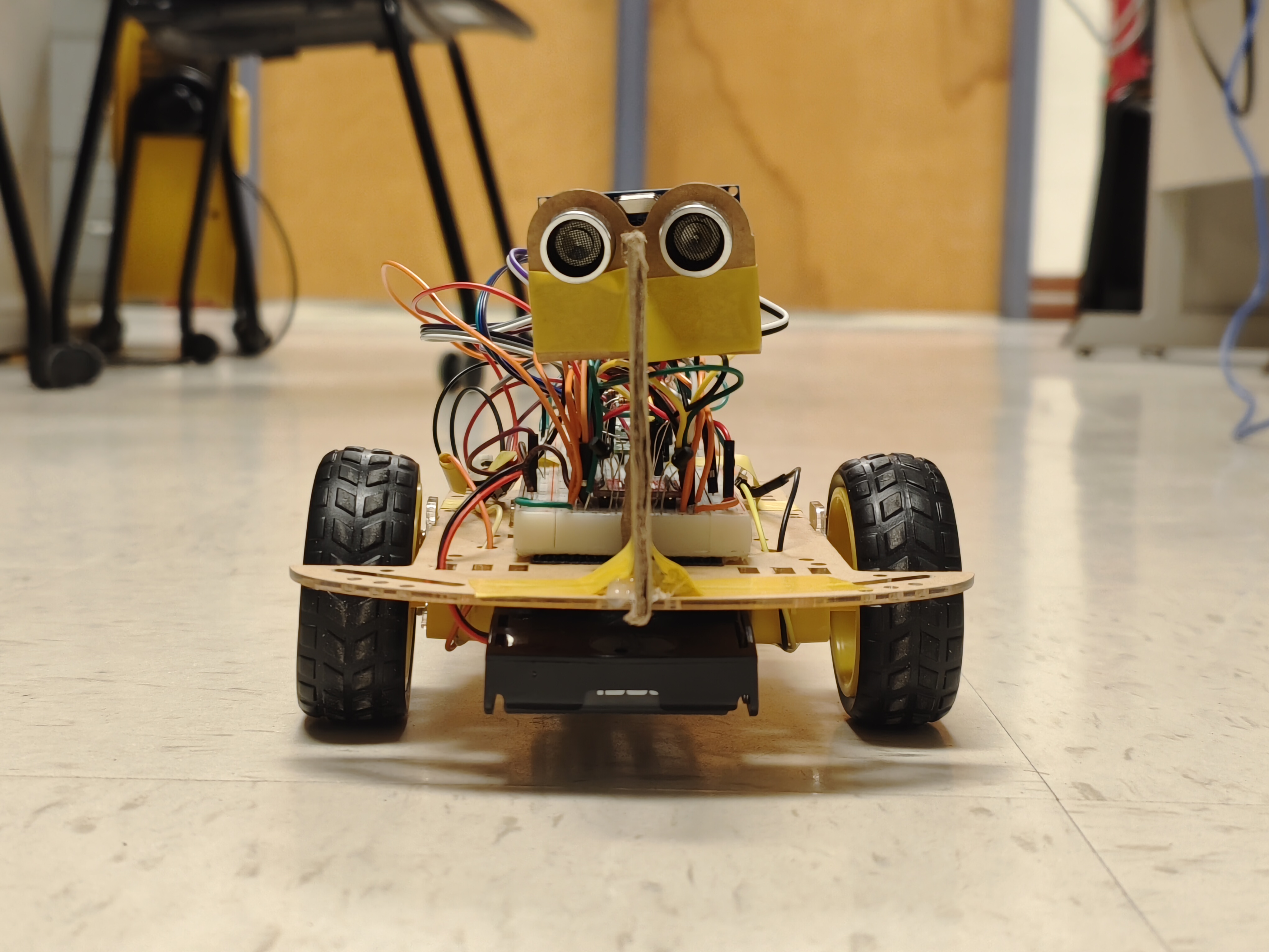
In this project, we employ a robot car to simulate luggage movement, thereby facilitating our development process. When transitioning the system to the actual luggage, a simple motor replacement with increased power is all that is required for enhancement.
Directional determination is achieved through the use of a pair of infrared receivers. In instances where the robot car loses its direction or is powered on, it autonomously rotates while actively scanning for infrared signals. A centrally positioned paperboard separates the two infrared receivers, enabling them to discern direction based on signal intensity. Additionally, an infrared LED is integrated into the user's equipment, emitting infrared light detectable by the robot's infrared receivers.
The system is further equipped with a pair of ultrasonic sensors, functioning similarly to the infrared sensors. One sensor transmits signals, while the other receives, enabling the calculation of distance between the sensor and objects in front based on signal emission and reception times.
The robot car's motion system comprises two DC motors and a motor controller. As DC motors cannot directly interpret PWM signals, the utilization of a motor controller is logical for modulating motor power. This modulation allows for precise control of the motors' speed, enhancing the overall functionality of the system.
High Level Design
Rationale and Sources of Project Idea
As people travel more and more these days, there's a growing need for a new kind of luggage system that can automatically follow travelers. This kind of system would be incredibly useful, especially in crowded places like train stations and airports.
Imagine if your suitcase could follow you on its own. You wouldn't have to worry about dragging heavy bags anymore. You could freely make phone calls, check information boards, or take care of your children without being distracted by your luggage. Such a suitcase would make traveling much easier.
For people with limited mobility, an automatically following suitcase would be a huge help. Some people might find it difficult to carry luggage by themselves and relying on others can make them feel uncomfortable. But with a suitcase that can autonomously follow them, they can travel more freely and experience greater independence and autonomy. This technology also lessens the burden for caregivers, making travel easier and more enjoyable for everyone.
Background Knowledge
1. Ultrasonic Ranging
Ultrasonic ranging is a technique that uses ultrasonic waves, which are sound waves with frequencies higher than the human audible range, typically above 20 kilohertz, to measure distances.
The process starts with an ultrasonic transmitter emitting high-frequency sound waves. These waves travel through the air and, upon encountering an object, are reflected back towards the source. This reflection creates echoes that are captured by an ultrasonic receiver, often the same device as the transmitter.
The key to measuring distance lies in the time difference between when the ultrasonic waves are emitted and when the echoes are received. This time lapse is crucial as it represents the total time taken for the waves to travel to the object and back. Since the speed of sound in air is known, approximately 343 meters per second, this time difference can be used to calculate the distance to the object. The distance is computed using the formula: Distance = (Speed of Sound × Time) / 2.
2. Infrared Phototransistor
An infrared phototransistor is a semiconductor device designed to respond specifically to infrared light (IR). At its core, it functions similarly to a standard transistor but with a significant sensitivity to infrared light.
The operation of an infrared phototransistor begins when it is exposed to infrared light. Infrared light interacts with the semiconductor material of the phototransistor. When IR photons strike the material, they impart energy to the electrons, elevating them to a higher energy state and thereby creating charge carriers.
These charge carriers increase the conductivity of the semiconductor material. In practical terms, this translates to a change in the current flowing through the transistor. The amount of current generated is directly proportional to the intensity of the incident IR light. Thus, the phototransistor effectively converts varying IR light intensities into corresponding electrical signals.
logical Structure
Our devised system exhibits three different operational states:
Target Loss Mode: If the target is lost, the system stops moving briefly and then rotates. During this time, the system consistently tries to find the target again. Once the target reappears, indicated by the detection of the infrared signal, the robotic car continues its tracking.
Following Mode: Our design focuses on tracking a specific target by detecting an infrared signal, analyzing signal strength differences to determine the target's lateral position, and then dynamically adjusting the duty cycle of the PWM for the two motors to enable precise turns and straight-line movement.
Obstacle Avoidance: The system incorporates an obstacle avoidance function for autonomous luggage tracking in complex environments. When it detects an obstacle in front of itself, the car quickly stops moving. After a brief pause, it rotates, trying to assess potential targets from the left, right, or rear perspectives.
Tradeoffs
Tradeoffs were a critical aspect of our project, especially with a focus on cost-effectiveness. Ranging is relatively simple, we could have used ultrasonic ranging, but how to get the direction is more complicated. Ultimately, after considering several alternatives, we finally decided on a solution with two infrared receivers.
Initially, we contemplated using Ultra-Wideband (UWB) chips. UWB is good for indoor localization, it can be used to get the direction and distance to the target. However, their cost was a significant deterrent; each chip costs around twenty dollars, requiring a total of forty dollars for two. Additionally, the lack of support for the Raspberry Pi Pico presented a major challenge, as there were no readily available libraries for using UWB chips with the Pico.
Our second option involved the use of a servo mechanism. The idea was to mount a directional infrared receiver on a servo, using its rotational movement to determine the direction of a person, akin to a radar system. Upon experimentation, we found that this approach had limitations. The servo's rotation speed and the system's responsiveness were not adequate for effective person-following, resulting in sluggish reactions and imprecise positioning. Furthermore, as a moving mechanical part, the servo lacked the stability and durability. This option was also more expensive compared to our final choice.
We also explored the possibility of sound localization using microphones. This method would have required three microphones, each costing seven dollars, elevating the overall cost. Additionally, the complexity of the algorithm needed for sound localization and its usability posed significant challenges. The necessity for a person to carry a sound source and the susceptibility to noise interference further detracted from the viability of this approach.
In contrast, the dual infrared receiver setup offered a more cost-effective and technically feasible solution. It provided a balance of performance, stability, and affordability, addressing our project requirements more effectively than the alternatives we considered.
Program and Hardware Design
Program Details
Our system has three primary functions: motion control, infrared positioning, and ultrasonic ranging. These tasks are encapsulated within the proto thread, arranged and synchronized via semaphores to maintain a coherent order. The sequential execution of the three threads follows the prescribed sequence: ultrasonic ranging -> infrared positioning -> motion control. This structured sequence guarantees the seamless operation of system functionalities. In the main program, what we mainly do is some initialization work. The intricate details of each thread are expounded below:
1. distance_measure
Objective: This thread is dedicated to the precise measurement of distances using ultrasonic sensors.
Execution: In this process, the measure function determines the distance between the robot car and the object in front of it. Following this, a condition is checked: if the measured distance is less than a specified threshold (in this instance, 25cm), the 'stop' variable is set to 1; otherwise, it is set to 0, as illustrated below. This result is then sent to the post for further handling. The thread subsequently activates the infrared detection thread using the PT_SEM_SIGNAL function.
measure();
if ( distance < 25){
    stop = 1;
}
else{
    stop = 0;
}
2. infrared_detection
Objective: Focused on the accurate determination of the target's position through infrared signal detection.
Execution: The voltage across infrared receivers reflects the intensity of infrared signals. To measure this intensity, we employ the analog-to-digital converter (ADC) in the Raspberry Pi Pico. The first step is to read ADC values, followed by a comparative analysis to determine the target's position—whether it is in the front left or right:
direction_differece = adc_values[0] - adc_values[1];
if (direction_differece > 0 ){
	is_left = 1;
}
else {
	is_left = 0;
}
Following this determination, we calculate the absolute value of direction_difference, and the motor control thread is activated for further processing.
3. motor_control
Objective: Responsible for performing the movement of the system based on the data from distance_measure and infrared_detection threads.
Execution: In this process, we start by using direction_difference as feedback input for the Proportional-Integral-Derivative (PID) controller in this thread. The pid_iterate function is then run once to control the motor response. Afterward, a conditional check verifies whether is_left is equal to 1. If this condition is met, the left motor is adjusted to generate a lower PWM duty cycle compared to the right one, and conversely for the right motor.
Code Structure
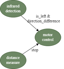
The diagram explains how the code's organizational structure works. After the other two tasks finish their calculations, motor control incorporates the data. Infrared detection establishes the values for 'is_left' and 'direction_difference,' while distance measurement sets the stop flag. Using these assigned values, motor control then manages the motion of the robot car.
4. State Machine
Furthermore, within the motor_control and distance_measure threads, there are two distinct state machines. The former performs the rotation of the robot car in cases such as target loss or obstacle avoidance, while the latter serves the purpose of filtering ultrasonic ranging data.
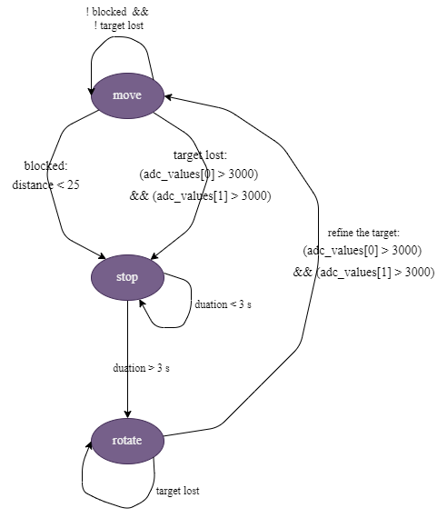
State Transition of Motion for Robot car
The finite state machine illustrates the three motion states of the robotic car and their transition conditions. In normal situations, the system smoothly tracks the specified target. However, if the target is lost or an obstacle is encountered, the car transits to a stationary state, waiting for a predefined duration. After this stationary period, the car resumes rotation to try to regain the target. Once the target is successfully detected, the car returns to its usual tracking behavior.
Below is the implementation of this state machine based on the figure shown above.
while(1) {
        PT_SEM_WAIT(pt, &motor_semaphore);
        pid_iterate();
        if (!rotate) {
            if (stop == 0){
                counter_stop = 0;
                if ((adc_values[0] > 3000) && (adc_values[1] > 3000)){
                    counter_stop2++;
                    if(counter_stop2 >=100) {
                        rotate = 1;
                    }
                }
                else if (is_left == 1){
                    counter_stop2 = 0;
                    pwm_set_chan_level(slice_num_1, PWM_CHAN_B, control);
                    pwm_set_chan_level(slice_num_1, PWM_CHAN_A, control-pid.output);
                }
                else{
                    counter_stop2 = 0;
                    pwm_set_chan_level(slice_num_1, PWM_CHAN_B, control-pid.output);
                    pwm_set_chan_level(slice_num_1, PWM_CHAN_A, control);
                }
            }
            else{
                pwm_set_chan_level(slice_num_1, PWM_CHAN_B, 0);
                pwm_set_chan_level(slice_num_1, PWM_CHAN_A, 0);
                counter_stop++;
                if(counter_stop >=500) {
                    rotate = 1;
                }
            }
        }
        else {
            if((adc_values[0] > 3000) && (adc_values[1] > 3000)){
                gpio_put(14, 1);
                gpio_put(15, 0);
                gpio_put(16, 0);
                gpio_put(17, 1);
                pwm_set_chan_level(slice_num_1, PWM_CHAN_B, 4000);
                pwm_set_chan_level(slice_num_1, PWM_CHAN_A, 4000);
            }
            else {
                rotate = 0;
                counter_stop2 = 0;
                gpio_put(14, 1);
                gpio_put(15, 0);
                gpio_put(16, 1);
                gpio_put(17, 0);
                pwm_set_chan_level(slice_num_1, PWM_CHAN_B, 0);
                pwm_set_chan_level(slice_num_1, PWM_CHAN_A, 0);
            }
        }

        PT_SEM_SIGNAL(pt, &distance_semaphore);

        // Yield for 5 ms
        PT_YIELD_usec(5000) ;
    }
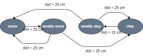
State Transition of Filter for the Data from Ultrasonic Sensor
This illustration demonstrates the use of finite state machines for filtering data from the ultrasonic sensor on a robot car. To address occasional noise detection that could cause abrupt pauses, we apply a filtering mechanism, similar to the button filtering used in lab 1. The stop flag is set only after two consecutive detections; otherwise, the system returns to the motion state. Likewise, if no obstacles are detected in two successive instances, the robot car continues moving forward; otherwise, it goes back to the stationary state.
5. PID Controller
We incorporated PID controller into our system, obtaining insights from lab 3. The PID controller uses the difference in infrared signals detected by two infrared receivers as feedback input, regulating the power output of the two motors differentially. This control mechanism enables precise control over the robotic car, allowing it to closely follow the target and execute smooth movements.
Hardware Details
Circuit Diagram
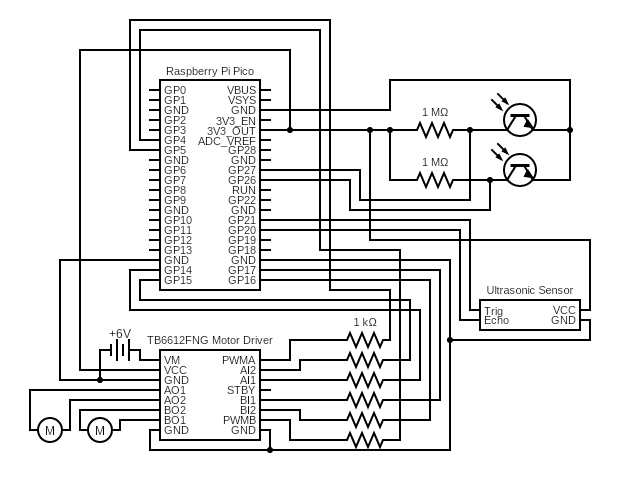
In this project, the Raspberry Pi Pico serves as the main controller controlling three peripheral sub-circuits: the infrared phototransistor circuit, the ultrasonic ranging circuit, and the motor control circuit. Each of these sub-circuits plays a pivotal role in the operation of the system, and they are analyzed in detail below.
1. Ultrasonic Ranging Circuit:
The ultrasonic ranging circuit incorporates an HC-SR04 Ultrasonic Sensor, which features four pins. The Trig pin is connected to GPIO 21 pin on the Pico and is used to send out a pulse. The Echo pin, connected to GPIO 20 pin on the Pico, is responsible for receiving the echo of the pulse after it bounces off an object. The duration between the Trig pulse and the Echo reception allows Pico to calculate the distance to the object by using the speed of sound.
2. Infrared Phototransistor Circuit
The infrared phototransistor circuit is constructed by serially connecting a 1 MΩ resistor with an infrared phototransistor. The purpose of this circuit is to detect the presence and intensity of infrared light. When infrared light shines upon the phototransistor, it causes the device to conduct, resulting in a drop in voltage across the phototransistor. The Raspberry Pi Pico is configured to measure this voltage drop using ADC (GPIO 26 and GPIO 27). As the phototransistor conducts in the presence of infrared light, the ADC reading decreases, providing a digital signal indicative of the light intensity.
3. Motor Control Circuit
The motor control circuit is centered around the TB6612FNG motor driver. The VM pin of this driver is connected to a 6V power supply, which powers the motors. The AIN1, AIN2, BIN1, and BIN2 pins are interfaced with GPIO pins on the Pico, determining the direction of the motors' rotation. The PWMA and PWMB pins receive PWM signals from the Pico, which regulate the speed of the motors by adjusting the duty cycle of the PWM signal. The motor outputs, A01, A02, B01, and B02, are connected to the terminals of two motors, which are driven by the motor driver based on the control signals provided by the Pico. The control function of TB6612FNG is shown in the table below
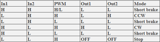
Control Function
Things We Tried
After deciding to use infrared receivers for our project, our initial approach involved using a directional infrared receiver mounted on a rotating servo. We started with a VS1838B infrared receiver that could decode signals emitted by a standard remote control. This allowed us to use any remote as an emitter. Although this method was effective in eliminating interference from other infrared noise, it didn't provide us with the infrared intensit , which resulted in suboptimal tracking performance. We realized that obtaining the intensity of the infrared signal was crucial, so we switched to an infrared phototransistor. However, our experiments showed that the servo-based solution was inadequate. The direction determined was not accurate enough, and the speed of updating the direction was too slow.
We then moved to a new plan that involved using two infrared receivers with a partition between them. We implemented a PID control algorithm to track the target by using the difference in infrared intensity between the two receivers. To enhance the reception of the infrared intensity and make the difference between the two sides more obvious, we did some experiments.
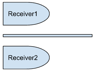
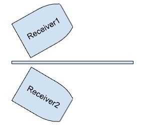
Two Receivers
One of the challenges was determining the optimal resistance for the series circuit with the phototransistor. Due to the small current flowing through the phototransistor, we tested many different resistor values. Eventually, we found that 1 MΩ provided a noticeable difference in the ADC readings, even when the infrared source was at a distance.
We also encountered a limitation due to the narrow receiving angle of the infrared phototransistors, which was approximately 45 degrees. To address this, we attempted a setup with four infrared receivers, with two parallel receivers on each side facing slightly different angles. This configuration expanded the effective angle of reception.
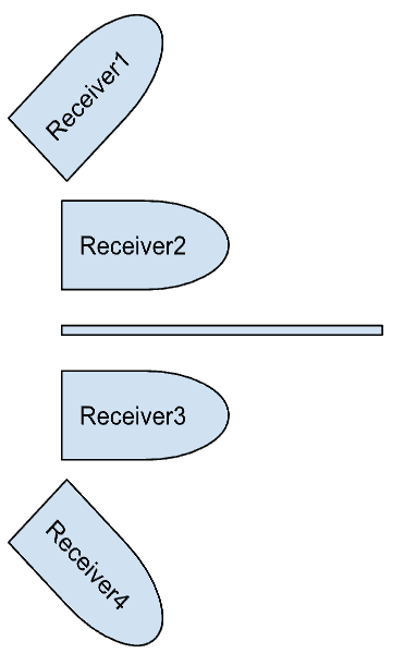
Four Receivers
Despite this adjustment, we faced another issue. The intensity of the infrared was strongest when the emitter was directly in front of the receivers and weakest when it was in between them, leading to poor PID control.
Our final solution was to modify the phototransistors to widen their reception angle. By sanding down the lens-like tip of the phototransistor, we effectively increased the angle of reception. After several tests, we found that the modified phototransistors could still receive signals at angles greater than 70 degrees, significantly improving our tracking system's performance.
Two flattened receivers
Results
Testing Results
We conducted thorough testing on all the hardware components utilized in our project. Initially, we wrote simple program to test the motor driver, examining its rotational directions and the ability to adjust speed through pulse-width modulation (PWM). We observed that our two motors did not have identical speeds at the same PWM duty cycle, which could be attributed to slight variations in hardware parameters during manufacturing. Therefore, we calibrated the motors to synchronize their speed.
Additionally, we created program to test the ultrasonic ranging module. The procedure involved sending a 10-microsecond pulse to the Trig pin and waiting to receive the echo to calculate the distance. This module proved to be relatively straightforward and functioned properly without issues.
The most crucial aspect of our hardware testing was to analyze the waveforms from the infrared receivers. Assessing the waveform is essential to determine if the infrared receivers are functioning correctly.
The following figure shows the waveform of the signal received by the decoder receiver on an oscilloscope. Since we could not get the infrared intensity, we discarded this solution.
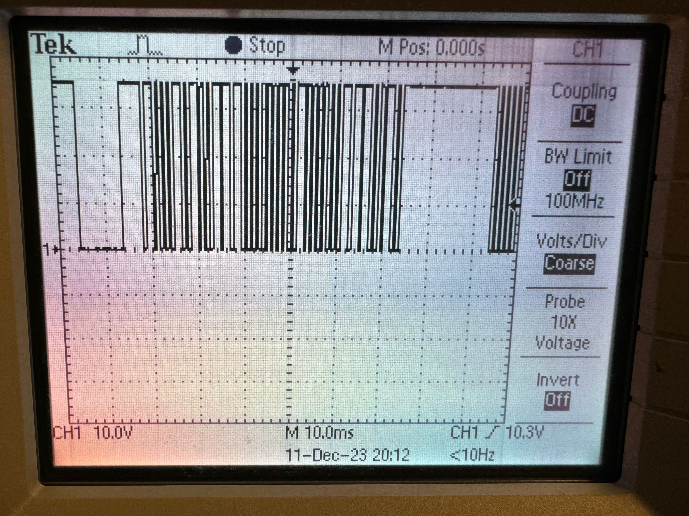
Decoder Receiver Waveform
The following figure shows the waveform of the voltage across the infrared phototransistor on an oscilloscope after receiving an strong infrared signal.
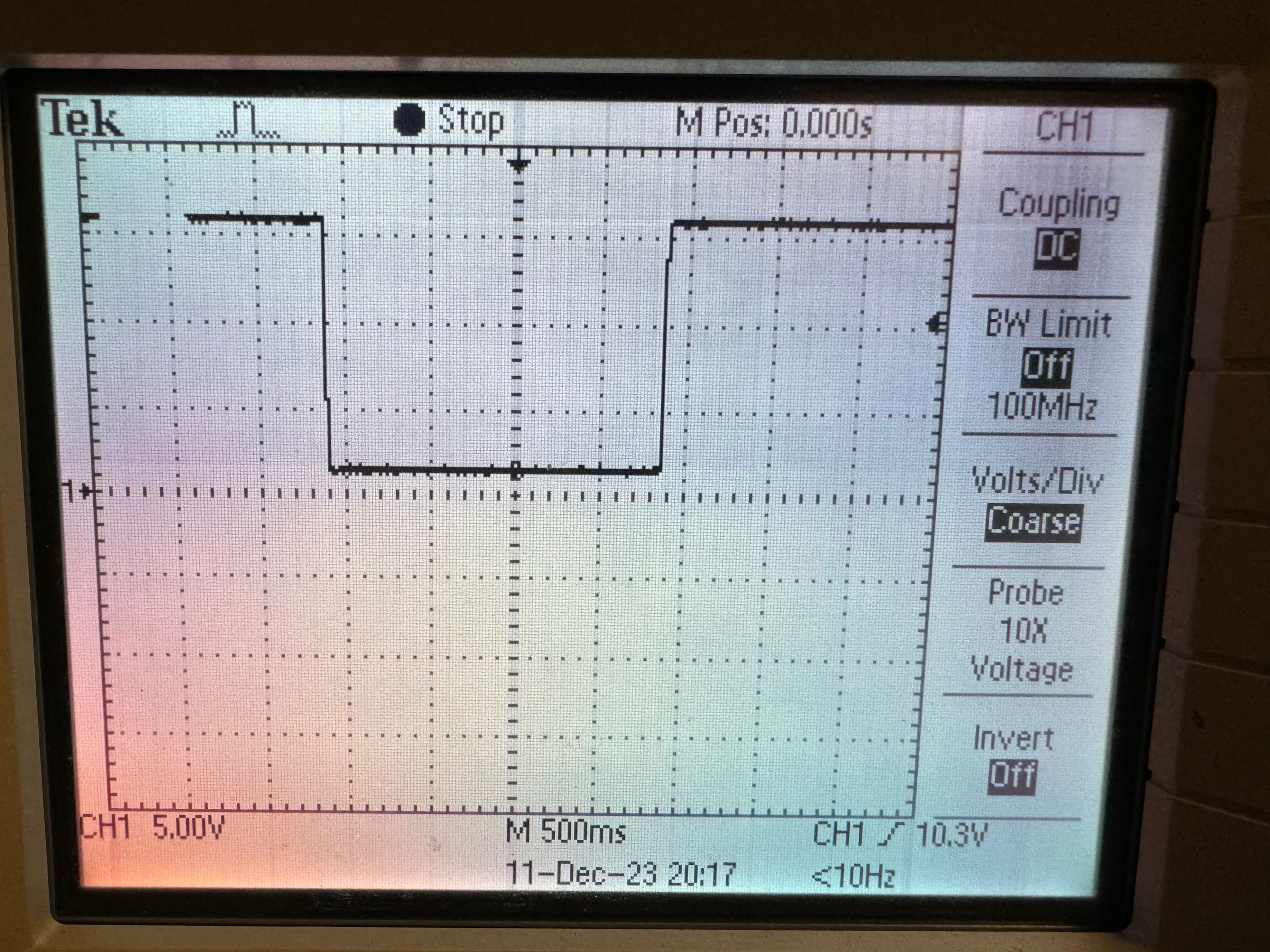
Infrared Phototransistor Voltage (Close to the Infrared Emitter)
The following figure shows the waveform of the voltage across the infrared phototransistor on an oscilloscope after receiving a signal from a long-distance infrared emitter(about 5 meters).
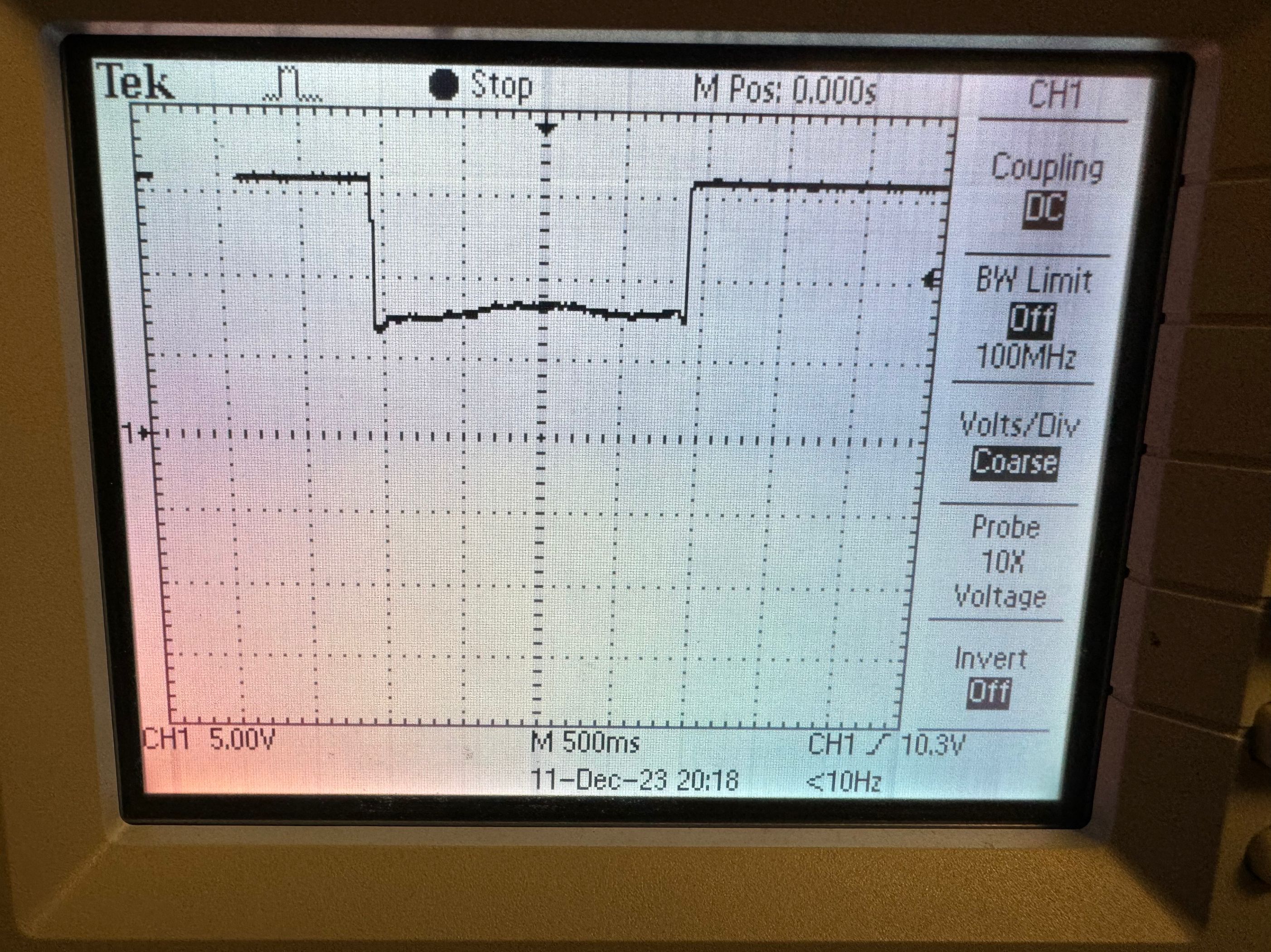
Infrared Phototransistor Voltage (About 5 Meters from the Infrared Emitter)
The following figure shows the waveform of the signal received by the infrared phototransistor when the infrared emitter is directly in front of the two infrared phototransistor receivers.
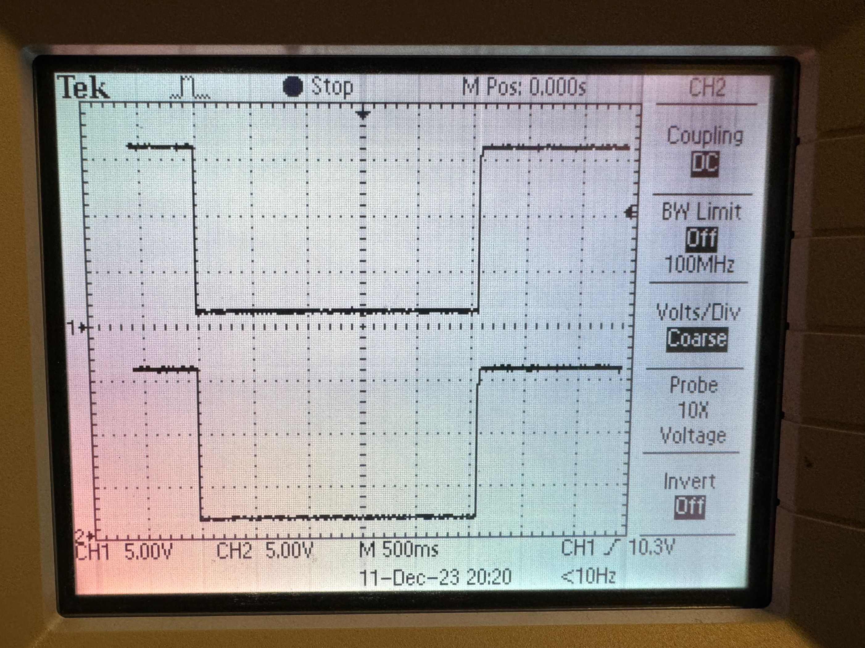
Waveforms of two Phototransistors (Front Emitter)
The following figure shows the waveform of the signal received by the infrared phototransistor when the infrared emitter is on one side of the two infrared phototransistor receivers.
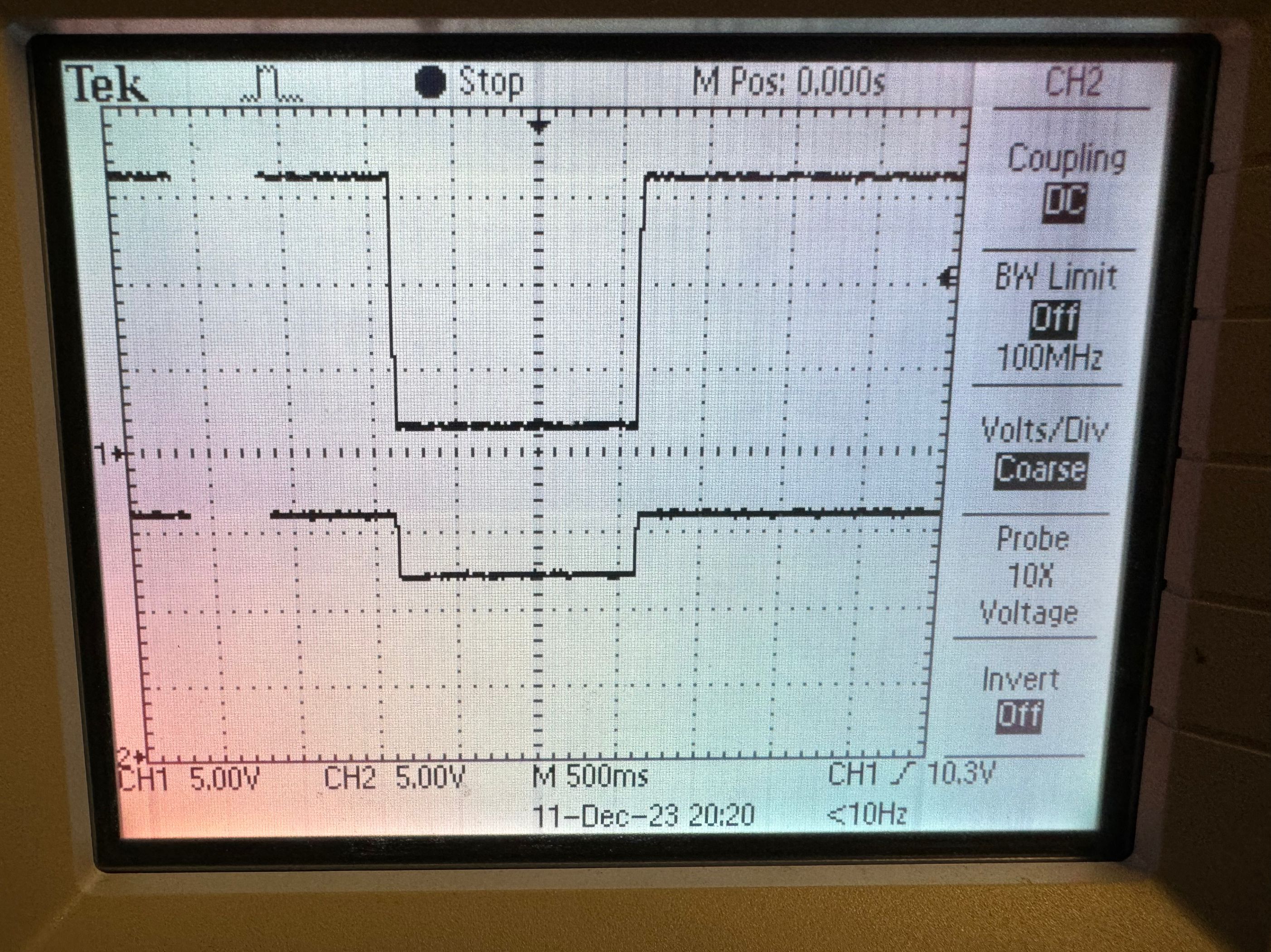
Waveforms of two Phototransistors (Side Emitter)
The following figure shows the ADC's readings for two phototransistor voltages when the emitter is directly in front of them.
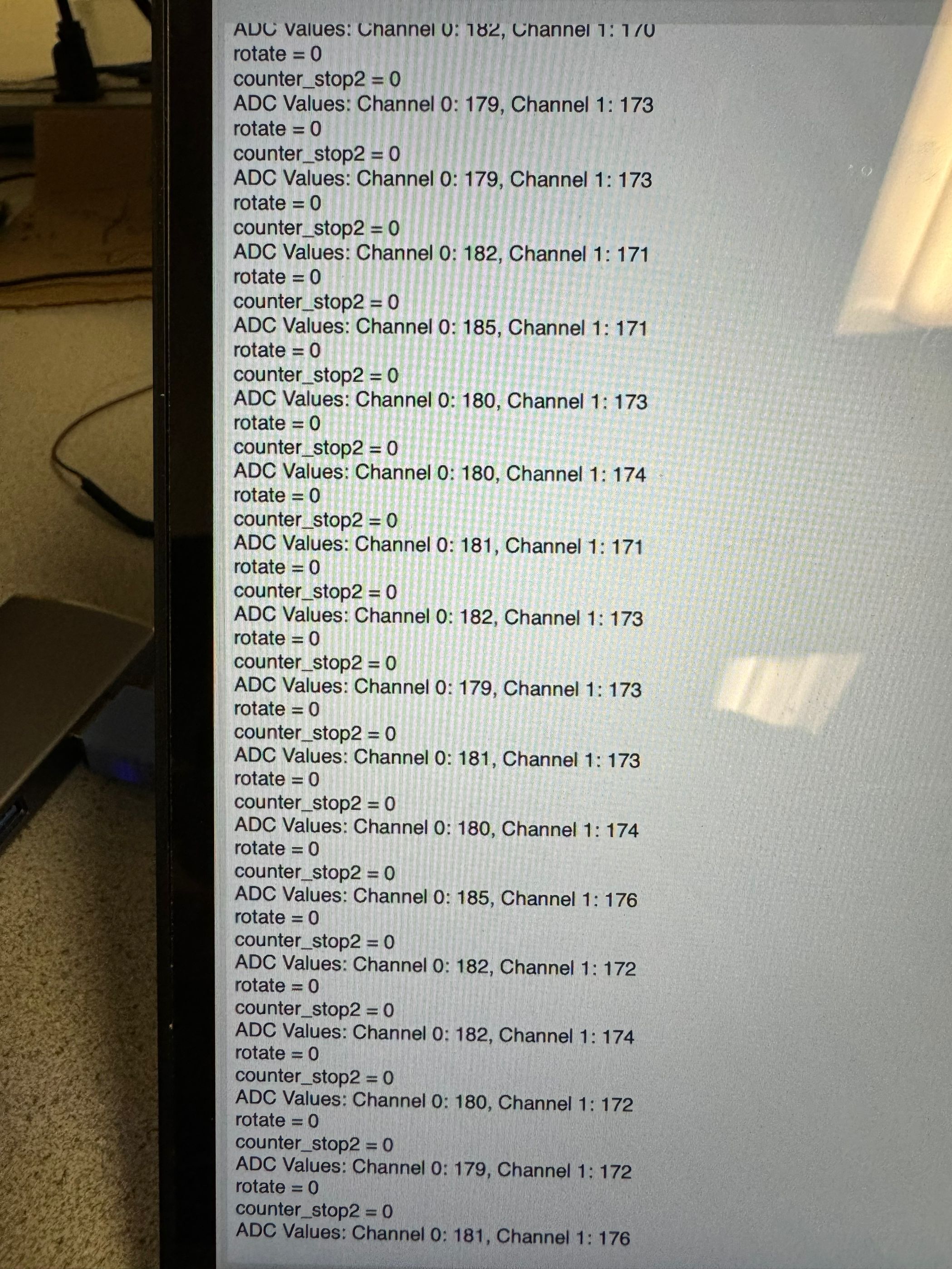
Waveforms of two Phototransistors (Front Emitter)
The following figure shows the ADC's readings for two phototransistor voltages when the emitter is on one side.
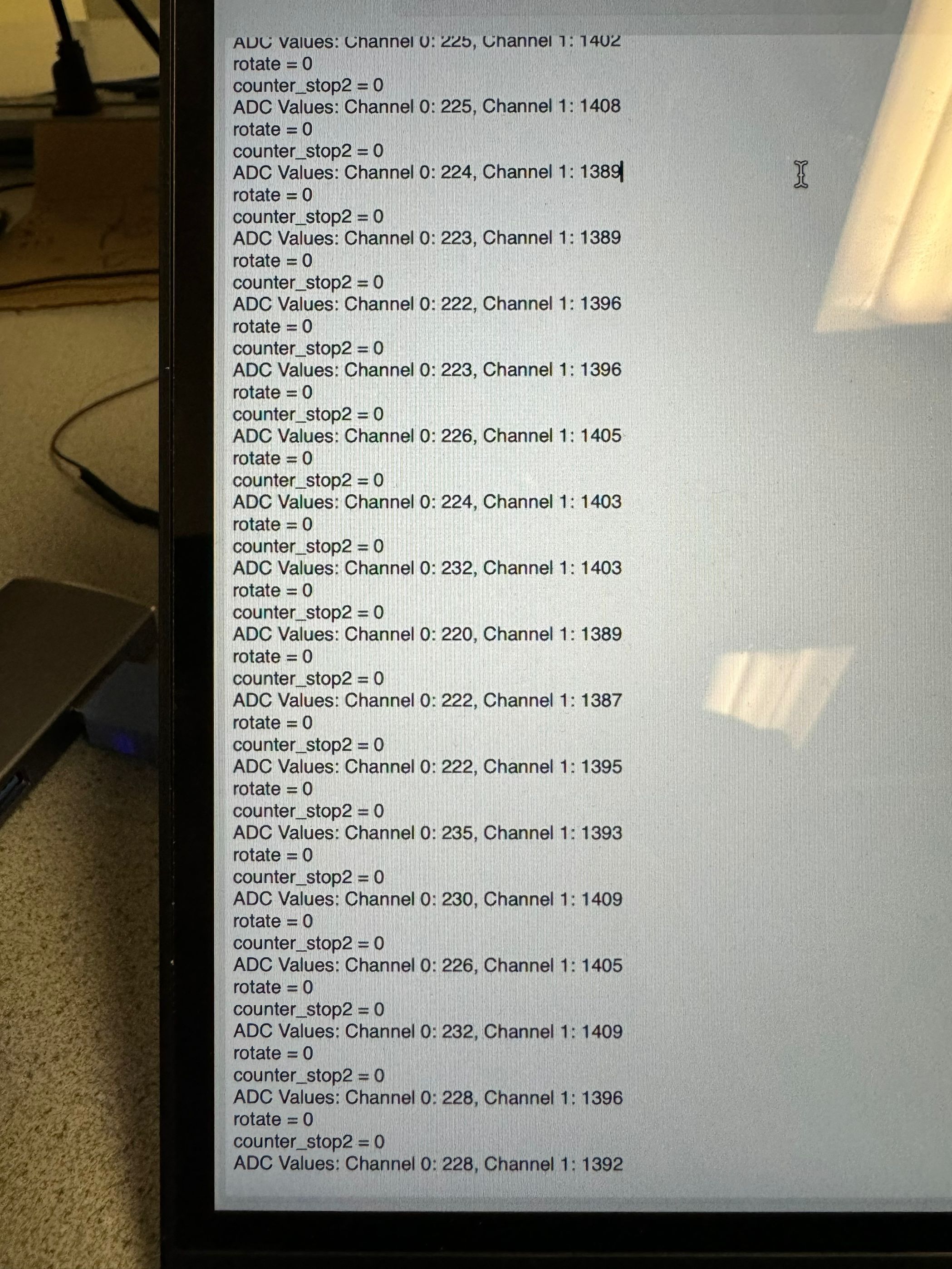
Waveforms of two Phototransistors (Side Emitter)
The above tests prove that our design works. We can perform PID control using the difference of two ADC readings.
Speed of Execution
In examining execution speed, it's important to highlight that our design is not significantly affected by calculation speed. Thus, during development, we did not pay much attention to the speed of execution and did not heavily prioritize optimizing the code from the perspective of execution speed.
Accuracy
During our experimentation, we faced a notable challenge: a part of our robot car sustained damage, causing an uneven speed between the two wheels. Although we provide the same power to the motors, the car cannot move straightly. Despite this mechanical issue, the robot car demonstrates impressive accuracy in the demonstration by effectively tracking the target and staying on a straight trajectory.
The system's resilience and precision come from its robust design, enabling it to compensate for mechanical imperfections and navigate accurately along the intended path despite physical flaws. This underscores the system's capability to perform precisely even in less-than-ideal conditions.
Usability
Our design is highly user-friendly and easily accessible. Replicating it for real-world luggage applications is straightforward. In order to do that, people only need to make a few modifications: replacing the motors with more powerful alternatives and substituting a high-powered infrared emitter. These adjustments improve the overall performance and suitability of the system for various luggage configurations.
Furthermore, the documentation is crafted to be user-friendly, allowing even those with limited familiarity with the system to easily replicate it by following the detailed instructions and guidelines.
Conclusions
In evaluating our design, it is worth noting that our system has successfully met the expected outcomes, as its seamless tracking, precise navigation, and resilience to specific mechanical challenges, affirming the success of our design in terms of meeting the established goal.
When it comes to the next generation of development, we are excited to explore how adding more receivers to the system might improve its overall performance. Since each infrared receiver has a limited measured angle, it is intuitive to add extra receivers to expand its detected range and enhance its capability.
In our future plans, we aim to shift our system from a controlled laboratory setting to the real-world context of luggage tracking. This move to practical application will offer valuable insights into how well the system adapts and performs in dynamic, uncontrolled environments.
Appendix A: Permissions
The group approves this report for inclusion on the course website.
The group approves the video for inclusion on the course youtube channel.
Appendix B: Code
// Include standard libraries
#include <stdio.h>
#include <stdlib.h>
#include <math.h>
#include <string.h>
// Include PICO libraries
#include "pico/stdlib.h"
#include "pico/multicore.h"
// Include hardware libraries
#include "hardware/pwm.h"
#include "hardware/irq.h"
// Include custom libraries
#include "pt_cornell_rp2040_v1.h"
#include "motor_control.h"
#include "hardware/adc.h"

#include "hardware/gpio.h"
#include "hardware/timer.h"

#define TRIG_PIN 21
#define ECHO_PIN 20

// Some paramters for PWM
#define WRAPVAL 5000
#define CLKDIV  255.0 //
#define NUM_CHANNELS 2
#define difference_threshold 500
uint slice_num_1 ;
uint slice_num_2 ;
uint slice_num ;
uint16_t adc_values[NUM_CHANNELS];
int direction_differece;
int is_left;
int enter_here;
float distance;
int stop;
int counter_stop=0;
int counter_stop2=0;

static struct pt_sem distance_semaphore ;
static struct pt_sem infrared_semaphore ;
static struct pt_sem motor_semaphore ;

struct PID{
    float kp,ki,kd;
    int desired_difference;
    int current_difference;
    int output;
    float tmp_output;
    int integral;
    int err, pre_err;
};

struct PID pid;

void pid_init(){
    pid.kp = 1.5;
    pid.ki = 0;
    pid.kd = 8;
    pid.output = pid.current_difference = pid.integral = pid.err = pid.pre_err = 0;
    pid.desired_difference = 0;
}

void pid_iterate(){
    pid.current_difference = direction_differece;
    pid.pre_err = pid.err;
    pid.err = pid.current_difference - pid.desired_difference;
    if ( pid.err < 0 ){
        pid.err = 0;
    }
    pid.integral += pid.err;
    pid.tmp_output = pid.kp * pid.err + \
                pid.ki * pid.integral + \
                pid.kd * (pid.err - pid.pre_err);
    if(pid.tmp_output < 0){
        pid.output = 0;
    }
    else if (pid.tmp_output > 4000){
        pid.output = 4000;
    }
    else{
        pid.output = pid.tmp_output;
    }
}


// PWM duty cycle
volatile int control ;
int pin_value;

void on_pwm_wrap() {
    // Clear the interrupt flag that brought us here
    pwm_clear_irq(pwm_gpio_to_slice_num(5));
    pwm_clear_irq(pwm_gpio_to_slice_num(4));
}

static PT_THREAD (distance_measure(struct pt *pt))
{
    // Indicate thread beginning
    PT_BEGIN(pt) ;
    while(1) {
        PT_SEM_WAIT(pt, &distance_semaphore);

        measure();
        if ( distance < 25){
            stop = 1;
        }
        else{
            stop = 0;
        }
        PT_SEM_SIGNAL(pt, &infrared_semaphore);
    }
    // Indicate thread end
    PT_END(pt) ;
}

static PT_THREAD (infrared_detection(struct pt *pt))
{
    static int left_min;
    static int right_min;
    // Indicate thread beginning
    PT_BEGIN(pt) ;
    while(1) {
        PT_SEM_WAIT(pt, &infrared_semaphore);
        for (int i = 0; i < NUM_CHANNELS; i++) {
            adc_select_input(i);
            adc_values[i] = adc_read();
        }
        direction_differece = adc_values[0] - adc_values[1];
        if (direction_differece > 0 ){
            is_left = 1;
        }
        else {
            is_left = 0;
        }
        direction_differece = abs(direction_differece);

        PT_SEM_SIGNAL(pt, &motor_semaphore);
    }
    // Indicate thread end
    PT_END(pt) ;
}

static PT_THREAD (motor_control(struct pt *pt))
{
    static int rotate = 0;
    // Indicate thread beginning
    PT_BEGIN(pt) ;
    while(1) {
        PT_SEM_WAIT(pt, &motor_semaphore);
        pid_iterate();
        if (!rotate) {
            if (stop == 0){
                counter_stop = 0;
                if ((adc_values[0] > 3000) && (adc_values[1] > 3000)){
                    counter_stop2++;
                    if(counter_stop2 >=100) {
                        rotate = 1;
                    }
                }
                else if (is_left == 1){
                    counter_stop2 = 0;
                    pwm_set_chan_level(slice_num_1, PWM_CHAN_B, control+350);
                    pwm_set_chan_level(slice_num_1, PWM_CHAN_A, control-pid.output);
                }
                else{
                    counter_stop2 = 0;
                    pwm_set_chan_level(slice_num_1, PWM_CHAN_B, control-pid.output+350);
                    pwm_set_chan_level(slice_num_1, PWM_CHAN_A, control);
                }
            }
            else{
                pwm_set_chan_level(slice_num_1, PWM_CHAN_B, 0);
                pwm_set_chan_level(slice_num_1, PWM_CHAN_A, 0);
                counter_stop++;
                if(counter_stop >=500) {
                    rotate = 1;
                }
            }
        }
        else {
            if((adc_values[0] > 3000) && (adc_values[1] > 3000)){
                gpio_put(14, 1);
                gpio_put(15, 0);
                gpio_put(16, 0);
                gpio_put(17, 1);
                pwm_set_chan_level(slice_num_1, PWM_CHAN_B, 4350);
                pwm_set_chan_level(slice_num_1, PWM_CHAN_A, 4000);
            }
            else {
                rotate = 0;
                counter_stop2 = 0;
                gpio_put(14, 1);
                gpio_put(15, 0);
                gpio_put(16, 1);
                gpio_put(17, 0);
                pwm_set_chan_level(slice_num_1, PWM_CHAN_B, 0);
                pwm_set_chan_level(slice_num_1, PWM_CHAN_A, 0);
            }
        }

        PT_SEM_SIGNAL(pt, &distance_semaphore);

        // Yield for 5 ms
        PT_YIELD_usec(5000) ;
    }
    // Indicate thread end
    PT_END(pt) ;
}

void send_pulse() {
    gpio_put(TRIG_PIN, 1);
    sleep_us(10);
    gpio_put(TRIG_PIN, 0);
}

void measure() {
    send_pulse();
    uint32_t init_time = time_us_32();
    uint32_t detect_time = time_us_32();
    while (!gpio_get(ECHO_PIN) && detect_time < init_time+1000000) {
        detect_time = time_us_32();
    }

    uint32_t start_time = time_us_32();
    while (gpio_get(ECHO_PIN)) {
    }

    uint32_t end_time = time_us_32();
    distance = (float)(end_time - start_time) * 0.01715;
}

int main(){
    control = 4000;
    ////////////////////////////////////////////////////////////////////////
    ///////////////////////// PWM CONFIGURATION ////////////////////////////
    ////////////////////////////////////////////////////////////////////////
    // Tell GPIO's 5 that they allocated to the PWM
    gpio_set_function(5, GPIO_FUNC_PWM);
    gpio_set_function(4, GPIO_FUNC_PWM);

    // Find out which PWM slice is connected to GPIO 5 (it's slice 2, same for 4)
    slice_num_1 = pwm_gpio_to_slice_num(4);

    // Mask our slice's IRQ output into the PWM block's single interrupt line,
    // and register our interrupt handler
    pwm_clear_irq(slice_num_1);
    pwm_set_irq_enabled(slice_num_1, true);

    irq_set_exclusive_handler(PWM_IRQ_WRAP, on_pwm_wrap);
    irq_set_enabled(PWM_IRQ_WRAP, true);

    // This section configures the period of the PWM signals
    pwm_set_wrap(slice_num_1, WRAPVAL) ;
    pwm_set_clkdiv(slice_num_1, CLKDIV) ;

    // This sets duty cycle
    pwm_set_chan_level(slice_num_1, PWM_CHAN_B, control);
    pwm_set_chan_level(slice_num_1, PWM_CHAN_A, control);

    // Start the channel
    pwm_set_mask_enabled((1u << slice_num_1));

    // adc initialization
    adc_init();
    adc_gpio_init(26); // GPIO 26 for ADC channel 0
    adc_gpio_init(27); // GPIO 27 for ADC channel 1

    // infrared initialization
    stdio_init_all();

    gpio_init(18);
    gpio_set_dir(18, GPIO_IN);

    // pid initialization
    pid_init();

    // motor initialization
    gpio_init(14);
    gpio_init(15);
    gpio_init(16);
    gpio_init(17);
    gpio_set_dir(14, GPIO_OUT);
    gpio_set_dir(15, GPIO_OUT);
    gpio_set_dir(16, GPIO_OUT);
    gpio_set_dir(17, GPIO_OUT);

    gpio_put(14, 1);
    gpio_put(15, 0);
    gpio_put(16, 1);
    gpio_put(17, 0);

    gpio_init(TRIG_PIN);
    gpio_init(ECHO_PIN);
    gpio_set_dir(TRIG_PIN, GPIO_OUT);
    gpio_set_dir(ECHO_PIN, GPIO_IN);

    // while(1){

    // }
    PT_SEM_INIT(&distance_semaphore, 1); // start unblocked
    PT_SEM_INIT(&infrared_semaphore, 0); // start blocked
    PT_SEM_INIT(&motor_semaphore, 0); // start blocked
    pt_add_thread(distance_measure) ;
    pt_add_thread(infrared_detection) ;
    pt_add_thread(motor_control) ;
    pt_schedule_start ;

}
Appendix C: Contribution
Yuqiang Ge
Netid: yg585
Focused on high level design and hardware design

Yiyang Zhao
Netid: yz2952
Focused on software design
Appendix D: Reference
[1]Motor Driver TB6612FNG Datasheet
[2]Ultrasonic Ranging Module HC-SR04 Datasheet
[3]Infrared Phototransistor Datasheet