ECE5730 Remote-controlled Robot with Electromagnet
By Wenyi Fu (wf223) and Klora Wang (hw768)
Dec 12, 2023
Remote-controlled Robot with Electromagnet
Demonstration Video
Introduction
Our project innovates an interactive electromagnet car that can be wirelessly directed via a laptop to control, collect magnetic objects, and deliver them to designated locations as commanded by the users.
We engineered an electromagnet car with the capability to be remotely controlled using Wi-Fi, aiming to streamline the process of magnetic object retrieval and placement. The motivation behind this project was to enhance efficiency in scenarios where precise and controlled movement of magnetic items is required. By leveraging wireless technology, the car can be maneuvered with precision to designated spots, thereby automating the collection and transportation of magnetic materials. This innovation not only serves to reduce manual labor but also introduces a level of precision and control that manual handling cannot achieve, making it a valuable asset in various practical applications.
High Level Design
The concept for our project stemmed from the need to automate and simplify the process of transporting magnetic objects in various settings, such as manufacturing floors, educational labs, or clean-up sites. The idea was inspired by the increasing demand for remote-controlled and automated systems in industry and education for tasks that require precision and can be tedious or hazardous for humans. Furthermore,with more research on this project, remote operations can be conducted in a variety of implementation environments, such as nuclear reactor, space robots collecting metals.
The project idea was basically influenced by advancements in the Internet of Things and robotics. Existing ubiquity of Wi-Fi technology, and the combination of using RP2040 and motor driver. They all provided a solid foundation for the project's inception.
- Background math
Calculations were made to determine the necessary current turns for the electromagnet, ensuring it operates within safe power limits while maintaining functionality. Besides, we also calculate the PWM power sent to the motor control so that our motor can drive the wheels at our desired speed. Furthermore, with resistors and capacitors carefully chosen in the electromagnet control circuit, we can realize the switching status of the magnet by proper forward bias of the MOSFET.
- Logical structure
The project's logical structure is designed to ensure the efficient and responsive operation of the interactive electromagnet car. It comprises several key components:
- Directional controls
Forward Movement: Allows the user to move the car forward. This basic command is crucial for navigating the car toward magnetic objects or designated locations.
Left and Right Turn (Forward): Enables precise steering while the car is moving forward. Users can navigate the car around obstacles or through complex paths.
Backward Movement: Facilitates the reverse motion of the car. This control is essential for repositioning or maneuvering in tight spaces.
Left and Right Turns (Backward): Similar to forward turns, these controls allow for precise steering when the car is moving backward.
- Electromagnet activation
On/Off Toggle: A simple control to activate or deactivate the electromagnet. When activated, the car can pick up magnetic objects; deactivation allows for the release of these objects at desired locations.
Design
Hardware Design
i. Overview
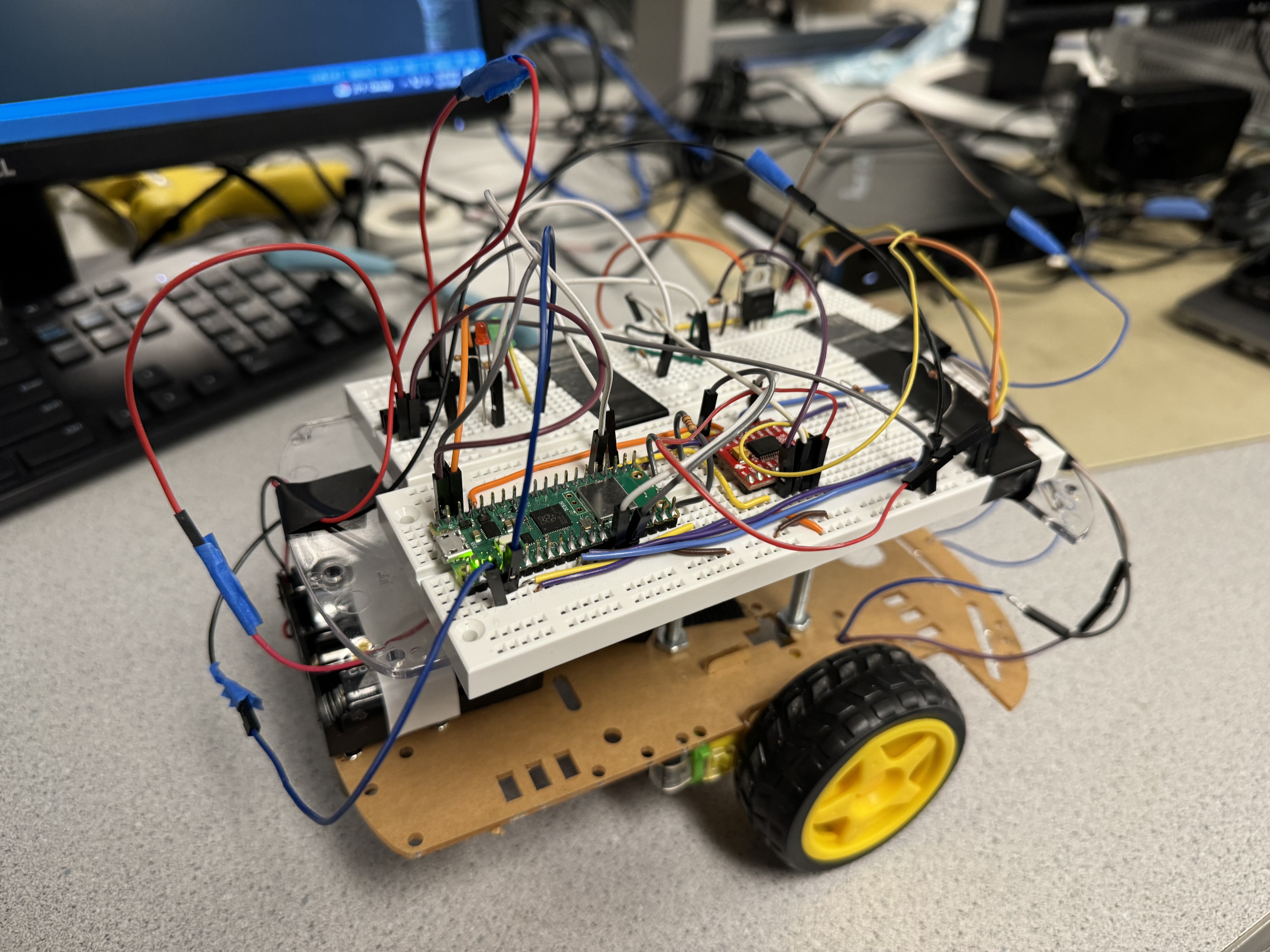
Figure 1 shows the connection implemented on the plastic sheet, where there are DC motors, electromagnet, motor controller, Pico W, etc. In the figure on the right, it can be seen that the two breadboards containing motor and electromagnet control circuits are installed on the top layer of the plastic board. Additionally, in the middle of the figure, we can observe that the electromagnet is installed in front of the robot, which enhances the convenience to grab the metal on the ground, and in the right, it can be observed that the two DC motors are assembled on the bottom of the car, driving those two wheels.

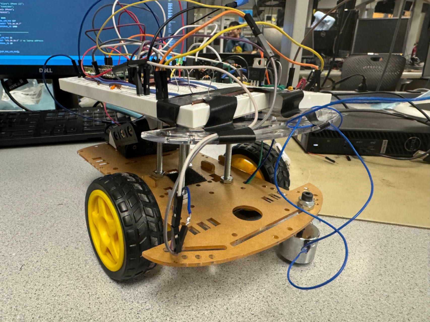
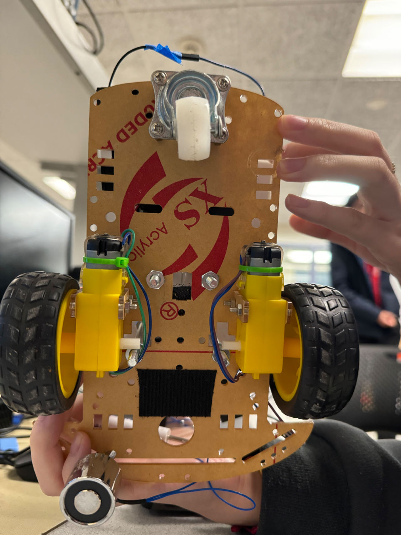
Figure 1. Mechanical Connection of the Robot
Figure 2 displays the overall hardware connection of our final project, Remote-controlled robot with electromagnet implemented on RP2040. The microcontroller used is the Pico W, as it has the Wi-Fi connection module, which is required in the remote control part of our project. And we use two sets of batteries to power the device, one is 4.5V to power the Pico W by connecting to VSYS and GND pins, and the other is 6V to power the motor and the electromagnet. In the following sections, detailed hardware design will be fully illustrated, including motor and electromagnet control circuits.
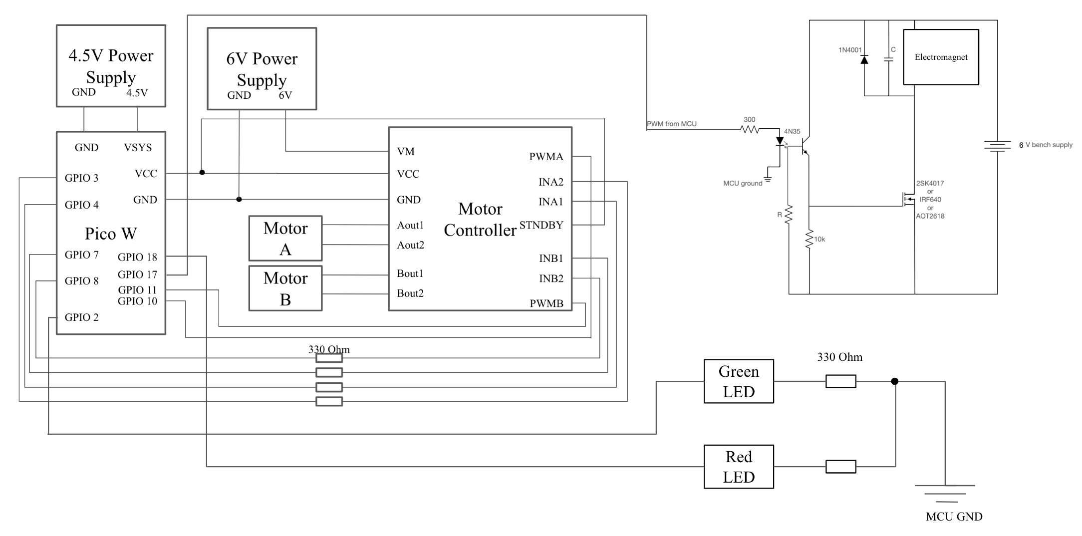
Figure 2. Hardware Connection of the Robot
ii. Motor Control Circuit
We applied the motor control chip as the H bridget to control the wheel to move forward and backward. In this project, Sparkfun TB6612FNG dual-channel motor controller is chosen as the motor control module, and the pinout diagram is listed in Figure 3. According to the hookup guide [1], the motor controller can be connected to the Pico W to realize certain functions, which is shown in Figure 2. VM is connected to the 6V power supply, used for powering the motors; VCC is connected to the 3.3 Volts output from the Pico W for powering the controller. STNDBY basically acted as a chip select pin, so it was also connected to the 3.3 Volts output from the Pico W to maintain the control of the motors. In addition, for the motor A, we select available pins, GPIO 3 and GPIO 4 for INA1 and INA2 respectively, and then GPIO 10 for PWMA, continuing the previous LED setting. The Aout1 and Aout2 outputs are connected from the motor controller to the DC motor. As for the motor B, we select GPIO 7 and GPIO 8 for INB1 and INB2 respectively, and GPIO 11 for PWMB. The mechanical design of the motor ciucuit in shown in Figure 4 on the bottom breadboard.
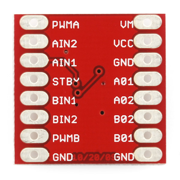
Figure 3. TB6612FNG Motor Controller Pinout Diagram
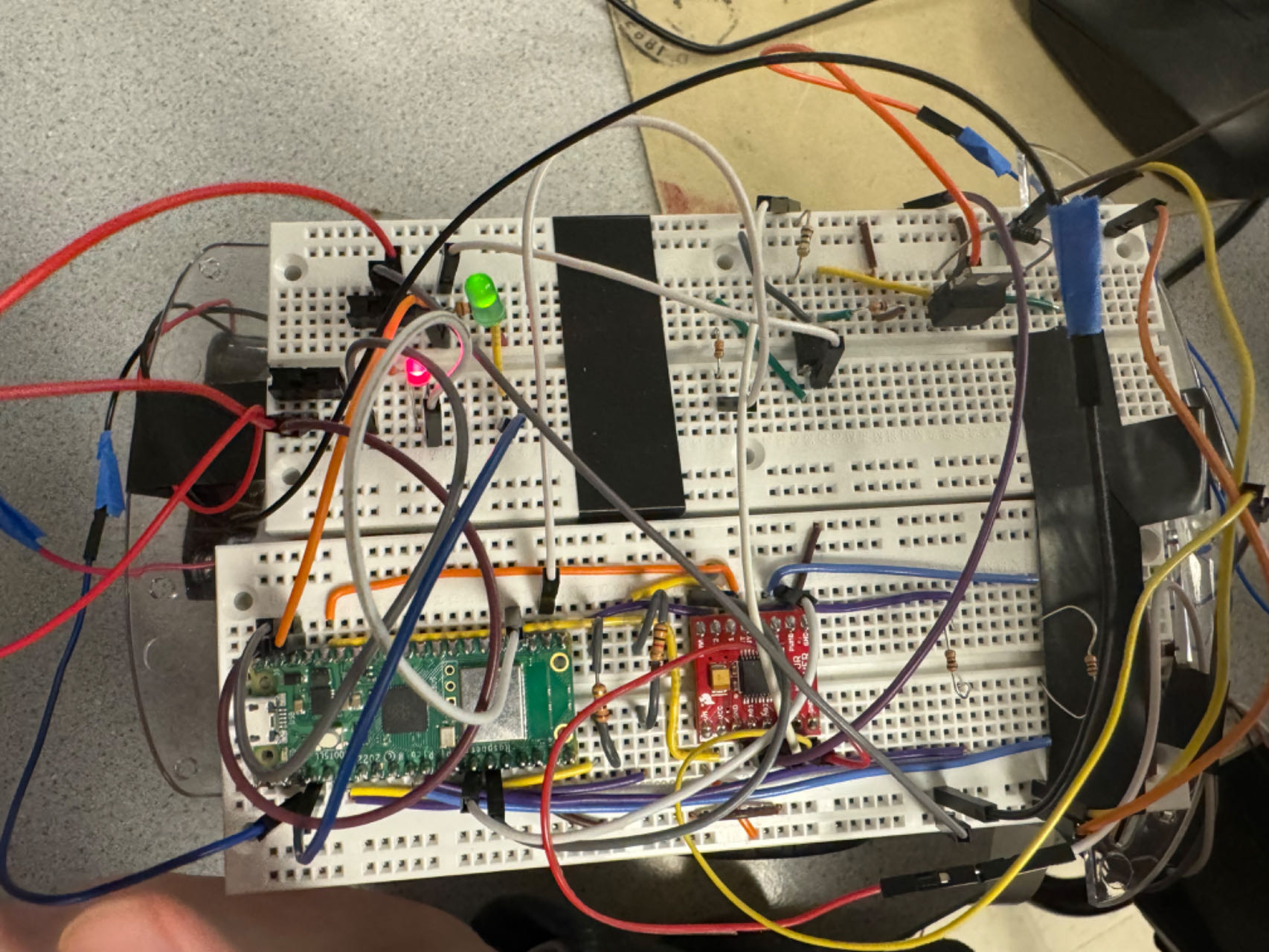
Figure 4. Circuits Construction
iii. Electromagnet control circuit
Since the circuit shown in Figure 5 could drive the motor in Lab 3, it might be able to drive electromagnet as well, so we tried this circuit and it performed perfectly. Consequently, the circuit was implemented by only changing the motor into an electromagnet. When the input signal on the left is set to high, indicating 3.3V from the microcontroller, the transistor inside 4N35 module the MOSFET IRF640 can be forward biased, and then the electromagnet can be turned on.
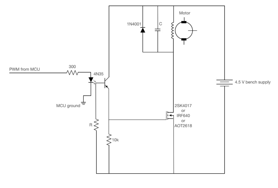
Figure 5. Electromagnet Drive Circuit
Program Design
i. Program Overview
- Motor control
Several motor control functions were defined, including Stop(), Forward(), Reverse(), TurnLeft(), TurnRight(), ReverseTurnleft(), and ReverseTurnRight(), which can be applied in the PWM interrupt service routine to control the moving direction of the remote-control robot. On the basis of Lab 3 assignment, there was only one PWM GPIO set, so in this project, we needed to initialize another PWM GPIO, according to the Pico W datasheet. Additionally, in the PWM ISR, we defined 7 states to correspond to each moving direction, where the state would be switched based on the UDP packets received from the Wi-Fi wireless connection channel. In this case, GPIO 10 and 11 were set as the PWM channel of the motors according to Figure 6, and GPIO 3, 4, 7, 8 were chosen to move the motors forward or backward.
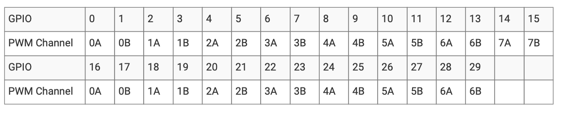
Figure 6. Mapping of PWM channels to GPIO pins on RP2040 [2]
- Electromagnet control
Since the motor control circuit from Lab 3 has been applied in this module, we only need to set the input signal high, coming from GPIO 17, to turn on the MOSFET IRF640, and later turn on the Electromagnet. Furthermore, we implemented a red LED to indicate the status of the magnet, controlled by programming GPIO 18.
- Wi-Fi module
Concerning Wi-Fi connection, we consulted with the UDP packet sending program from Prof. Land. Later, we combined the code with the official Wi-Fi connection code shown in the Pico W datasheet. Since it was hard to register the device on the RedRover, we tried to open a hotspot on our mobile phones as the Wi-Fi connection station. However, at first, the Pico W could not be connected to the hotspot, so we applied the Wi-Fi scan program from the Raspberry Pi Company to check the Wi-Fi around us until the name we wanted appeared. Therefore, we could successfully connect to our mobile phone.
Initially, we sent the characters through the software, UDP Sender/Receiver, to control the internal LED of the microcontroller to see whether it was successful. Furthermore, with the successful implementation of toggling the LED, the Python program would be run on the laptop to establish a UDP socket to send data, and we modified the code to send characters without pressing the ENTER key on the laptop keyboard.
ii. Program Organization
- Program on Pico W
Thread 1: protothread_udp_recv
Thread 1 is used to receive UDP packets containing the wheels and electromagnet control instructions, which is set as 'w' (forward), 'a' (left), 'd' (right), 's' (backward), 'c' (stop), 'k' (electromagnet on), 'l' (electromagnet off). The parameter of LAST_STATE will record previous state, and when the previous state is Forward or TurnLeft and receiving 'd', the motor will be set to STATE = 4, representing TurnRight(), while when the previous state is Reverse or ReverseTurnLeft and receiving 'd', the motor will be set to STATE = 6, representing ReverseTureRight(), and under other similar condition, it will be programed to similar actions, since it ensure that the robot can turn left or right backward when it is generally moving backward. Furthermore, the current state parameter is controlled by STATE and set under all the conditions mentioned above. As for electromagnet control, gpio_put(ELECTRO_CONTROL, 1) function is implemented to turn on the magnet and gpio_put(ELECTRO_CONTROL, 0) is used to turn it off. Additionally, a red LED is applied to demonstrate the current status of the electromagnet, showing it is on or off. At first, this thread only received numbers for testing, represented by LED toggling, which will be fully illustrated in Thread 3 section. Later, it was modified to receive characters by the Python script on the laptop.
Thread 2: protothread_serial
This thread is implemented for testing and debugging, which is a significant proportion of this project, and without which the efficiency cannot be ensured. It is basically modified according to Prof. Adams's demo code. When we were in the starting phase of motor control implementation, the serial interface should be used to debug and test the movement of the wheel.
Moreover, the actions and control number is shown in the PuTTY window by the function:
sprintf(pt_serial_out_buffer, "0 duty cycle, 1 forward motor, 2 reverse motor, 3 turn left, 4 turn right, 5 turn on electro, 6 turn off: ");
Therefore, users are able to debug the code after uploading the program into Pico W. Thereafter, when the motor and electromagnet can perform well, this thread can alsso be commented out to simplify the program.
Thread 3: protothread_toggle_cyw43
This thread is used for testing as well, and it can be commented out as long as the UDP packets can be successfully sent between the Pico W and the laptop. Initially, it is shown in Figure 7 that the Microsoft packet logger named UDP Sender/Receiver is opened on the laptop to send UDP data to the Pico W, by setting up the IP address and port number, and the Pico W can receive data by implementing Thread 1. To prove that the Pico W has received the message, the function protothread_toggle_cyw43() is implemented to test the result. Therefore, when the number of '100' is received by the Pico W, the blinking frequency of the internal LED would be changed, and with the increase of the sending number, the frequency would be increased. Therefore, with Thread 3, the Wi-Fi connection can be perfectly verified and all the following processes can be made after this.
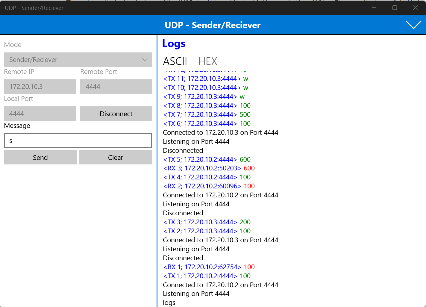
Figure 7. UDP - Sender/Receiver
PWM ISR
First, all the 7 motor movements are defined as individual functions, which will be easy to call later in the PWM ISR. For instance, the Forward() function is shown below, and others with the similar structure:
void Forward(int speed) {
gpio_put(MOTOR1_SELECT1, 0);
gpio_put(MOTOR1_SELECT2, 1);
gpio_put(MOTOR2_SELECT1, 0);
gpio_put(MOTOR2_SELECT2, 1);
control = speed;
control1 = speed;
}
Inside the PWM ISR, we separate the conditions by detecting the value of STATE. If STATE is equal to 0, it is the initialized stage, which is Stop state, and if STATE is equal to 1, it will set the motors to Forward state. All the control conditions are fully listed in Figure 8. With the actions determined, the PWM signal value will be sent to the corresponding GPIO by the following code, where we only apply one slice_num with two channels, PWM_CHAN_A & PWM_CHAN_B:
pwm_set_chan_level(slice_num, PWM_CHAN_A, control);
pwm_set_chan_level(slice_num, PWM_CHAN_B, control1);

Figure 8. PWM Control State
Main program
In the main program, we first need to set up the Wi-Fi connection between the Pico W and the laptop. If the Wi-Fi connection is achieved, a green LED will be turned on to indicate this status. After the connection, the UDP packet sending process will be initialized and all the GPIO and PWM ISR will be established. Furthermore, we can complete the main program by adding all the threads we want.
- Program on Laptop
sending.py
With the successful implementation of toggling the internal LED through Wi-Fi connection, the Python script was created on the laptop to automatically connect to the IP address of the Pico W. Instead of pressing the ENTER key on the laptop, an easier way should be implemented to send control instructions through the wireless channel. Hence, the function getch.getch() can be applied to ensure not waiting for pressing ENTER key. After this modification, a Python port can be opened in the VSCode terminal by setting up the corresponding IP address and port number, so we can directly type the command characters into the terminal window without pressing ENTER key, which enhance the real-time control capabilities of the robot.
Results and Analysis
Results
The project was overall a success; the system could respond quickly when instructions were sent from the laptop and it was also user-friendly with a simple interface. As shown in the demo video, the main functionality of the remote control robot was well realized, with a delay which was approximately less than half second. During the demo, when 'w' was pressed on the laptop keyboard, the robot was able to move forward, when 's' was pressed, it could move backward, and etc. Furthermore, characters 'k' or 'l' could be used to turn on or off the electromagnet. However, only the open-loop control algorithm had been applied on the current digital system, and since the PID control algorithm had not been implemented, the two wheels might have different angular speeds, which would cause inaccuracy in motor control and need to be adjusted manually.
Analysis
- Error 1: Wrong connection with motor control chip
At first, the motors were not working after connecting the motor control module with the Pico W. Later, it was found that the wire connecting STNDBY pin and the VCC pin of the microcontroller was not linked acting like the function of chip selection, which led to the failure in motor control.
- Error 2: PWM control
After adding another PWM signal GPIO, the two could not function properly at the same time. Later, it was discovered that the GPIO number should be carefully chosen before the PWM ISR establishment. As it was shown in Figure 8 in the PWM ISR section, if we wanted to use one slice_num with two channels, we should choose the GPIO number based on the table listed in the RP2040 datasheet. Therefore, with this modification, we could successfully set up the PWM control of the motors.
- Error 3: Wi-Fi connection
When configuring the Wi-Fi connection between the Pico W and the laptop, our initial attempt to connect them via the common Wi-Fi network 'RedRover' was unsuccessful. We discovered that connecting to 'RedRover' required a complex registration process. After seeking advice from teaching assistants and professors, we opted to simplify the process by creating a hotspot, ensuring a direct Wi-Fi connection between our laptop and the Pico W. Furthermore, we applied the Wi-Fi scan code from the official Github resources to check the status of all the networks in the nearby regions, and then we were able to connect the device to the network.
- Error 4: Mistake in electromagnet connection
As we neared the completion of our project, we scheduled a comprehensive re-evaluation of all functionalities following a brief pause. Unexpectedly, we encountered an issue where the electromagnet showed no magnetic response despite the system being powered on and receiving the PWM signal triggered by the keyboard. Initially, we tested the electromagnet directly with a power generator, but to no avail. Subsequently, we checked the PWM signal from the Pico W using a signal generator, which appeared to be functioning correctly.
Concerned about potential defects in the electromagnet, we reordered two additional units as replacements. However, upon a detailed inspection the next day, we discovered that the issue was caused by an incorrect connection: one terminal of the electromagnet was connected to the negative pole of the power, which was supposed to connect to the positive pole and this mistake prevented the electromagnet from operating. After rectification, the robot could perform perfectly.
Conclusions
It can be concluded that this project of a remote control robot was overall a success, although there were many challenges encountered. Upon analyzing our design, we find that the results closely align with our expectations, demonstrating the system's robustness and effectiveness. Reflecting on the process, we would consider implementing a PID control algorithm in future iterations to enhance precision and reduce the response time. Moreover, it can be considered to implement the automatic design of this device without any manual adjustment. For instance, the robot can be programmed to automatically search for the metal in the vicinity and turn on the electromagnet to grab the objects. As it is inspired from remote-controlled space robot, other functions can also be added into this project in the future, including connecting through other wireless channels, installing robotic arms for picking up objects, powering by solar battery, etc, which can benefit remote control tasks or even space operations.
Besides, our design adhered to applicable standards by incorporating proven methodologies and by referencing established intellectual property with appropriate usage. For the intellectual property consideration, we referenced the programs of Prof. Adams and Prof. Land, for configuring PWM GPIO, Wi-Fi connection and serial interface. For example, we built out electromagnet control circuits based on the motor control circuit we had learnt from Prof. Adams in Lab 3: PID control of a 1D helicopter, and we reconstructed the Wi-Fi control program based on Prof. Land's UDP receiving program and the official configuration example from Raspberry Pi company [3]. Additionally, our project did not involve reverse-engineering any existing design. Instead, we developed our system based on fundamental principles and concepts taught in the course, ensuring originality in our approach.
Team Members

Wenyi Fu
wf223@cornell.edu
Design Motor Control Circuit and Program
Design Electromagnet Control Circuit and Program
Wi-Fi Configuration
Design Python Program on Laptop Opening UDP Socket
Debugging and Testing
Report and HTML File Writing

Klora Wang
hw768@cornell.edu
Wi-Fi Configuration and Testing
Debugging and Testing
Report and HTML File Writing
References
Wi-Fi scan program
Wi-Fi connection
Electromagnet control circuit
PWM configuration and serial interface
Appendix A: Notices
"The group approves this report for inclusion on the course website."
"The group approves the video for inclusion on the course YouTube channel."
Appendix B: Parts List
- Raspberry Pi Pico W - $6.00 - Provided in lab
- SparkFun Motor Driver - Dual TB6612FNG (1A) - $13.5
- 5V Electromagnet - 5 Kg Holding Force - P25/20 - $9.95
- Robot Kit - $19.95
- LEDs, MOSFETs, Resistors and Wires, etc. - Provided in lab
Total: $49.4
Appendix C: Code
The code is shown in the repository: ECE5730_Remote_Contrlled_Robot_with_Electromagnet