Radiochat
Communicate over radio frequencies using your phone!

Introduction
Radiochat is a device that pairs to any other device with a browser over WiFi, and can be used to transmit and receive LoRa messages. This has a number of practical applications, notably, the Radiochat device can be paired to mobile phones, and messages can be exchanged using the devices in locations without WiFi or cellular networks.
My inspiration to build Radiochat came from a practical experience. I am a member of the Cornell Rocketry Team, and our team travels to remote locations in New Mexico to launch our rockets. These locations often do not have cellular service or WiFi, and we need an effective way to communicate. In the past, we have used handheld radios, but communicating precise numbers over handheld radios can be difficult. Packet radio provides an effective way to handle this communication.

Packet Radio & LoRa
Radio, in the way that most people think of it, involved transmitting sounds over the air. Usually, this is done by modulating the frequency (FM actually stands for "frequency modulation") or modulating the amplitude (AM stands for "amplitude modulation") of the sine wave.
This works really well for analog signals, like sounds, but works less well for digital signals. There are a number of modulation schemes for digital signals, morse code (or CW, as it is called in the amateur radio community) being one of the oldest and most famous!
One of these modulation schemes is LoRa (which is actually short for Long Range). LoRa is a proprietary (Patent US9647718B2) modulation scheme developed by Semtech. LoRa uses spread-spectrum techniques (meaning that the signal is broadcast over multiple frequencies) to broadcast data over radio waves. It's commonly used in IoT devices, especially those in remote locations because LoRa waves can travel over large distances.
I used the RadioLib library to perform the LoRa broadcasts, and the RFM96W module, which includes the hardware necessary for LoRa modulation. RadioLib is written for Arduino, so getting it to work on the Pico required some additional work. RadioLib has support for hardware abstraction, so I wrote a RadioLib Hardware Abstraction Layer for the Raspberry Pi Pico. This allowed RadioLib to work with the Pico's GPIO devices, including its SPI buses, its interrupts, and its timers. This HAL is implemented in the PicoHAL.hpp file in the source code.
TCP/IP
Unfortunately, the internet as a technology is quite complicated. When talking about the internet, we often discuss the Internet Protocol Suite (sometimes referred to as TCP/IP, two of the protocols in the suite, the Transmission Control Protocol and the Internet Protocol). TCP/IP is split into four different layers:
- The Link Layer defines how computers physically connect to other computers. It defines protocols like Ethernet (RFC 894 and IEEE 802.3). The main document that defines the Link layer is RFC 1122. It is the lowest layer on the internet stack. To use the post office as an analogy, the link layer is the trucks, boats, and planes that transport the mail around the world.
- The Internet Layer sits on top of the Link Layer. It's also defined in RFC 1122. It defines how the simplest packets are sent between computers, or "hosts." It doesn't explain what these packets contain or when they're sent, just how to transport them to get to their intended destination. It defines protocols like IP (as in IP address, RFC 791). The internet layer is just about getting packets from one host to another. It doesn't make sure that the packet wasn't corrupted, or that several packets were received in order, or even that no packets were dropped.
- The Transport Layer sits on top of the Internet Layer. It defines protocols like TCP (RFC 9293) and UDP (RFC 768). These protocols handle the things that the internet layer doesn't handle: packet reordering, fixing corruption, sending acknowledgments, and more.
- Finally, the Application Layer handles many of the actual messages being sent. It defines protocols like HTTP (RFC 9110, RFC 9111 and others), FTP (RFC RFC 959), and even SMTP (used for sending emails, RFC 821). HTTP is very commonly used for communication over the web.
Each of these protocols are developed on paper. It's up to the developer of each system to implement them. Many protocols are already implement in the Pico SDK's standard library, and in the Lightweight IP library; however, there are a few that you must implement, mostly in the application layer.
Here's an example of a DNS request TCP/IP packet, which I'll go more into later.
0000   08 00 00 00 00 00 00 01 03 04 00 06 00 00 00 00   ................
0010   00 00 00 00 45 00 00 50 59 09 00 00 40 11 23 5e   ....E..PY...@.#^
0020   7f 00 00 01 7f 00 00 35 a1 96 00 35 00 3c fe 83   .......5...5.<..
0030   cd dc 01 20 00 01 00 00 00 00 00 01 07 65 78 61   ... .........exa
0040   6d 70 6c 65 03 63 6f 6d 00 00 01 00 01 00 00 29   mple.com.......)
0050   04 d0 00 00 00 00 00 0c 00 0a 00 08 31 fc 8e 8c   ............1...
0060   e7 4a 66 f3                                       .Jf.
This is a hex dump. On the left, we see each byte of the response, represented in
hexadecimal. On the right, we see the ASCII character represented by each byte, if it is
printable. Otherwise, it is a . character.
I've colored each of the different protocols being used in the response in a different color.
- Link Layer - Linux Cooked Capture v2 is in blue. I captured outgoing packet locally on my computer, before it was sent to the network card, where it would be replaced by an Ethernet packet. It specifies the destination hardware address for the packet, and my computer's hardware address (I zeroed both out for privacy). I would be sending the packet to another computer that my machine is physically connected to, likely the router. The router would then replace this part of the packet with the next machine that it is sending this packet to, likely a modem.
-
Internet Layer - Internet
Protocol v4 is in red. It includes my IP address, 127.0.0.1
(
7f 00 00 01) (because this packet was captured locally), and the IP address that the packet is going to, 127.0.0.35 (7f 00 00 35). -
Transport Layer - User Datagram
Protocol is in green. It includes the source port (41366,
a1 96), and the destination port (53,00 35). It also includes the message length (60,00 3c), and a checksum to make sure that the message is intact (fe 83). - Application Layer - Domain Name System Query is in yellow. I'll go through how the Domain Name System works later on.
DHCP
The Dynamic Host Configuration Protocol (DHCP, RFC 2131) is an application-layer protocol used to assign IP addresses to hosts. The Pico W SDK has the necessary code to serve as a wireless access point (meaning that it can broadcast it's own network), but a DHCP server needs to be implemented so that hosts can connect to the network.
                                sequenceDiagram
                                    Client->>+Server: Discover: DHCPDISCOVER
                                    Server->>+Client: Offer: DHCPOFFER
                                    Client->>+Server: Request: DHCPREQUEST
                                    Server->>+Client: Acknowledge: DHCPACK
It takes four steps to get a DHCP address, as shown in the diagram above. Each of these messages is transmitted over UDP.
-
First, the client, which doesn't know the DHCP server's IP address, broadcasts a
DHCPDISCOVERmessage to the IP address255.255.255.255. This message includes the hardware (MAC) address of the client making the request (fieldCHADDR, for client hardware address), and a magic cookie, the value0x63825363, which identifies the message as a DHCP request. -
Next, the server responds with a
DHCPOFFERmessage. It includes two more fields,YIADDR, your IP address, the new IP address being offered to the client, andSIADDR, server IP address, the IP address of the DHCP server. It also includes theCHADDR, so the client knows that the packet is intended for it. It also includes the magic cookie. -
Now the client knows an IP address that is available! It needs to request that IP
address to claim it. It uses a
DHCPREQUESTmessage to do so. This DHCP message just includesSIADDR,CHADDR, and a special field, DHCP option 50, which specifies the IP address being requested, the one that was received in theYIADDRfield of theDHCPOFFERmessage. It also includes the magic cookie. -
Finally, the DHCP server needs to acknowledge the request! It sends back a
DHCPACKmessage to do so. It incluesSIADDR,CHADDR,YIADDR, and DHCP option 51, which specifies the amount of time that the client can lease the IP address for. After the lease expires, the client must request a new IP address using DHCP.
I ended up using the DHCP library from the Micro Python project (MIT licensed), but spending time understanding how DHCP works helped me a lot in debugging the network aspects of the project.
DNS
One of the other parts of the TCP/IP stack that you need to implement to host a network from
the Pico W is a DNS server. DNS is the Domain Name System, used to map
domain names, such as example.com, to IP addresses, such as
93.184.216.34. The dig command can be used to make a DNS request,
which becomes useful in testing.
Normally, DNS works by making recursive queries to other DNS servers, until some DNS server finds the IP address associated with a domain name; however, for my use case, this wasn't necessary, as every domain needed to resolve to the same host: the Pico W. Therefore, we only need the front-end of the DNS server—we don't actually need to look up IP addresses to respond with.
To better understand DNS, I thought that it would be a good idea to simply look at a DNS
request. To get the DNS request, I used tcpdump to get the DNS traffic for my
computer for one request generated by DiG: dig example.com.
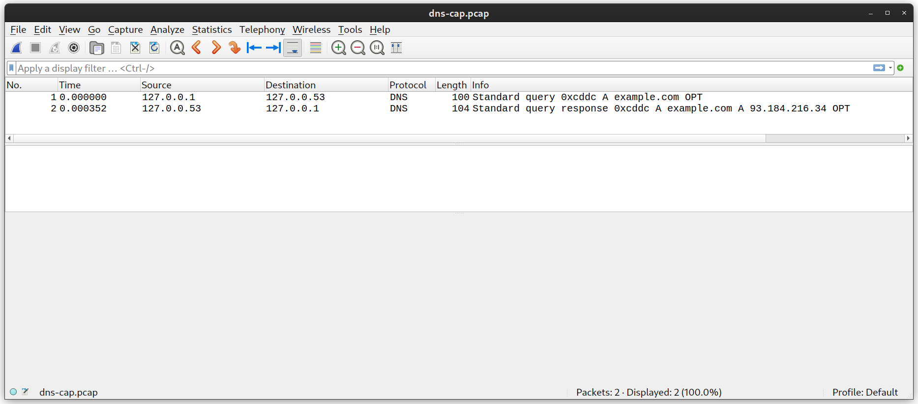
As you can see, there are two packets, one outgoing, and one incoming. Let's take a closer look at the outgoing packet (it's the same packet that we looked at earlier), but this time, let's only look at the DNS section. (I also ran out of distinguishable colors, so this time, I'm going to mark it up with a pen)

The response follows a very similar format, except it contains an answer rather than a question! The answer simply contains the IP address of the host, and some additional information.
I also ended up using a library for DNS requests. It was provided in one of the pico-examples, which are licensed under the BSD-3-Clause license.
HTTP
The last internet suite protocol that I had to implement was the Hypertext Transfer Protocol, or HTTP. HTTP is used to send files over the internet. Most commonly, it's used for websites.
I actually knew a lot about HTTP from older projects of mine. In fact, I once ran a CTF/programming competiton, and one of the problems that I wrote involved handwriting HTTP requests.
One of the best things about HTTP requests is how simple they are. HTTP only uses ASCII printable characters. Let's take a look at an HTTP request.
GET /index.html HTTP/1.1
Host: example.com
As you can see, the request is incredibly simple. This is a GET request, used
just to get data. GET requests are not allowed to change the state of the
server. The path to the file that we're getting is /index.html, and we're using
HTTP version 1.1. The host that we're requesting from is example.com.
The information that follows the first line of the request are headers. Each header has a
name, starting with a capital letter, and a value. The name and value are separated by a
colon and a space. Host is not the only header in most requests; however, it is
the only header that you need to send a GET request.
Now, let's look at the response.
HTTP/1.1 200 OK
Accept-Ranges: bytes
Age: 549055
Cache-Control: max-age=604800
Content-Type: text/html; charset=UTF-8
Date: Mon, 18 Dec 2023 01:36:08 GMT
Etag: "3147526947+gzip"
Expires: Mon, 25 Dec 2023 01:36:08 GMT
Last-Modified: Thu, 17 Oct 2019 07:18:26 GMT
Server: ECS (nyb/1D10)
Vary: Accept-Encoding
X-Cache: HIT
Content-Length: 1256

<!doctype html>
...
As you can see, the response follows a similar format to the request. Again, there are only
a few important parts. HTTP/1.1 is the version of HTTP that we're using, and
200 OK is the response code. There are many response codes to choose
from, each conveying a different meaning. The only required headers are
Content-Type, which conveys to the client the MIME type of
the content being sent back, and Content-Length, which contains the length of
the data being sent back.
When implementing the HTTP code, I started with the HTTP server found in pico-examples. Unfortunately, that server only supported GET requests. GET requests are only meant to fetch information, and not change the state of the server, and there's good reason for this! Many browsers issue GET requests for other links on a page, even if you don't click them. That way, these pages seem to load faster when you do click them (a technique called prefetching).
If you change state or perform actions on a GET request, you may inadvertently perform these actions during a prefetch request. There is a classic story of someone who connected their garage door opener to an HTTP server, and used GET requests to open and close it. The person also bookmarked the page to open and close it, and their browser prefetched their bookmarks on a new tab. Each time they opened a new tab, their garage door opened or closed! I didn't want LoRa messages to be sent inadvertently, so, I also needed to implement another request type on the server, POST requests.
POST requests are often used to update data, in fact, HTML <form>
elements can automatically issue POST requests when they're submitted, so I didn't need to
implement any JavaScript.
Implementing POST requests was somewhat similar to how the server implemented GET requests,
but there was a little extra complexity due to having to account for request bodies,
contained in POST requests but not in GET requests. Due to space constraints on the
microcontroller, I only support POST requests up to 2048 bytes in size,
including headers. This is a bit unfortunate, but a limitation due to the space available on
the RP2040.
Software Design
The software design for this project was relatively simple. I split the work into two parts: the web server and the radio. Each was done on a different core. There were two shared resources between the cores, a buffer that had the last message that the radio received, and a buffer that had the next message to transmit (if there is one).
The Radio would attempt to listen for a message for 500 ms. If it heard the beginning of a LoRa packet, it would continue listening, otherwise, it would stop listening, and check to see if there was a message to transmit. If there is a message to transmit, it would transmit the message. Otherwise, it would return to listening.
I first tried to use the hardware spinlocks on the RP2040 to ensure that only one thread
could access each buffer at a time, but I couldn't get them to work correctly. I ended up
simply using a one-bit flag and and the volitale keyword to determine if a new
message was ready to transmit. I did not end up fixing the race condition on the receive
buffer, but I was never able to replicate that error. If the error did occur in practice, it
could be fixed immediately by the end-user reloading the page.
Hardware
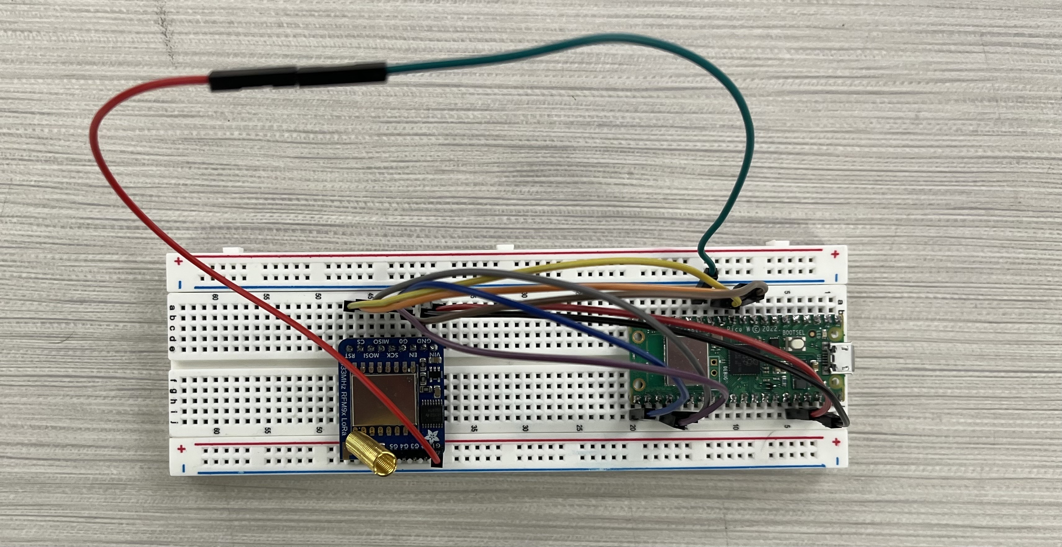
Hardware design for this project was also very simple. The radio module was connected over SPI to the Pico W, and communicated over SPI, with two interrupt pins.
One of the first issues that I ran into was that I was unable to communicate with the radio. I used a logic analyzer to attempt to debug the SPI lines, but my SPI packets matched the datasheet, and I was getting what seemed to be random values back. Finally, I noticed that the reset pin on the radio module was active high instead of active low, so I was holding the radio in reset. Pulling the reset pin high fixed the issue.
Conclusions
Overall, the design worked very well! I am happy with the results. If I had more time, I would like to implement websocket communication, so you don't need to reload the page to receive data from the page. Additionally, I would like to make the web interface nicer, which would likely require more space on the Pico. This could be solved by attaching external flash memory, and using that to store extra data.
There is also a bug with Darwin-based operating systems sending messages. I believe that it is a line-termination problem, as Darwin operating systems send LF at the end of an HTTP request, while most other operating systems (including Linux) send CRLF. I hope to test this more in the future, but unfortunately, I do not have a Mac that I can use to test it available. An alternative would be switching to Bluetooth based communication, and developing a mobile companion app.
I learned a lot from this project, even though I used some external libraries and starter code. It has been really interesting to implement such a complex system when you're so resource constrained. As some next steps, I hope to print a PCB, clean up the code, and fix the few bugs that I mentioned so that hopefully, I can use the system more effectively.
Appendices
Appendix A: Permissions
- The group approves this report for inclusion on the course website.
- The group approves the video for inclusion on the course youtube channel.
- The content of this webpage is licensed under the Creative Commons Attribution-NonCommercial-NoDerivatives 4.0 International Public License (CC-BY-NC-ND 4.0). Attribution is required in redistributions.
Appendix B: References
- Richard Sharpe, Ed Warnicke, Ulf Lamping. Wireshark User's Guide, Wireshark.
- HTTP, Mozilla Developer Network
- Media Types, Internet Assigned Numbers Authority
- Prefetching, Mozilla Developer Network
- RFC 1035: Domain names - implementation and specification, Internet Engineering Task Force
- RFC 1122: Requirements for Internet Hosts - Communication Layers, Internet Engineering Task Force
- RFC 2131: Dynamic Host Configuration Protocol, Internet Engineering Task Force
- RadioLib, Jan Gromeš
- Wireless communication method, Olivier Bernard André Seller