Pond Water Simulation
Matthew Hui and Tomas Choi
For our final project, we made a 2-d simulation of pond ripple behavior and simulated the natural response to skipping a rock across the water.
https://www.youtube.com/watch?v=uaxF074Uj-o
Video 1: Final Demo Video
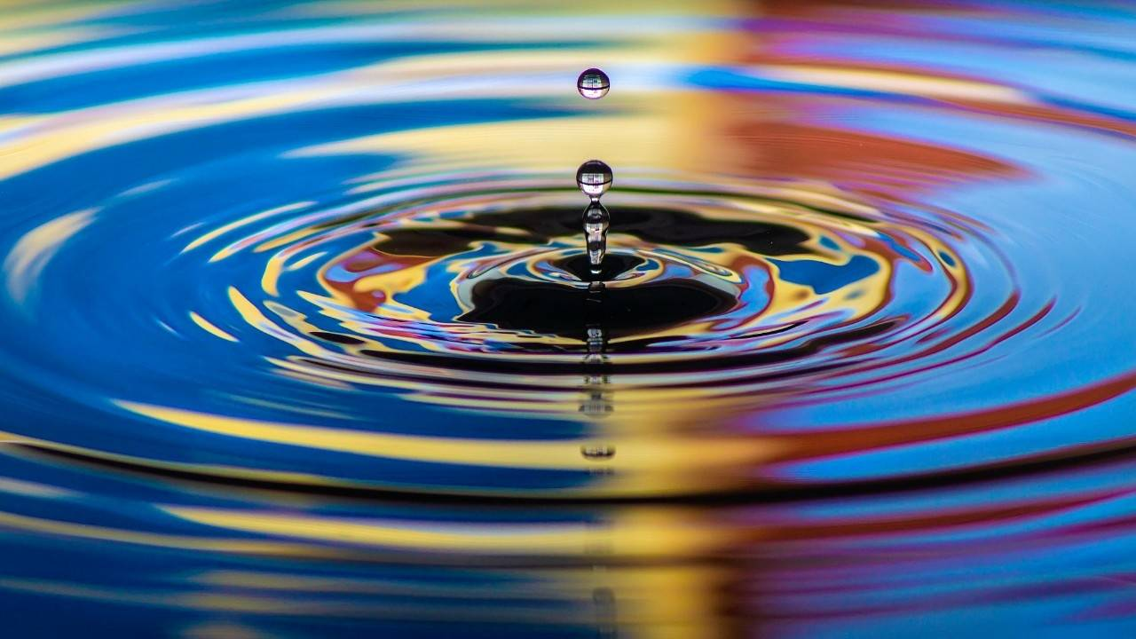
For our final project, we decided to create a simulation of a small pond and the resultant behavior observed when skipping rocks. When designing the overall scope of our lab, one of the natural phenomeyna we found interesting and wanted to replicate was the ripple wave effect that is seen when dropping an object in a still lake.
Source: https://savvy.directorprep.com/blog/the-ripple-effect
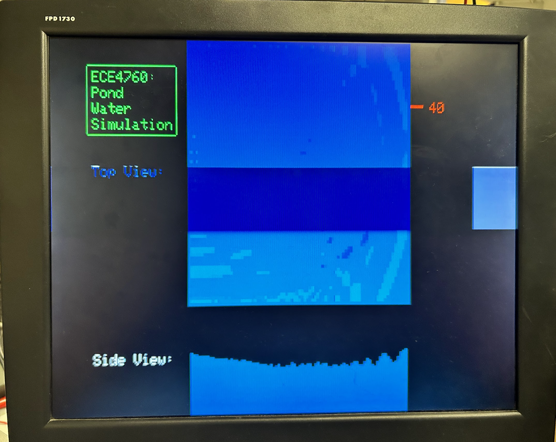
Thus, for the end-goal of our project, we wanted to create some sort of simulation where we had an organic behaving pond that would respond as naturally as possible to disturbances induced by dropping in rocks in different areas of our pond. We went through several design challenges and implementation methods and ultimately settled on trying to emulate the behavior with a 2 dimensional view of a pond. With a 2 dimensional view of the pond, we simulated the perceived heights of ripples and dropped rocks using different gradients of blue and also plotted the adaptive heights along a slice of our pond to provide further context on how the heights were changing. Below depicts the end product setup we had for our simulation.
Inspiration
After the boids lab, we were really impressed with the computer graphics capabilities that the Pico had and how visually accurate the motions looked. When looking for a project idea, we knew we wanted to do something related to computer graphics. From the boids lab, we also saw natural patterns emerge from randomly changing certain parameters of the boids, which really shocked us and inspired us to come up with some natural behavior that could be modeled in the VGA screen. Among the many possibilities we discussed, one of them was water simulation. We thought that the best way to demonstrate a simulation is natural is by the way it interacts with stimulus, which prompted us to incorporate stone skipping into our project.
Background Math
For the accurate simulation of the pond, we looked into many different equations, but we ultimately used the wave equation. More specifically, we used the discretized 2D wave equation derived by Hunter for the ECE 5760 Drum Synthesis lab. The 2D wave equation is described by
 ,
,
where 𝑐 is the speed of sound, 𝜂 is the viscosity coefficient, and 𝑢 is the height of the node directed out of the plane. The equation above is the continuous wave equation, but in the application of computer graphics, we are basically drawing each node every frame to make it look like a smooth transition of motion. Therefore, we used the discretized 2D wave equation derived by Hunter.

The way the discretized equation works is by calculating the next amplitude or “height” of the node based on its current amplitude, its past amplitude, and the amplitudes of the nodes around it. There are many constants in this equation, so for the purpose of our water simulation, we had to change these numbers to make our simulation the most visually realistic. We will discuss the implications of changing the different constants on our simulation in later sections, but the following is the final equation we used
 .
.
Logical Structure
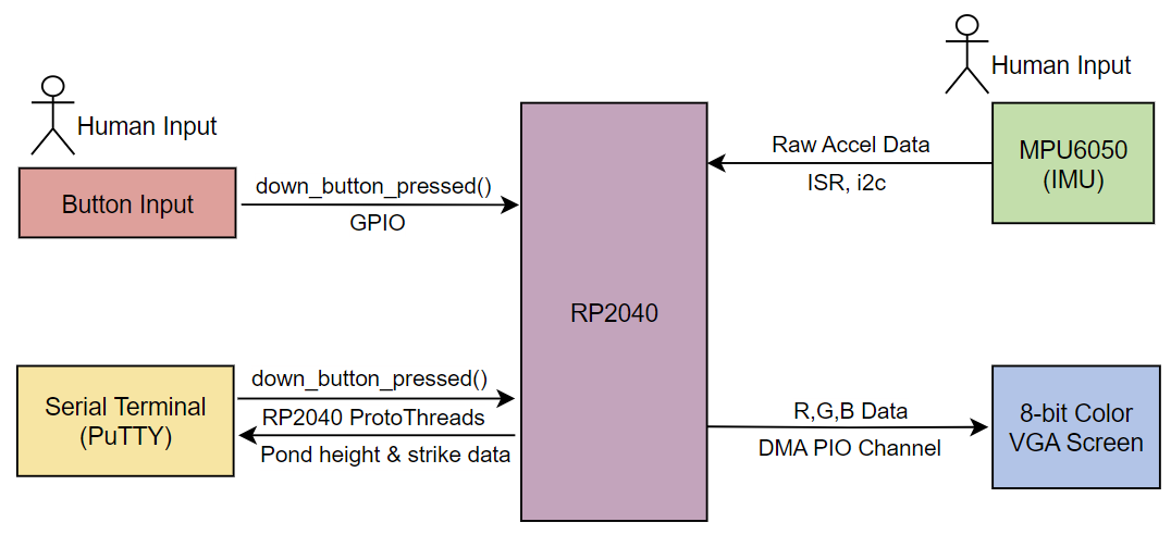
The structure of our project involves one single directory with 3 main files: the main program that is actually ran, a mpu6050 related file that includes all the helper functions needed to control the IMU, and a VGA graphics file that includes all the helper functions needed to set up all the colors, all of which interact as shown in Figure 1. The main program uses 3 threads: one to perform all the calculations related to the unstimulated water simulation, another to interact with the VGA screen and react to stone skipping, and another to interact with the serial interface. The details of the files and the threads will be discussed in the later sections of the page.
Figure 1: High Level Flowchart of Project
Hardware/Software Trade-Offs
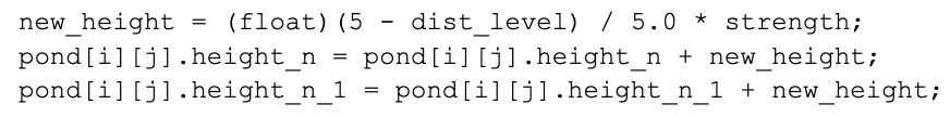
There was one significant hardware/software trade off due mainly to the memory limits of the RP2040. Our original vision of the simulation was to fill the entire VGA screen and have fish-like boids move around the water. However, after experimenting with our water simulation and the 8-bit VGA implementation, we realized that there was a limit to the amount of memory available. We kept encountering RAM issues, which we quickly narrowed down to the cause being the combination of the water simulation along with the 8-bit colors. Although we knew we could implement the fish simulation in the software, we also thought that the RAM problem was an obstacle we could not work around. Another problem we encountered was a decrease in resolution that led to one good area of the VGA screen to be unusable. If we tried to print or draw anything in the ⅕ of the right side of the VGA, we would encounter a weird issue, as shown in Figure 2. Therefore, we settled with the water simulation and only displayed it in the portion of the VGA screen that did not cause issues. We were not extremely disappointed because our main goal of the project was to do a water simulation, which was still possible. Looking back, one way we could have dealt with the extensive memory usage of the 8-bit VGA is by reducing it to something like a 5-bit VGA and simply using 1 bit for red, 1 bit for green, and 3 bits for blue. Since we only used blue to display the water particles, the color scheme that we get from these 5 bits might have been enough to create a believable water simulation.
Figure 2: Out of Bound Pixel Error
Patents/Copyrights/Trademarks
We did not directly copy any of the code we used, but we did modify existing code written by Hunter and Bruce related to the discretized 2D wave equation and the 8-bit VGA, both of which have Cornell copyrights. Other than those, we believe our project does not have any patents, copyrights, and trademarks issues.
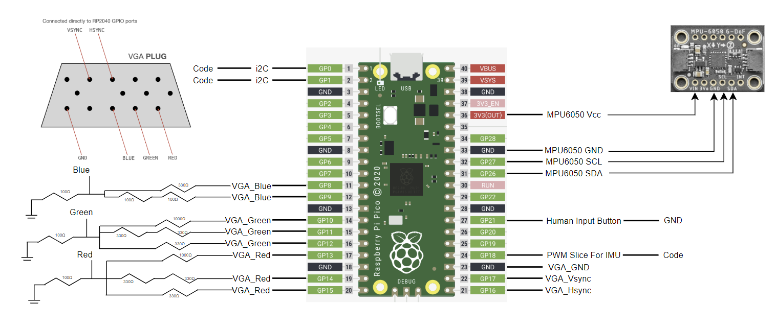
Figure 3: Hardware mapping of RP2040 used in the final project
Component Description
The hardware in our project included several modules and components that we had used in previous lab assignments in our class including: Pi Pico, 8-Bit VGA Driver, MPU6050 Accelerometer, and a simple GPIO button.
Pi Pico: The Pi Pico microcontroller utilized the RP2040 microcontroller chip which was the main engine driving our entire simulation on our chip. The chip has dual core functionality running at speeds of up to 133MHz, 30 GPIO ports that have a variety of functions related to each, support for i2c, UART, SPI communication protocols and 264 kB of SRAM available for use. To communicate with the Pi Pico, the RP2040 C SDK was utilized. The Pi Pico and its associated pins & ports are displayed above as the central figure.
8-Bit VGA Driver: The 8-bit VGA driver is functionally similar to the previous 3 bit VGA driver utilized in previous labs with the main difference being the amount of colors we can obtain on the VGA screen. Previously with 3 bits, we were only able to obtain 8 unique colors, however for our project since we were representing depth of water with a color gradient, we needed an array of a single color gradient. With the 8-bit VGA, we instead had 256 colors at our disposal, with gradients 8 different colors for a color. Since we are allocating more bits to our coloration, we had to compensate for it with the size of our overall screen, which decreased from 640x480 resolution to 320x240 resolution.
MPU6050 Accelerometer: The accelerometer used was the same from lab 3 since we decided to use the accelerometer component of the MPU6050 in order to determine and track hand swipes that simulated skipping stones.
GPIO Button: The button used was very simple as it represented a basic switch, setting a line to high or low depending on if the button had been pressed or not. The actual code logic for this feature was implemented by defining the associated GPIO pin in the code as described later on.
Setup
As depicted in the figure above, all of the components described were connected with their respective GPIO pins. The 8-bit VGA setup required additional resistor wiring compared to the 3-bit VGA since we had to add further definition to our voltage levels. In the lab, we were unable to acquire the exact resistance values that were described in the source example created by Bruce Land, and instead had to combine resistors in series to obtain values as close as possible. (For instance, in the case of GP11, it required 680Ω and in our setup we used 2 330Ω resistors in series, yielding us an effective resistance of 660Ω.) The MPU6050 accelerometer was attached to its required pins with extended male -> female pin connectors since we needed to add extra slack in our design in order to make the “skipping rock” component feasible.
To piece the hardware together, we took a modularized approach, adding in the new component whenever we were ready to add in the next feature. We started off with a very basic board, only containing the logic for the 3-bit VGA screen since our main concern was to determine whether or not our proposed equations and algorithm described below would work. Once we verified that we were able to obtain a working set of data, we then moved onto integrating the 8-bit VGA driver set up. This step took a while to create due to the complex nature of the appropriate resistor network set up and we spent extensive debugging time to ensure that our resistors were mapped and connected appropriately. With the visual features set up, we then integrated the MPU6050 into the project, using a similar approach to lab 3. (First ensuring that the connections were proper by testing it with a demo, then integrating it into our final project build.) The last thing that was added was our GPIO button which had a singular wiring on it.
Difficulties & Bugs Encountered:
Figure 3: VGA Color Bug
Figure 3 illustrates a common bug we encountered in our design where the displayed color was the wrong gradient from what we expected. It first prompted us to look into the rgb values we were encoding, however upon further analysis of our circuit and set up, we realized that we had swapped the connections between the red and blue pins on the VGA driver resulting in the orange color scheme seen above, which also looks very cool. .
Water Simulation
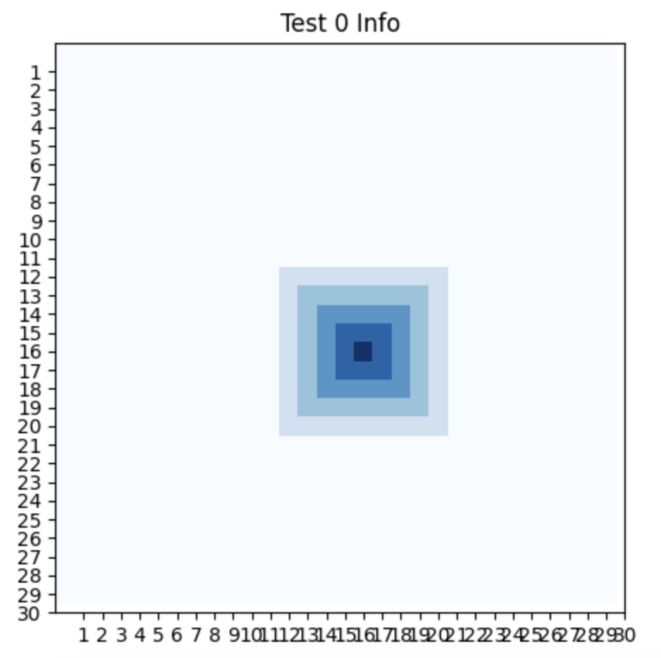
We based our implementation of the water simulation on the ECE5760 Drum Synthesis Lab, which also used the 2D discretized wave equation. Before trying to see how the water simulation looked, we focused on getting the wave equation implemented correctly. Therefore, we implemented it in Python and we were able to visualize and debug the simulation much more easily compared to when using the VGA. The way we did this was by storing all the data into arrays and then displaying the amplitudes with different colors picture by picture. With Python, we were not able to actually simulate the water, but we were able to determine two things: what were the maximum and minimum values that worked well with the simulation and what the wave equation actually looked like visually. Although we used the Putty interface to reference data throughout the lab, these initial measurements and visualizations gave us confidence that the wave equation looked promising.
Figure 4: Python Simulation of 2D Discretized Wave Equation
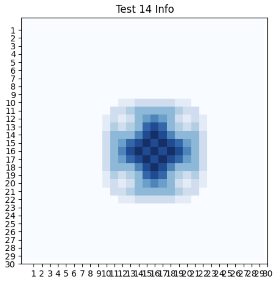
Therefore, we moved the water simulation implementation to a C program and initially used the 3-bit color VGA to display the water simulation. Although we were not able to accurately determine the depth of water due to the available color scheme, we did learn a couple of things. The first thing we learned was that while the water strikes looked good, the ripple effect was not as “satisfying”. It somehow felt that the strike was like at the top of the waterfall, but the ripple effect did not match the strength of that waterfall. Clearly, the way we debugged the water simulation portion of this project was not very “scientific”. Instead, we used very subjective measures that very often came from the answer to the following question: “Does it look convincing?”. We realized that the reason the striked looked that way was due to the way in which the ECE5760 Drum Synthesis Lab implements the strikes. It used an exponential function to map the heights of the nodes in a specific area to cause the ripple effect that came from the wave equation. In the context of drums, the exponential function made sense, but we realized that for the water simulation it was just not as convincing. Therefore, we took a more linear approach to induce the strikes. The strikes would be targeted to one specific node, and it would modify the height of every node in a radius of 5 from that node. Figure 5 contains the snippet of code to do this. The way it would modify each node was by taking the proportion of distance from the striking node, multiplying that to a specified strength, and then adding it to the height of the node.
Figure 5: Strike Implementation
Thus, the strike would take the form of a pyramid. Visually, it could be imagined as a hand pulling the one water particle up and thus also stretching and pulling the water particles around it, and then letting them go to cause ripples in the water. We observed that this implementation of the strike was more visually appealing and realistic.
Another thing we learned from translating our code to the VGA screen was that the ripples themselves would not stop for a long time and they would be too strong in areas where the striked should not have affected as much. Therefore, we recognized two problems: the unaffected nodes were interacting too closely with the nodes around them and the ripples would go on for a long time. The result of this was that the water simulation was more chaotic than natural.
Video 2: Chaotic Simulation
We dealt with this issue by tweaking the values of some of the constants in the discretized 2D wave equation. Our final equation looked like this:
.
The two constants that we modified in this equation were the ⅛ and the last 0.9999. In the Drum Synthesis lab code, the  was originally a
  . The reason we reduced this number was because we noticed that the heights of the nodes were being impacted too much by the heights of the nodes around them, and this was causing the nodes to continuously pass on the energy they had and be a factor in the chaos described previously. The last 0.9999 was originally a 0.9998. One might think that this does not greatly affect the simulation, but it does. The last term in the equation could be considered as the energy dissipation term that allows the water simulation to look realistic in terms of its amplitude change when the pond is unaffected over a substantial period of time. By reducing the constant of dissipation even a little bit, we were able to observe the simulation take the form of what we would actually expect to see from a pond. One of the reasons we were so strict on getting this initial water simulation right was because everything we had done up to this point was to create the unstimulated pond. When we say unsimulated, we refer to no stone skipping. Although it is in motion, one could call this the static state and were of the belief that our static state had to be as perfect as possible for our whole project to be successful.
Video 3: Final Water Simulation Over Time
8-bit Color
In terms of the VGA screen, we used the VGA 8-bit color version that was implemented and documented by Hunter and Bruce. We decided to use the 8 bit VGA color version because the 3 bit version that we used for our other labs only gave us one shade of blue. Since water is blue and we needed to animate different depths, the 3 bit would not do. The 8 bits VGA uses 3 bits for red, 3 bits for green, and 2 bits for blue. The new palette that we had to work with allowed us to separate the different possible heights into sections that would be matched to a certain shade of blue. This way we could simulate depth by making it darker or lighter depending on the depth of water. From the math we did and the data we were observing from the serial interface, we recognized that the maximum and minimum heights of the nodes were 0.2 and -0.2, respectively. We also had 8 shades of blue we could use, so we took full advantage of these and divided the range between 0.2 and -0.2 into different height sections, where if the node found itself in one of those sections, its color would be a specific shade of blue. For example, if the height was between 0.1 and 0.15, the node’s color would be rgb(0, 6, 2). If the height was between -0.05 and 0, the node’s color would be rgb(0, 3, 2). We would use lighter shades of blue for higher heights and darker shades of blue for smaller heights, so rgb(0, 6, 2) maps to a lighter blue than rgb(0, 3, 2). This way we could accurately simulate depth for our water simulation. Again, the accuracy of the simulation using color was very subjective, but we debugged using different colors and shades for different sections until we found, what we considered, the perfect divisions with the perfect shade mappings that led to the water simulation.
Figure 6: Different Shades of Blue
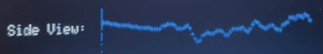
Side view of pond
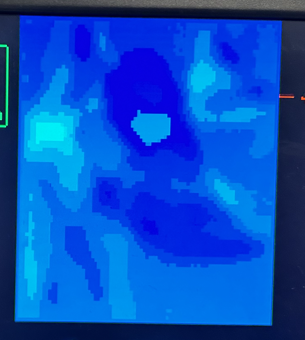
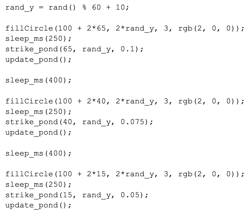
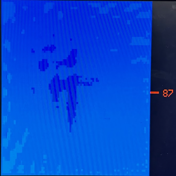
The use of the 8-bit color VGA was because we were modeling heights with color. However, in order to really visualize the water and the motions and ripples that were happening in the water simulation, we added a side view of the pond. The way it worked was by taking all the nodes at one vertical point and taking all the heights that we calculated from the wave equation at that y-point and displaying them. We would calculate the height at which to draw the vertical lines to display the pond by normalizing the value of the height to a range that could be drawn in an area in the VGA screen, as shown in Figure 7.
Figure 7: Side View Calculation
Because we were only displaying the nodes at one y-point, we also added a cursor that would let you determine which image of the water the user would like to display, so which y-position. The way it worked in the code was by using the button to set the cursor_height, and then drawing the nodes only in the cursor_height position, as shown below. The button presses would be registered using the gpio_set_irq_enabled_with_callback() function, so when the button was pressed, the GPIO pin corresponding to the button would register this and cause the program to go into the function down_button_pressed(), which simply incremented the cursor_height variable and redrew the cursor rectangle, as shown in Figure 8.
Figure 8: Side View Drawing
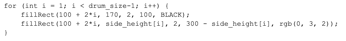
We tried different ways of displaying this side view of the pond. The two versions that we were thinking of using fillCircle or fillRect to draw the water at its height. The value of side_height would be the same for both, but we were debating which one adds the most to our water simulation. We ultimately decided to use fillRect because it displayed the water as if we were now half submerged in the pond and half not, so we could see the waves in the water and see how sometimes parts of the water were under or above the central line at 0. A very interesting phenomenon that we would observe was when there were overlapping waves, which was something we could only see with the side view. Figure 11 clearly depicts the value that this side view adds to our simulation, both for us and the person viewing the simulation.
Figure 9: Side View using fillCircle()
Figure 10: Side View using fillRect()
Figure 11: Beautiful Side View of Pond with Many Strike Interactions
Skipping Stone
All of the computation that has been described up to this point was done in the main thread of Core 0. We also used Core 1 to deal with the skipping stone portion of the project. To skip stones, we added the IMU to our project. The first thing we did was configure the PWM to periodically prompt an interrupt. This interrupt is what would record the acceleration and gyroscope data that comes out of the IMU. This meant that every period, the program would receive the data from the IMU. The period was small enough that the program was working smoothly to human input. The RP2040 and the IMU communicated with each other through the I2C communication protocol. Therefore, data would move from the IMU to the RP2040, where we would determine whether the z-direction acceleration that we recorded was greater than 1.9G. The acceleration threshold of the IMU was 2.0G, so we tried configuring the IMU to have its threshold at 4.0G. However, we realized that it was very difficult to snap the IMU to accelerate with such a large force.
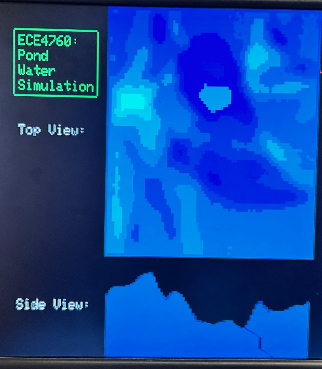
Therefore, if the program registered a z-direction acceleration greater than 1.9, the stone skipping thread in Core 1 would reuse the strike_pond() function that we used to get the static water simulation. However, the strike_pond() that we used in this thread would get a random position to throw the stone in and it would have a weaker strength parameter. Figure 5 shows that the strike pond function uses the strength parameter to see by how much to change the strength. We set the strength of the stone skipping strikes to be weaker than the initial “natural” strikes. To model stone skipping, we also animated it so that we could observe three strikes with three stone drawings with some delay so that it looks like it is one stone moving across the pond. To make it even more realistic, for each throw, we reduce each subsequent stone strength. In our case, we say that the one stone skips three times, so the first strike is strength 0.1, the second strike is strength 0.075, and the third strike is strength 0.05. Figure 12 shows the implementation of the randomized skipping, along with the stone animation and striking.
Figure 12: Stone Skipping Animation
To summarize, the user would grab the IMU, snap it, and then the screen would display the stone moving through the water, along with the changing depths of the water at the points where the strikes happened.
Video 4: Clear Stone Skipping
Serial Communication with Putty
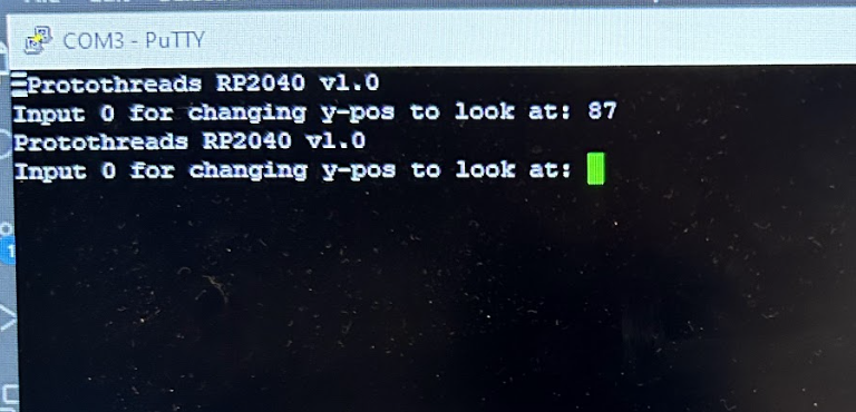
We also had a separate thread that ran in Core 1 that used the UART communication protocol to communicate with the serial terminal Putty. We used it a lot throughout our debugging process, but we ultimately decided to use it to add another form of choosing which y-position to look at for the side view. One disadvantage that we observed when using the button to choose the cursor_height, we realized that it was a bit difficult to keep pressing the button to get to the other end of the pond. Therefore, the serial communication would allow us to jump between cursor heights instead of incrementing, thus making a smoother demonstration process. Putty would print out “Input 0 for changing y-pos to look at:” and based on the input, the variable cursor_height would change accordingly. It is worth to note that there could be extensions to our serial communication using Putty to enhance the demonstration portion of our project. For example, we could let the user set all the nodes’ height to zero or let the user strike the pond wherever they want. There are many extensions that we did not have the time to implement, but that would facilitate the process of seeing the ripples clearly.
Figure 13: Putty Demonstration
Overall, the end result of our project exceeded the initial expectations and vision we had for the simulation. Since we were trying to imitate a natural phenomenon, it was relatively difficult to determine and measure the accuracy and precision of our simulation. Instead, we had a holistic and subjective interpretation of the accuracy of the simulation. The main goal with our simulation was to create something that felt as organic as possible where it was difficult to tell that the simulation was dictated by equations. As a result, this required us to induce as much “controlled chaos” as possible which we did by including two initial “pond drops” in the upper left quadrant of the pond. By taking this approach, it meant that the first few seconds (~3-5) of our simulation did feel rather inorganic since the entire plane remained static at a depth of 0 as the two ripple responses propagated throughout the pond. However, once these ripples did eventually reach the border of our pond and started propagating the opposite direction, it began to look more organic.
Video 5: Initial Strikes (first few seconds of animation)
Even though we were able to emulate a pretty realistic pond, since we are still using equations to govern the behavior of the depth of things, there were still some cases where it was obvious that the observed behavior was not intended. This was especially noticeable when our algorithm would propagate the pond upwards and simultaneously we would strike the pond, which immediately decreases the depth of the pond. This immediate reduction sometimes caused parts of the pond to instantly reverse colors, appearing as if someone had pressed a rewind button in the middle of our simulation. (This behavior was very uncommon so we did not decide to take it into consideration when tuning our system.)
Video 6: Reversal Behavior
Despite these minor drawbacks to our simulation, the overall response and behavior of our system worked well. According to the feedback we received from people who tested out our simulation, they noted that the rock skipping response looked very nice as sometimes they were able to notice the ripple waves really propagate throughout the pond. Additionally, they noted that the bottom graph we had to display a horizontal slice of the varying heights was very helpful to better understand what the changing colors in our pond simulation above represented. However, when showing it to people, we did receive feedback that even though they were snapping the IMU, the water simulation was not displaying the three ripples. We took into consideration and analyzed why this behavior was occurring. Even though the ripples were not appearing, the rock simulation was, which meant that the stone skipping functions were all called. We realized that when the heights of the water were already low enough, the strikes did not alter the height of the pond since it was just keeping those nodes at their original heights. Although it did not look as we intended, it made sense in the “natural” sense, so we did not modify it.
In terms of enforcing safety in design, there were two aspects we had to take into consideration; the physical hardware safety, and also the design of our code. Since we were mostly working with things that did not require insane amounts of power or current, putting everything together on one board and close to each other was a valid design approach. (We did not need to isolate any system from another.) As per our code, we did have to take into consideration some elements of concurrency in our design, making sure that we did not have two threads or two methods operating on the same code space. (We made sure that only one method would update a variable, and all other threads would only read that variable to reduce the probability of running into race conditions.)
General Reflections and Learnings
This final project proved to be filled with numerous challenges and also a great deal of research of new topics that we had not previously seen. We felt that our final simulation massively exceeded our expectations as we felt that we created a pond simulation that accurately represented what someone would see if they were to skip rocks on a pond.
Throughout this project, we learned a lot about the hardware and software we used in the first couple of labs. We had to experiment with the hsync.pio, vsync.pio, and vga256_graphics.c files to accurately understand how the color mappings worked and how the Lab 2 VGA files differed from the 8-bit color VGA files. We also got a better understanding of how the PWM worked and why we used it in Lab 3. We realized its usefulness when trying to induce periodic interrupt signals that substantially reduce the computation needed to be done by the cores, but still accurately registers data induced by human input.
Further Improvements
We felt that we wouldn’t do things differently in the future as the end product exceeded expectations, but there are plenty of things we would further incorporate to improve our simulation. Currently, our rock strikes were very uniform as it would always strike down in a pyramid shape with linearly changing depths. To increase variability, it would be interesting to observe what would happen if we had some other nonlinear strike to see how the responses would change.
Another feature we could add which would improve the “accuracy” of our pond would be to add in obstacles in the pond (like a large boulder in different areas) where it would add additional boundaries where the ripple response would bounce off of, increasing the variability once again.
Additionally, we could make the entire project into a small game where there would be an actual character on the screen. Outside the water, there could be grass, and the character would be able to move around the grass and pick up stones. Then, with the stones that it picked up, the character could skip stone. If the character runs out of stones, it will need to go pick up more. At that point, the game could expand anywhere and many cool new capabilities could be added.
Intellectual Property Considerations
Most of our code was created by ourselves, with the exceptions of some formulas to model the wave equation that were taken from the ECE 5760 drum lab source code. We also did follow some hardware layout from Bruce Land’s 8-Bit VGA driver demo which was provided on our course website. Aside from these, everything else was original.
Conformation to Standards
To our knowledge, our project did not violate any applicable standards or other codes of conducts relating to project development using microcontrollers.
Inclusion on course page
The group approves this report for inclusion on the course website.
Inclusion on YouTube channel
The group does not approve the video for inclusion on the course youtube channel.
For the final project, we did a lot of pair programming together and also worked on the lab separately at times. The following represents the general breakdown of the delegation of tasks:
/* ECE 4760 Final Project - Pond Water Animation
* Tomas Choi (tic3) and Matthew Hui (mmh257)
*
* HARDWARE CONNECTIONS
* 8-bit VGA Driver connections
* Source: Bruce Land
*
* --------------
* - GPIO 16 ---> VGA Hsync
* - GPIO 17 ---> VGA Vsync
* --------------
* - GPIO 08 ---> 330 ohm resistor ---> VGA Blue lo-bit |__ both wired to 150 ohm to ground
* - GPIO 09 ---> 220 ohm resistor ---> VGA Blue hi_bit | and to VGA blue
* --------------
* - GPIO 10 ---> 1000 ohm resistor ---> VGA Green lo-bit |__ three resistors wired to 100 ohm to ground
* - GPIO 11 ---> 680 ohm resistor ---> VGA Green mid_bit | and to VGA Green
* - GPIO 12 ---> 330 ohm resistor ----> VGA Green hi_bit |
* --------------
* - GPIO 13 ---> 1000 ohm resistor ---> VGA Red lo-bit |__ three resistors wired to 100 ohm to ground
* - GPIO 14 ---> 680 ohm resistor ---> VGA Red mid_bit | and to VGA red
* - GPIO 15 ---> 330 ohm resistor ----> VGA Red hi_bit |
* --------------
* - RP2040 GND ---> VGA GND
*
* MPU6050 Accelerometer Connections:
*
* --------------
* - GPIO 26 ---> MPU6050 SDA
* - GPIO 27---> MPU6050 SCL
* - 3.3v ---> MPU6050 VCC
* - RP2040 GND ---> MPU6050 GND
* --------------
*
* Serial Terminal Connections:
*
* --------------
* GPIO 0 ---> White
* GPIO 1 ---> Green
* RP2040 GND ---> GND
*
* GPIO Button Connections:
*
* --------------
* GPIO 21 ---> button
* RP2040 GND ---> button
* --------------
*
* RESOURCES USED
* - PIO state machines 0, 1, and 2 on PIO instance 0
* - DMA channels 0, 1
* - 153.6 kBytes of RAM (for pixel color data)
* - Numerous GPIO Channels listed above
*
*/
// Include the VGA grahics library
#include "vga256_graphics.h"
// Include standard libraries
#include <stdio.h>
#include <stdlib.h>
#include <math.h>
#include <string.h>
// Include Pico libraries
#include "pico/stdlib.h"
#include "pico/divider.h"
#include "pico/multicore.h"
// Include hardware libraries
#include "hardware/pio.h"
#include "hardware/dma.h"
#include "hardware/clocks.h"
#include "hardware/irq.h"
#include "hardware/adc.h"
#include "hardware/i2c.h"
#include "hardware/pwm.h"
#include "hardware/spi.h"
// Include protothreads
#include "pt_cornell_rp2040_v1_1_1.h"
// Include MPU6050 library
#include "mpu6050.h"
// === the fixed point macros ========================================
typedef signed int fix15;
#define multfix15(a, b) ((fix15)((((signed long long)(a)) * ((signed long long)(b))) >> 15))
#define float2fix15(a) ((fix15)((a)*32768.0)) // 2^15
#define fix2float15(a) ((float)(a) / 32768.0)
#define absfix15(a) abs(a)
#define int2fix15(a) ((fix15)(a << 15))
#define fix2int15(a) ((int)(a >> 15))
#define char2fix15(a) (fix15)(((fix15)(a)) << 15)
#define divfix(a, b) (fix15)(div_s64s64((((signed long long)(a)) << 15), ((signed long long)(b))))
// drum-specific multiply macros simulated by shifts
#define times0pt5(a) ((a) >> 1)
#define times0pt25(a) ((a) >> 2)
#define times2pt0(a) ((a) << 1)
#define times4pt0(a) ((a) << 2)
#define times0pt9998(a) ((a) - ((a) >> 12)) //>>10
#define times0pt9999(a) ((a) - ((a) >> 13)) //>>10
#define times0pt999(a) ((a) - ((a) >> 10)) //>>10
#define times_rho(a) (((a) >> 3)) //>>2
// Frame Rate to assist with tracking time spent in threads
#define FRAME_RATE 33000
// Created pixel struct to store information on each pixel
typedef struct
{
fix15 x_pos;
fix15 y_pos;
fix15 height_n; //current height
fix15 height_n_1; //previous height
fix15 new_height; //newly calculated height
char color;
} pixel;
// Drum sizing parameters from ECE5760 Lab 3
// drum will FAIL if size is too big
// Determined drum_size experimentally, looking for the maximum value before we exceeded the ram limits
#define drum_size 85
#define drum_middle 15
// Number of total pixels in the simulation: 85x85
#define num_pixels 7225
pixel pond[drum_size][drum_size]; //30x30 board for now
// state variables for pond calculations
fix15 new_pond_temp;
//Counter variable for the timer stuff
int time_count = 0;
// Variable used to keep track of text to write onto the VGA Screen
char text[50];
// Arrays in which raw measurements will be stored
fix15 acceleration[3], gyro[3];
// semaphore
static struct pt_sem vga_semaphore ;
// Some paramters for PWM
#define WRAPVAL 5000
#define CLKDIV 25.0
uint slice_num ;
// State variables used in the side view rendering
// Keeps track of the current y-axis level view of the pond
int cursor_height = 40;
// Temporary variable keeping track of heights from the side view
fix15 side_height[drum_size];
// GPIO Button routine: Moves the cursor height down by 1, once we reach the end
// of the pond, it wraps back towards the top resetting it to a height of 0.
void down_button_pressed () {
cursor_height++;
if (cursor_height > 2*85){
cursor_height = 0;
}
fillRect (100, 170, 170, 50, BLACK);
}
// Interrupt service routine for MPU6050
void on_pwm_wrap() {
// Clear the interrupt flag that brought us here
pwm_clear_irq(pwm_gpio_to_slice_num(19));
// Read the IMU
mpu6050_read_raw(acceleration, gyro);
// Signal VGA to draw
PT_SEM_SIGNAL(pt, &vga_semaphore);
}
//Initializing the pond board to a base shade of blue - rgb(0, 3, 2)
void init_board()
{
for (int i = 0; i < drum_size; i++)
{
for (int j = 0; j < drum_size; j++)
{
//Start off with spacing them 1 pixel apart
pond[i][j].x_pos = int2fix15(100 + 2 * i);
pond[i][j].y_pos = int2fix15(2 * j);
pond[i][j].height_n = int2fix15(0);
pond[i][j].height_n_1 = int2fix15(0);
pond[i][j].new_height = int2fix15(0);
pond[i][j].color = rgb(0, 3, 2); //start off blue
fillRect(fix2int15(pond[i][j].x_pos), fix2int15(pond[i][j].y_pos), 2, 2, rgb(0, 3, 2));
}
}
}
// Water strike method - visualized as setting an area in the pond to some arbitrary pyramid like height shape
// Takes in 3 parameters:
// int x, y: Coordinates of the strike location
// float strength: The maximum height the middle of the strike will be, should range between [0,1]
// Note: The method is additive, adding the strike height onto the existing pixels, with
// the strike strength descending linearly from the central strike onto the neighboring 5 pixels
void strike_pond(int x, int y, float strength)
{
//Initial setup variables
static int i = 0;
static int j = 0;
static int squared_distance = 0;
static int x_dist = 0;
static int y_dist = 0;
static int dist_level = 0;
static float new_height = 0;
//NOTE: i -> y coordinates, j -> x coordinates
//Looping through the current pixels in the pond, setting the peaks of the values
//The value of the peaks will range from [-1,1]
for (i = 0; i < drum_size; i++)
{
for (j = 0; j < drum_size; j++)
{
x_dist = abs(i - x);
y_dist = abs(j - y);
dist_level = fmax(x_dist, y_dist);
//Checks for the pixels that are within a 5 pixel radius (Manhattan Distance)
if (dist_level <= 5)
{
new_height = (float)(5 - dist_level) / 5.0 * strength;
pond[i][j].height_n = float2fix15(fix2float15(pond[i][j].height_n) + new_height);
pond[i][j].height_n_1 = float2fix15(fix2float15(pond[i][j].height_n_1) + new_height);
}
}
}
}
// Helper method: Deep copy information from height_n_1 onto height_n.
// Utilized since deep copying needs to occur once we fully modify every pixel in the pond
// in its current state
void copy_data()
{
static int i = 0;
static int j = 0;
for (i = 0; i < drum_size - 1; i++)
{
for (j = 0; j < drum_size - 1; j++)
{
pond[i][j].height_n_1 = pond[i][j].height_n;
pond[i][j].height_n = pond[i][j].new_height;
}
}
}
// Updating Pond Method: Performs the wave equation algorithm onto the entire
// pond, updating the values based on neighboring ones and any strikes on the pond.
// The magnitude of heights will range between [-1,1]
void update_pond()
{
static int i = 0;
static int j = 0;
//Iterate through all the pixels EXCEPT the right and bottom wall
for (i = 1; i < drum_size - 1; i++)
{
for (j = 1; j < drum_size - 1; j++)
{
//Wave equation logic
new_pond_temp = times_rho(pond[i - 1][j].height_n + pond[i + 1][j].height_n + pond[i][j - 1].height_n + pond[i][j + 1].height_n - times4pt0(pond[i][j].height_n));
pond[i][j].new_height = times0pt9999(new_pond_temp + times2pt0(pond[i][j].height_n) - times0pt9998(pond[i][j].height_n_1));
//Coloration setting logic: Setting the color of a pixel based on its height
if (pond[i][j].height_n > float2fix15(0.15) && pond[i][j].height_n < float2fix15(0.2))
{
pond[i][j].color = rgb(0, 7, 2);
}
else if (pond[i][j].height_n > float2fix15(0.1) && pond[i][j].height_n <= float2fix15(0.15))
{
pond[i][j].color = rgb(0, 6, 2);
}
else if (pond[i][j].height_n > float2fix15(0.05) && pond[i][j].height_n <= float2fix15(0.10))
{
pond[i][j].color = rgb(0, 5, 2);
}
else if (pond[i][j].height_n > float2fix15(0.0) && pond[i][j].height_n <= float2fix15(0.05))
{
pond[i][j].color = rgb(0, 4, 2);
}
else if (pond[i][j].height_n > float2fix15(-0.05) && pond[i][j].height_n <= float2fix15(0))
{
pond[i][j].color = rgb(0, 3, 2);
}
else if (pond[i][j].height_n > float2fix15(-0.1) && pond[i][j].height_n <= float2fix15(-0.05))
{
pond[i][j].color = rgb(0, 2, 2);
}
else if (pond[i][j].height_n > float2fix15(-0.15) && pond[i][j].height_n <= float2fix15(-0.10))
{
pond[i][j].color = rgb(0, 1, 2);
}
else if (pond[i][j].height_n > float2fix15(-0.2) && pond[i][j].height_n <= float2fix15(-0.15))
{
pond[i][j].color = rgb(0, 0, 2);
}
else
{
pond[i][j].color = rgb(0, 5, 2);
}
}
}
//Copy over the values from height_n_1 to height_n
copy_data();
}
// Helper Method: Drawing the top down view of our pond in the top half
// of the screen. Loops through every single pixel and draws a rectangle
// with the corresponding rectangle and color.
void draw_pond_top() {
for (int i = 0; i < drum_size - 1; i++)
{
for (int j = 0; j < drum_size - 1; j++)
{
fillRect(fix2int15(pond[i][j].x_pos), fix2int15(pond[i][j].y_pos), 2, 2, pond[i][j].color);
}
}
}
// Helper Method: Drawing the side view of our pond.
// Parameter:
// int y_coord: Takes in the y-coordinate representing the slice of the pond to visualize
void draw_pond_front(int y_coord) {
//Normalize and scale the height data onto our margins for the graph and convert it to the
//appropriate y-position on the VGA Screen representing this.
for (int i = 0; i < drum_size; i++) {
//Using y = 200 as a midpoint for our graph, 40 pixels of room above and 40 below.
side_height[i] = int2fix15(200) - multfix15(divfix(pond[i][y_coord].height_n, float2fix15(0.2)), int2fix15(225));
}
//Drawing the side view of the pond
for (int i = 1; i < drum_size-1; i++) {
//Clears the previous rendering
fillRect(100 + 2*i, 170, 2, 100, BLACK);
//Draws in a line with the new rendering/height
fillRect(100 + i*2, fix2int15(side_height[i]), 2, 300 - fix2int15(side_height[i]), rgb(0, 3, 2));
//Commented out, but only drew the square at the heights intead of a line downwards to obtain a
//different view
// fillRect(2*i, fix2int15(side_height[i]), 2, 2,rgb(0, 3, 2));
}
}
// Basic pond animation thread
static PT_THREAD(protothread_anim(struct pt *pt))
{
PT_BEGIN(pt);
// Variables for maintaining frame rate
static int begin_time ;
static int spare_time ;
//Initial pond
init_board();
//Adding Text
setCursor(30, 80);
setTextSize(1);
setTextColor(WHITE);
sprintf(text, "Top View: ");
writeString(text);
setCursor(30, 200);
setTextSize(1);
setTextColor(WHITE);
sprintf(text, "Side View: ");
writeString(text);
//More text representing the title of the project
drawRoundRect(26, 16, 67, 45, 1, GREEN);
setCursor(30, 20);
setTextSize(1);
setTextColor(GREEN);
sprintf(text, "ECE4760:");
writeString(text);
setCursor(30, 30);
setTextSize(1);
setTextColor(GREEN);
sprintf(text, "Pond");
writeString(text);
setCursor(30, 40);
setTextSize(1);
setTextColor(GREEN);
sprintf(text, "Water");
writeString(text);
setCursor(30, 50);
setTextSize(1);
setTextColor(GREEN);
sprintf(text, "Simulation");
writeString(text);
while (1)
{
// Measure time at start of thread
begin_time = time_us_32() ;
// Cursor
fillRect(100 + 85*2, 0, 30, 200, BLACK);
fillRect(100 + 85*2, cursor_height, 10, 2, RED);
// Drawing in the cursor height number next to the cursor
setCursor(100 + 85*2 + 10 + 5, cursor_height - 2);
setTextColor(RED);
sprintf(text, "%d", cursor_height);
writeString(text);
//Every 10,000 counts of the thread, we strike the pond twice in the upper left
//quadrant which will provide us with a steady level of chaos induced into our system.
if (time_count == 0) {
strike_pond(20, 0, 0.3);
strike_pond(0, 40, 0.3);
}
update_pond();
time_count++;
if (time_count == 10000) {
time_count = 0;
}
//Calls the draw methods to draw the top and side views
draw_pond_top();
draw_pond_front(cursor_height);
spare_time = FRAME_RATE - (time_us_32() - begin_time) ;
// yield for necessary amount of time
PT_YIELD_usec(spare_time) ;
}
PT_END(pt);
}
//Serial thread to ask for user to inputs to change
//cursor value/location
static PT_THREAD(protothread_serial(struct pt *pt))
{
PT_BEGIN(pt);
// stores user input
static int user_input ;
static int parameter_input ;
static float float_input ;
// wait for 0.1 sec
PT_YIELD_usec(1000000) ;
// announce the threader version
sprintf(pt_serial_out_buffer, "Protothreads RP2040 v1.0\n\r");
// non-blocking write
serial_write ;
while(1) {
// // print prompt
sprintf(pt_serial_out_buffer, "Input 0 for changing y-pos to look at: ");
// non-blocking write
serial_write ;
// spawn a thread to do the non-blocking serial read
serial_read ;
// convert input string to number
sscanf(pt_serial_in_buffer,"%d", &user_input) ;
// update boundary condition
if (user_input == 0) {
sprintf(pt_serial_out_buffer, "Input y-pos to look at: ");
// non-blocking write
serial_write ;
// spawn a thread to do the non-blocking serial read
serial_read ;
// convert input string to number
sscanf(pt_serial_in_buffer,"%d", &user_input) ;
cursor_height = user_input;
}
// END WHILE(1)
PT_END(pt);
}
}
//VGA Display drawing thread
static PT_THREAD (protothread_vga(struct pt *pt))
{
// Indicate start of thread
PT_BEGIN(pt) ;
// Control rate of drawing
static int throttle ;
// Draw the static aspects of the display
setTextSize(1) ;
setTextColor(WHITE);
//Random number generated variables
static int rand_y = 0;
while (true) {
// Wait on semaphore
PT_SEM_WAIT(pt, &vga_semaphore);
//Determining if our measured acceleration is above a threshold before drawing our
//rock skips
if (fix2float15(acceleration[2]) >= 1.99){
//Random logic to determine the random y location to begin our skips
rand_y = rand() % 60 + 10;
//Draws the first rock in the skip cycle and strikes
fillCircle(100 + 2*65, 2*rand_y, 3, rgb(2, 0, 0));
sleep_ms(250);
strike_pond(65, rand_y, 0.1);
update_pond();
//Updates colors around it
for (int i = 0; i < drum_size - 1; i++)
{
for (int j = 0; j < drum_size - 1; j++)
{
if (i!=65) fillRect(fix2int15(pond[i][j].x_pos), fix2int15(pond[i][j].y_pos), 2, 2, pond[i][j].color);
}
}
draw_pond_front(cursor_height);
//Sleeps for 400ms before skipping to the next rock
sleep_ms(400);
//Draws the second rock in the skip cycle and strikes it with a little less power
fillCircle(100 + 2*40, 2*rand_y, 3, rgb(2, 0, 0));
sleep_ms(250);
strike_pond(40, rand_y, 0.075);
update_pond();
for (int i = 0; i < drum_size - 1; i++)
{
for (int j = 0; j < drum_size - 1; j++)
{
if (i!=40) fillRect(fix2int15(pond[i][j].x_pos), fix2int15(pond[i][j].y_pos), 2, 2, pond[i][j].color);
}
}
draw_pond_front(cursor_height);
sleep_ms(400);
//Draws the final rock in the cycle with the least amount of strength
fillCircle(100 + 2*15, 2*rand_y, 3, rgb(2, 0, 0));
sleep_ms(250);
strike_pond(15, rand_y, 0.05);
update_pond();
for (int i = 0; i < drum_size - 1; i++)
{
for (int j = 0; j < drum_size - 1; j++)
{
if (i!=15) fillRect(fix2int15(pond[i][j].x_pos), fix2int15(pond[i][j].y_pos), 2, 2, pond[i][j].color);
}
}
draw_pond_front(cursor_height);
sleep_ms(400);
}
}
// Indicate end of thread
PT_END(pt);
}
//Second core used to animate the rock throwing animations, and also the serial threads
void core1_main()
{
// Add animation thread
pt_add_thread(protothread_vga);
pt_add_thread(protothread_serial);
// Start the scheduler
pt_schedule_start;
}
//Main method
int main()
{
// initializing stio
stdio_init_all();
// initializing the VGA
initVGA();
////////////////////////////////////////////////////////////////////////
///////////////////////// I2C CONFIGURATION ////////////////////////////
i2c_init(I2C_CHAN, I2C_BAUD_RATE) ;
gpio_set_function(SDA_PIN, GPIO_FUNC_I2C) ;
gpio_set_function(SCL_PIN, GPIO_FUNC_I2C) ;
// MPU6050 initialization
mpu6050_reset();
mpu6050_read_raw(acceleration, gyro);
////////////////////////////////////////////////////////////////////////
///////////////////////// PWM CONFIGURATION ////////////////////////////
////////////////////////////////////////////////////////////////////////
// Tell GPIO's 19,18 that they allocated to the PWM
gpio_set_function(19, GPIO_FUNC_PWM);
gpio_set_function(18, GPIO_FUNC_PWM);
// Find out which PWM slice is connected to GPIO 19 (it's slice 2, same for 18)
slice_num = pwm_gpio_to_slice_num(19);
// Mask our slice's IRQ output into the PWM block's single interrupt line,
// and register our interrupt handler
pwm_clear_irq(slice_num);
pwm_set_irq_enabled(slice_num, true);
irq_set_exclusive_handler(PWM_IRQ_WRAP, on_pwm_wrap);
irq_set_enabled(PWM_IRQ_WRAP, true);
// This section configures the period of the PWM signals
pwm_set_wrap(slice_num, WRAPVAL) ;
pwm_set_clkdiv(slice_num, CLKDIV) ;
// This sets duty cycle
pwm_set_chan_level(slice_num, PWM_CHAN_B, 0);
pwm_set_chan_level(slice_num, PWM_CHAN_A, 0);
// Start the channel
pwm_set_mask_enabled((1u << slice_num));
// Button pressing gpio
gpio_set_irq_enabled_with_callback(21, GPIO_IRQ_EDGE_RISE, true, &down_button_pressed);
// start core 1
multicore_reset_core1();
multicore_launch_core1(&core1_main);
//Add thread to the core 0
pt_add_thread(protothread_anim);
// starting the thread scheduler
pt_schedule_start;
}