High-Level Design
In this project, we embarked on an innovative journey to design and develop a motion-controlled interface for playing tic-tac-toe on a VGA screen. The system, powered by two RP2040 microcontrollers, integrates physical motion tracking with digital game mechanics. One microcontroller, equipped with a MPU6050 sensor and Bluetooth module, functions as a dynamic motion controller. The other, serving as the master unit, manages the VGA display and the core game logic. Our focus was on creating a seamless and intuitive gameplay experience, utilizing the motion data from the MPU6050 sensor for cursor movement and leveraging Bluetooth for data transfer.
This project presented a challenging blend of hardware interfacing and software development while also offering a unique platform to explore the synergy between physical interaction and digital entertainment in gaming.
This project is important for us as we believe that combining the physical and virtual interactions may be very helpful in the case of assisting children in movement skills as well as mental awareness, in a playful way. Furthermore, the project’s interface design can also possibly help to facilitate people with special needs. One example could be people with missing body parts would be able to play games they normally couldn’t. With its simplicity, the game could become an inclusive tool that is accessible, educative, and entertaining to learners from different age groups and with diverse abilities. This project has the possibility to not only give people entertainment but also makes gaming more inclusive.
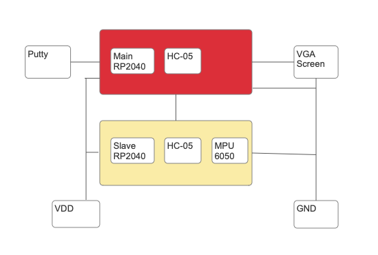
Figure 1 presents an overview of our project. It consists of the main Pico RP2040 that is connected with the master HC-05 bluetooth module, Putty for serial communication and the VGA screen. The second block consists of another Pico RP2040 that is connected to the slave HC-05 bluetooth module and a MPU6050 sensor.
We created a wireless controller that is used to interact with a menu which is displayed on the VGA screen. A player first sets a reference point by pointing towards the screen and press confirm, this helps setting a reference point for movement calculations. Then the player uses the motion controller to move the cursor by pointing directly at the VGA screen and moving the controller. The player can then select the start game menu item to begin the tic tac toe game. The other menu items displayed do not have any functionality, but if the group had more time the player could also choose between single player and multiplayer as well as change the settings for the game. The player can then start by making the first move of the game. After the player has made its move, the game will toggle players and the other player takes the controller and places his move. Using this cursor and inputting a command to Putty, the players can select which box to place its character in.
The controller is only able to sense movement from the IMU and is directly communicating with the main PICO which handles the logic for computing where to display the cursor, given the positional information from the controller PICOs. The main pico also handles the game logic, meaning deciding whose turn it is, displaying the board and deciding the winner. Communication between the controller and the main PICO is done by transferring data with the use of bluetooth modules. The bluetooth protocol follows a master-slave implementation. As such, the master PICO is the PICO directly responsible for the outputs. The slave is the controller which would like to connect to the main PICO and is the one processing measurements from the IMU.
The MPU6050 plays a pivotal role in this project. It is a combined 6-degree of freedom (DoF) sensor that integrates a 3-axis gyroscope and a 3-axis accelerometer. However, in this particular implementation, the focus is primarily on the gyroscope component for motion tracking. The gyroscope in the MPU6050 is a MEMS (Micro-Electro-Mechanical Systems) gyroscope. Meaning that it operates based on the Coriolis Effect.
This effect is a fundamental principle in physics that explains how the movement of a vibrating mass is influenced when it is subjected to rotational motion. Here’s a detailed look into how this works and its implications in the context of gyroscopes.
The Coriolis Effect describes how a moving object appears to follow a curved path when observed from a rotating frame of reference. In the case of gyroscopes in MEMS devices, a tiny mass is made to vibrate along a straight path. When the device is rotated, the path of this mass appears to deviate due to the Coriolis force. In our gyroscope, a mass is set into oscillation. When the gyroscope rotates, the Coriolis force acts on the vibrating mass, causing it to move perpendicular to both its direction of vibration and the axis of rotation. This perpendicular movement is detected by capacitive sensors within the MEMS structure, which then convert it into an electrical signal. The intensity of this signal is proportional to the rate of rotation.

The cross product yields a vector perpendicular to both the velocity of the vibrating mass and the rotation axis, indicating the direction of the Coriolis force.
The math regarding the gyroscope is straightforward. As noted, it directly measures rotation rate. So, if we know the initial angle for our system (𝜃o) and our sample rate (1/Δ𝑡)), we can use the gyroscope to integrate that angle for all time.
The advantage is that gyroscopes are less noisy than accelerometers in the short term. They provide smoother and more stable readings for small, quick movements. For this project, this means that the cursor movements on the VGA display will be fluid and responsive to small, quick motions of the controller. This allows players to make precise selections on the VGA screen with minimal latency or overshoot, enhancing the gameplay experience.
However, over time, gyroscopes tend to drift, leading to accumulated errors in angle estimation. This phenomenon, known as gyro drift, is significant in applications requiring precise and long-term angle measurements.The process we are using, where gyro measurements are integrated over time to estimate the angle, while it's effective in the short term, it inherently accumulates errors over time. This manifests in our project as a slow deviation of the cursor from its intended path, especially noticeable during prolonged usage. In our project, when the controller remains stationary for extended periods, or if the sensor is used continuously over a long duration, this drift could result in the cursor gradually moving or not holding its position accurately.
The gyroscopic data is ideal for the real-time control required in the project, where quick, short movements translate directly to cursor movement on the screen. However, the long-term drift of the gyroscope means that for extended play sessions or if the controller is left idle, the cursor might slowly drift away from its intended position. This necessitates occasional recalibration or resetting of the controller's position to ensure continued accuracy during gameplay.
The MPU6050 measures the force to determine the angular velocity around its three axes (x, y, z). In our code, we are specifically interested in the x-axis (gyro[2]) and the y-axis(gyro[0]), which we scale to obtain a measure of horizontal movement (dx) and vertical movement (dy). The scaling factor adjusts the sensitivity of the cursor movement.
Movement calculations are determined by gyroscopic movement (process_gyro_data_for_x) and (process_gyro_data_for_y). The gyroscope's axis data is scaled to derive the horizontal and vertical movement. This represents how much the device has rotated about the x-axis, corresponding to lateral movement and linear acceleration along the y-axis, corresponding to up and down movement.
Our clamp movement function prevents excessively large movements by setting a maximum limit (max_movement). If the calculated movement exceeds this limit, it is clamped to this maximum value. This avoids sudden large jumps of the cursor on the screen and helps with the user experience.
We then use these calculations to map it to the VGA screen(map_to_screen_coordinates). The relative movements (dx, dy) are scaled according to screen dimensions to map them to screen coordinates (screen_x, screen_y). This mapping ensures that the sensor's movements correspond accurately to movements on the screen. Scaling factors for x and y axes (x_scale, y_scale) are used to control the sensitivity of this mapping. We also have a function that ensures that the resulting screen coordinates do not go off-screen.
The data gathering (getData) function checks if the device is calibrated so we know it's set to a known position which is used as a reference. If calibrated, it reads the current orientation from the MPU6050 and calculates the relative movement, which is then mapped to screen coordinates.
This project leverages the gyroscope data from the MPU6050 to create a motion-controlled interface. The mathematical processing of this data is key, enabling the translation of physical rotations (detected by the MPU6050) into digital cursor movements on a screen with precision and smoothness. This approach focuses solely on gyroscopic data, setting aside accelerometer inputs.
Since our project focused on displaying real time sensor measurements on a screen, our goal was to make the software as fast as possible and the hardware fairly simple. That's the reason we chose a VGA screen, which is a cost-effective solution. However, it limits the resolution and color depth compared to more modern display technologies like HDMI. Secondly, MPU6050 sensor combines both accelerometer and gyroscope, providing fast and comprehensive motion tracking. However, it might not be as accurate as more advanced IMU sensors, especially in environments with lots of vibration or rapid movements. The slowest part of our hardware was the Bluetooth communication. It introduced latency as we couldn't send messages at the same speed as our sensor calculations were made and the outputting to the VGA screen was made.
There weren't many tradeoffs for our software as we used one PICO for sensor calculations and the second one for everything else. Implementing a master-slave Bluetooth communication required careful management of the connection and data transfer. It added complexity to the software but was necessary for wireless communication. Additionally, we couldn't get a button to work with the controller and instead chose to use Putty as an input. This management of the interface on the VGA screen and handling input through both the Putty and the motion controller added complexity to the software. This required efficient UI management to ensure a good user experience. Finally, the system's design prioritizes flexibility but at the cost of increased complexity in both hardware setup and software programming.
Motion Sensing Technology such as Nintendo's Wii, introduced in 2006, was revolutionary for its time due to its motion-sensing technology. Patents protect the technology in the Wii Remote, which combines accelerometers and infrared detection to sense its position in 3D space. Our project's use of the MPU6050 sensor for motion detection is similar in concept but likely differs in implementation and scope, which is crucial in patent law.
Patents may also cover specific game mechanics and the software algorithms used to interpret motion data. However, these are often specific to the games and software developed by the company. Copyrights protect the actual software code. While our project involves writing custom software, it's important to ensure that no proprietary code from existing gaming systems is replicated, which it shouldn't be.
Our project is for educational purposes only and not for commercial gain, so it may fall under "fair use". However, this doesn't automatically exempt it from IP laws, especially if it were to be commercialized in the future. A thing worth noting is that if our project introduces novel methods or implementations that significantly differ from existing patented technologies, it might be an innovation in its own right.
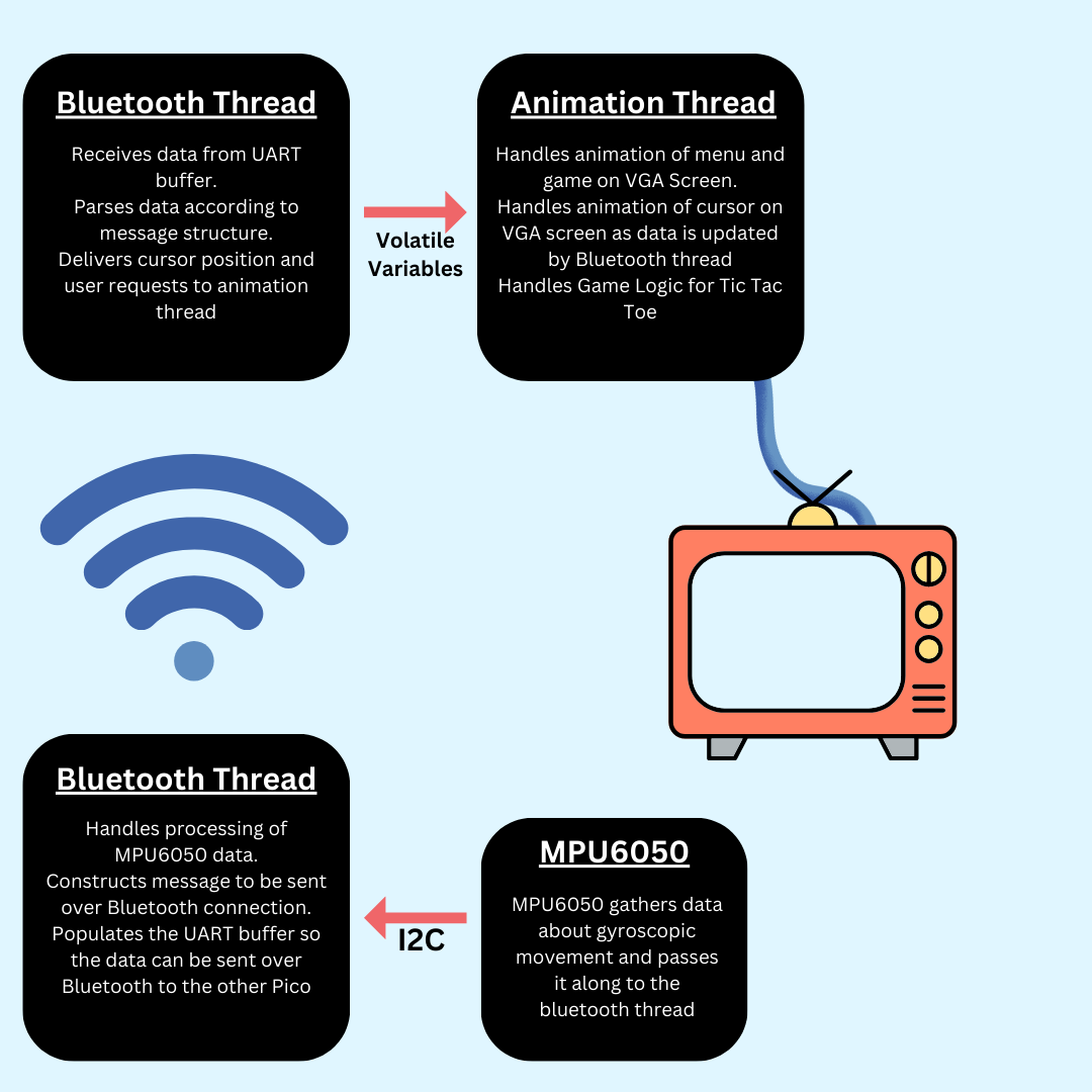
The main code where our program comes together incorporates two threads. One thread is responsible for communicating with the bluetooth module. This thread exists on its own in case UART communication blocks execution of the core. The menu state, menu inputs, and drawing to the VGA screen is handled by a separate thread on core 1. Since this thread handles the menu, it also calls the necessary functions to begin the tic tac toe game if the appropriate menu item is selected. As a result, this thread also handles all game logic, as a sort of game engine for the tic tac toe game. Once the game is completed, the function which starts the game returns. This allows the input function to return, allowing the device to return to a state with the menu displayed. At this point, the game can be replayed as before by clicking on the appropriate start game button. Overall implementation of the main section of code required a bit of debugging as this is where all of our other modules were integrated together. As a result, slight modifications were made to the main file as more modules were added. The following is a general overview of how different threads interacted with each other:
The game starts with initializing the global board array, which represents the Tic Tac Toe grid. This array holds values indicating the state of each cell (EMPTY, PLAYER_X, or PLAYER_O). The drawField function visually constructs the game board on a VGA display by drawing vertical and horizontal lines to create a 3x3 grid.
Players use a controller to move a cursor on the VGA screen, whose cursor's position is determined by the MPU6050 sensor data processed by the controller Pico. When a player makes a move by aligning the cursor to a desired cell and confirming it in Putty , the program translates the cursor's screen coordinates into the corresponding cell on the Tic Tac Toe board. The playerMove function then updates the board array with the player's symbol, X or O, based on the cursor's position. It also alternates between players after each move, handled by toggling currentPlayer between PLAYER_X and PLAYER_O.
The displayBoard function continuously updates the VGA display with the current state of the game board, including any 'X's or 'O's placed by the players. The checkWinner function checks for winning conditions after each move. It scans rows, columns, and diagonals to see if either player has aligned their symbols in a line. If a winner is found or the board is full (isBoardFull), the game concludes, displaying the result on the VGA screen and announcing the winner or declaring a draw.
The only challenge was managing the game state and then connecting the game with our other files. Toggling between players and updating the game board after each move, required careful programming to avoid errors and ensure a good user experience.
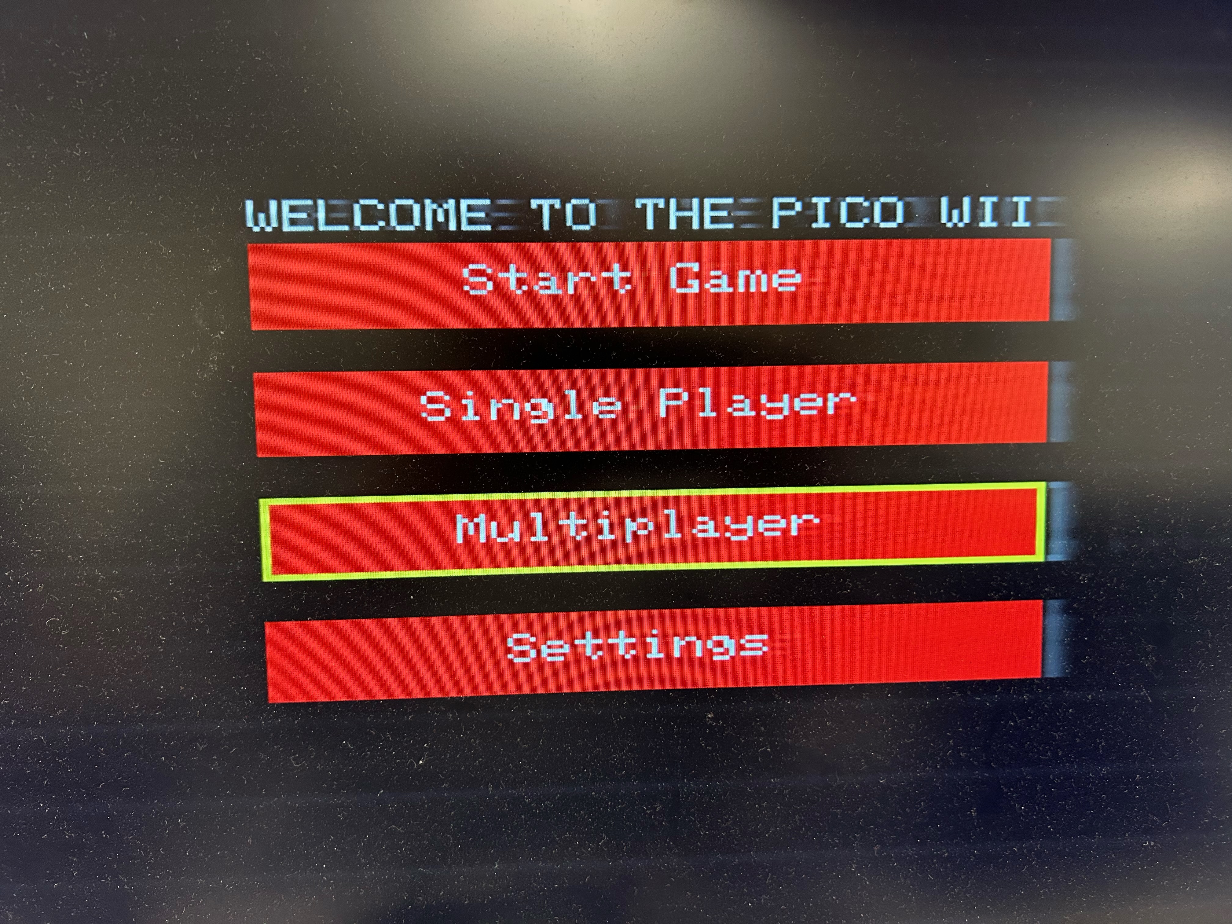
The menu was designed to be extensible in a software sense. This meant the menu is almost entirely contained to itself, with the exception of any VGA drawing elements which were imported from the VGA graphics library created by Professor Hunter. The menu was designed to be extensible in case multiple levels of the menu were needed. One example would be if we wanted a menu item to take us to an entirely different settings menu. The menu is composed of a bounding box in which menu items are drawn within. This is how you can control how large your menu is, as menu items are drawn according to the dimensions of the menu’s bounding box. The menu has a set center pointer that is decided on creation of the menu struct. Each menu could contain at most four menu items, which were stored in an array of menu item structs. The Menu Item struct contains information about the title of the menu item and what action would be taken if the menu item was clicked. This allowed menu items to “store” functions that could be used to call other functionality (perhaps even another menu).
The most difficult part of creating the menu system was deciding how to draw each menu item according to the menu’s bounding box and center point. This was especially difficult because the menu was designed to take any number of menu items between 1 and 4. Thus, the number of menu items in the menu affected how the items were drawn to the screen. As an example, one item would be centered in the width and height of the bounding box. However, four items would essentially take up the entire bounding box and were placed in such a way that centered all four items within the height and width of the bounding box. The second most difficult part of creating the menu system was implementing how the menu system would handle input from the cursor. This is because no information is stored about the actual boxes of the menu items, so these calculations had to be done so the menu could know where a cursor should be to be considered a valid input. This difficulty was compounded by the fact that a menu could hold 1-4 items, so each case had to be handled.
The following is a photo of the menu system:
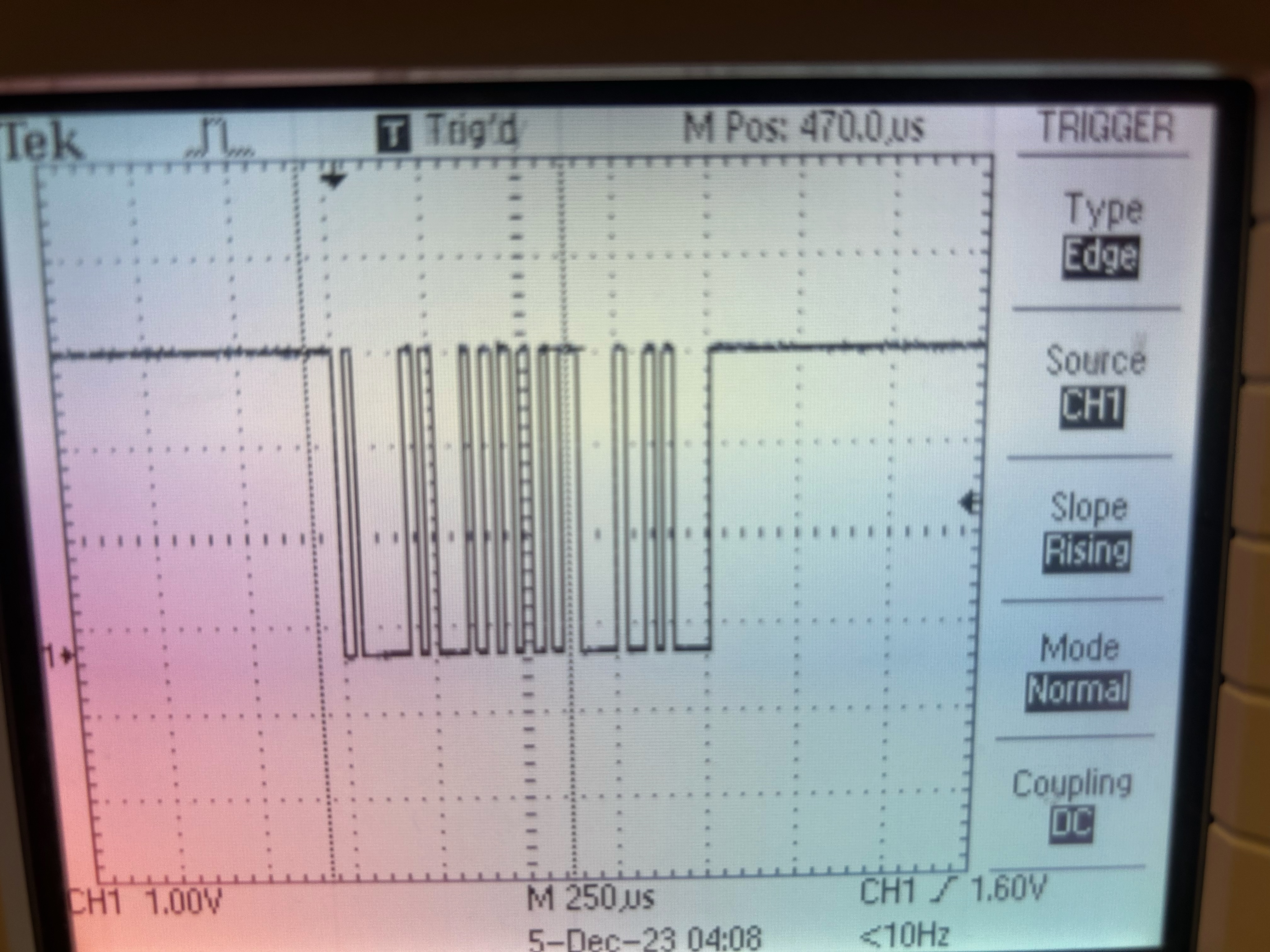
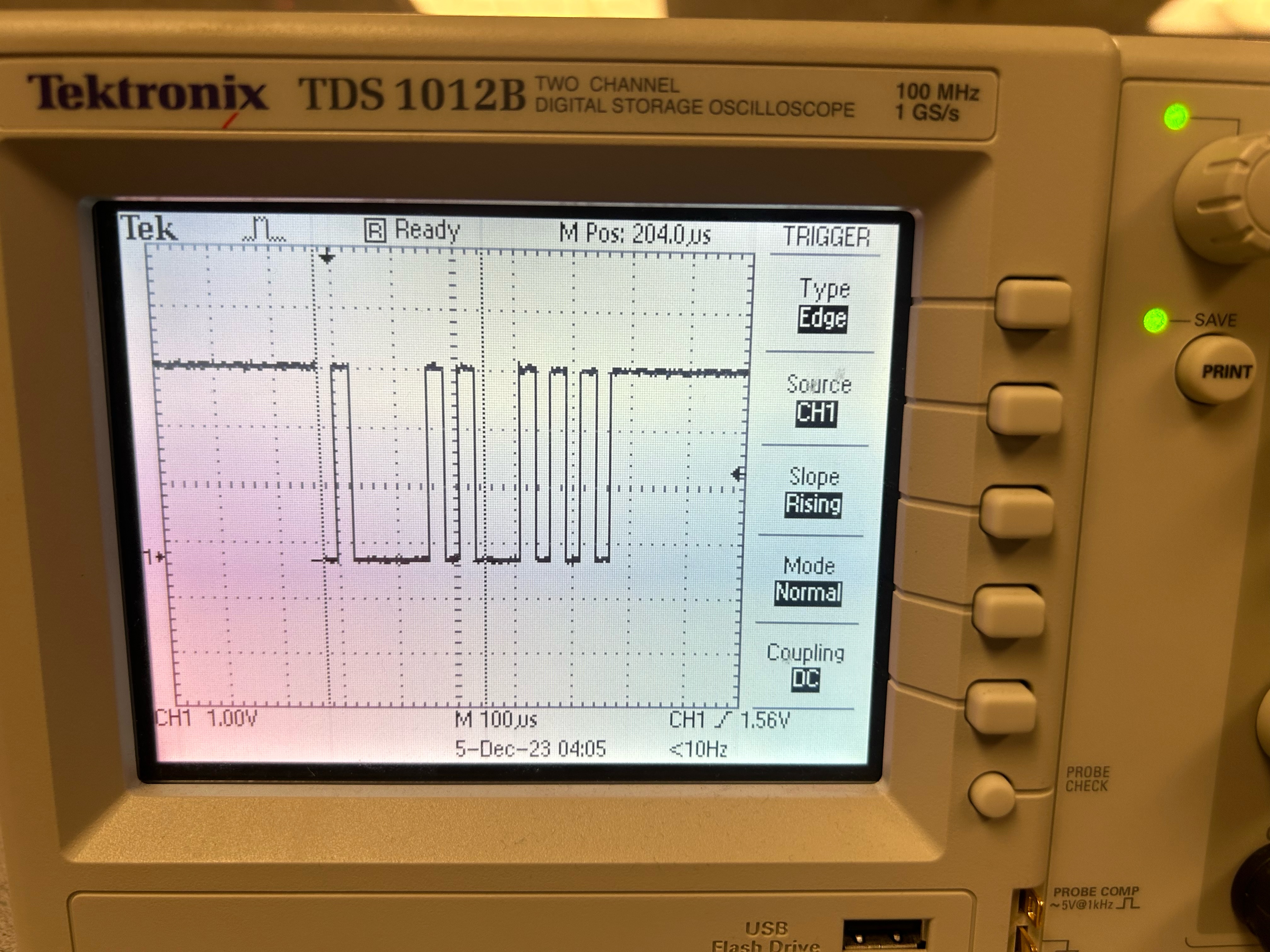
The overall bluetooth system is somewhat simple, but the implementation was difficult and probably where the group faced the most issues. The bluetooth system works by writing UART messages to a UART channel connected to the bluetooth module. The bluetooth module will then take any messages it receives on the UART channel and output it over radio frequency to the connected “slave” bluetooth module. So that these modules only speak to each other, some basic setup was done to bind the main bluetooth module to the slave module on the other Pico. Incorporating the bluetooth modules into our system was especially difficult. Two issues arose which essentially blocked progress on the project until they could be resolved. The first was the initial attempt at communicating with one bluetooth module. This issue was more of a puzzle than it was an actual issue. This is because our original idea for testing and setting up the bluetooth modules was to have a Pico connected to a PuTTY interface where we could input commands to be sent to another UART connection which was connected directly to the bluetooth module. However, due to the way the UART serial interface was programmed, the commands being sent to the bluetooth module were not being recognized. The group did not realize this until later. To ensure the bluetooth module was working correctly, the group manually sent commands hardcoded within the Pico. This ended up working, which shed a little bit of light as to why the previous attempt was unsuccessful. To further ensure the UART signals being sent to the device were different, the UART connection was attached to an oscilloscope. As seen in the following figures, it is evident that the messages being sent are different (even though they were not supposed to be!).
The sensor file was complex to implement and involved navigating various challenges. As touched on above, the bluetooth system gave us issues and integrating the sensor code with other components like Bluetooth, was a challenge and required a comprehensive understanding of how these components interact. We had to ensure compatibility and smooth data flow between these components. Ensuring that the system responded to movements in real-time was another focus. Any latency or delay could disrupt the user experience. We worked with this in a previous laboratory for this course, which definitely helped.
Another part of this section was the fine tuning of the scale factors for gyroscopic data. The implementation wasn't hard but it was crucial to balance sensitivity and control. Too high a scale factor could lead to overly sensitive cursor movements, whereas too low could render the controller unresponsive. Striking this balance was a trial-and-error process requiring multiple iterations. This was a part of developing an intuitive control scheme that felt natural to the users.
Finally, the biggest challenge was to gather the readings from the gyroscope and convert them to meaningful data. The gyroscope is the centerpiece for detecting and translating physical movements into digital signals. Unlike typical implementations that might combine gyroscope and accelerometer data, our approach uniquely focuses on gyroscopic data alone. Initially, there was an attempt to incorporate accelerometer data to complement the gyroscope readings or give us measurements for the y-axis. However, the data we got did not match what we wanted and this led to the decision to rely solely on gyroscopic data.
As touched on in the mathematical background section, a significant challenge in gyroscopic data processing is addressing gyro drift. Over time, the integration of angular velocity to estimate the angle can accumulate errors, leading to drift. This was observed as a slow deviation of the cursor from its intended path, especially noticeable during extended use. It was addressed through frequent calibration and careful mathematical processing, but it remains a limitation.
Translating gyroscopic readings into cursor movements also required careful mathematical processing. The code needed to convert the gyroscope's rotational data into meaningful screen coordinates, considering the screen's dimensions and the desired sensitivity. Implementing the calibration functionality was also crucial. It allows the system to establish a reference orientation, essential for accurately tracking movements relative to an initial position.
Two important functions were (process_gyro_data_for_x, process_gyro_data_for_y) which process raw gyroscopic data, scaling it to derive horizontal and vertical movement values. Fine-tuning these functions was important to ensure that the cursor movements on the screen were both responsive and intuitive. Another one is (map_to_screen_coordinates). This function translates the physical movements into screen coordinates, taking into account the screen's resolution and orientation. This part was particularly challenging, as it required a deep understanding of how physical movements correspond to pixel displacements on the screen.
This project required a careful selection of hardware components. At the heart of our hardware configuration were the two RP2040 microcontrollers. It features a dual-core Arm Cortex-M0+ processor with a peak frequency of 133 MHz and 264kB of on-chip SRAM for robust performance. It's also a versatile communication protocol, including UART, SPI, and I2C interfaces, along with Programmable I/O for custom peripherals. The main RP2040 microcontroller serves as the central unit, interfacing with peripheral devices through various GPIO pins. It communicates with the VGA screen to manage display outputs and with the HC-05 Bluetooth module for wireless data transmission, as well as handling the game logic. A secondary RP2040 microcontroller equipped with an MPU6050 sensor detects the controller's orientation and movements. The following table describes all the hardware components used.
| Hardware Component | Purpose |
|---|---|
| Two (2) RP2040 Microcontroller | One Pico for the Controller, as well as one main Pico that controls the VGA display, general game logic and managing communication protocols |
| VGA Screen | Display Menu and Tic Tac Toe Board. |
| Two (2) Breadboards | Base for mounting and interconnecting all hardware components, including power and ground. One acts as the controller. |
| PuTTY Interface | Enables UART communication with the RP2040, allowing for user input. |
| MPU6050 IMU | Gather positional data for the controller. |
| Two (2) HC-05 Bluetooth Modules | Bluetooth adapter to facilitate communication between Picos. |
The project's visual feedback mechanism was facilitated by a VGA screen, which displayed the board and the game progression, providing an important interface for real-time monitoring and debugging. For interactive control and for communication over Bluetooth, a Putty interface was integrated, utilizing the UART protocol for communication with the RP2040. This interface lets us handle the game, by indicating that a player confirms a placement of a character. It was also critical when setting up and debugging Bluetooth communication.
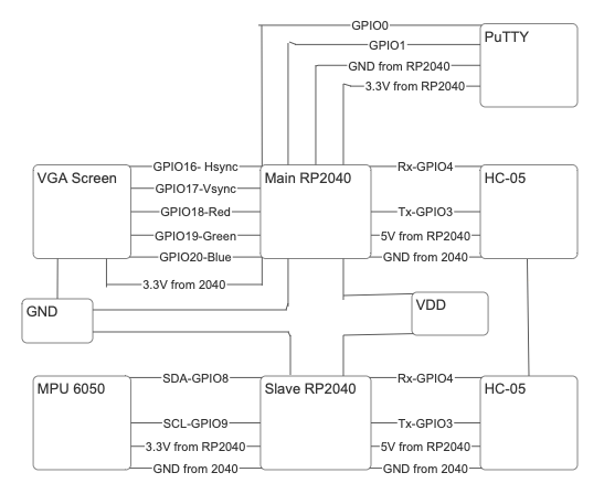
Figure 6 illustrates the circuitry implementation for our project. The core of our setup was the Raspberry Pi Pico Development Board, which is built around the RP2040 microcontroller. We began by establishing the connection between the slave RP2040 to a breadboard, which also acted like our controller. After that, a HC-05 module(transmitter) was connected to this RP2040. The main RP2040 was then connected to a separate breadboard which connected to another HC-05 module (receiver). We made sure to test our circuit as we built it, to make sure that each part for itself before building the full circuit.
For the MPU6050 sensor, which provides the raw gyro measurements, we connected GPIO 8 to the sensor's SDA line and GPIO 9 to its SCL line, facilitating I2C communication. The sensor's VCC and GND were connected to the RP2040's 3.3V output and ground. This setup allowed us to gather and scale the sensor data accurately, which was then sent to the main Pico over Bluetooth. We also established a connection with PuTTY by connecting it with UART communication, as shown in the figure.
Then, the VGA display was connected to the RP2040 through a series of GPIO pins and 330-ohm resistors. Specifically, GPIO 16 was wired to the VGA's Hsync pin, GPIO 17 to Vsync, and GPIOs 18, 19, and 20 to the Red, Green, and Blue pins respectively, each through a 330-ohm resistor. These resistors are crucial as they form a voltage divider, reducing the RP2040's 3.3V output to a range suitable for the VGA input, which expects a voltage between 0 and 0.7V. The VGA GND was connected to the RP2040's ground to complete the circuit.
The visual representation on the VGA screen combined with PuTTY was very important for debugging purposes. Nothing would appear on the screen if any of the hardware connections were wrong. As a result, we could see with our own eyes that the connections were incorrect, and we corrected them as necessary. Additionally, PuTTY was used to debug Bluetooth and later on to control the placement of characters which was needed to play the game.
The device was able to successfully move the cursor around the screen by sensing movement in the controller. Although the buttons on the controller were not successfully implemented, it was still possible to send commands to the controller through a serial interface accessed through PuTTY. In the end, a tic tac toe game was able to be played on the VGA screen between two players, each of which used the same controller by taking turns.
The speed of execution for the device was dependent on the speed at which the PICO could access readings from the bluetooth module and subsequently how fast it could process the readings so they could be displayed on the VGA screen. Thus, this meant the speed of execution was hindered by the bluetooth modules used to communicate between Picos. Since the bluetooth modules were only able to work at a 9600 baud rate, this introduced significant lag to both sending and receiving of messages. A 9600 baud rate means a maximum transfer rate of 9600 bits per second. Although it may seem like a lot, a 9600 baud rate is significantly slower than the clock speed at which the Pico runs on. To put it in perspective, let us consider the average message sent from the Pico controller to the Pico main station. Each message was approximately 30 bytes long, since the buffer contained a maximum of 30 characters and most often the entire buffer was used. Doing the dimensional analysis: (30 characters) * (1 byte per character) *(8 bits per byte) = 240 bits per message. Now we can divide the 240 bits per message by the baud rate to get a value of seconds per message, which is 0.025 seconds per message. This can be multiplied by the frequency of the Pico (133MHz), which results in 3,325,000 clock cycles! Generously assuming that each instruction takes about 5 clock cycles, that is about 665,000 instructions that the Pico is able to execute before one message has been either sent to the bluetooth module or is received from the bluetooth module. Since each message transaction requires one “send” and a subsequent “recieve” on the main pico, this number can be doubled. Thus, it takes around 1,330,000 instructions from the start of sending a message to completely reading the message on the other end. This issue is further compounded by the fact that the reading from and writing to the UART port blocks execution from other threads on the same core. This lag was most evidently seen by the speed of the cursor as it moved around the screen. In general the cursor was not as responsive as the group had hoped.
The cursor location extrapolated from the controller movement was not super accurate, although the movements made on the controller side were seen. The main issue with accuracy came from only using gyroscopic measurements to determine the movement of the player and thus where the cursor should be placed. No measurements were taken from the accelerometer. This results in slight drifting of the cursor as the gyroscope measures slight “ghost” movement. This required the group to calibrate the cursor by placing it in the center of the screen. This needed to be done on a somewhat regular basis as the drifting was somewhat consistent. No drifting was seen in the x direction when moving the cursor, only in the y direction.
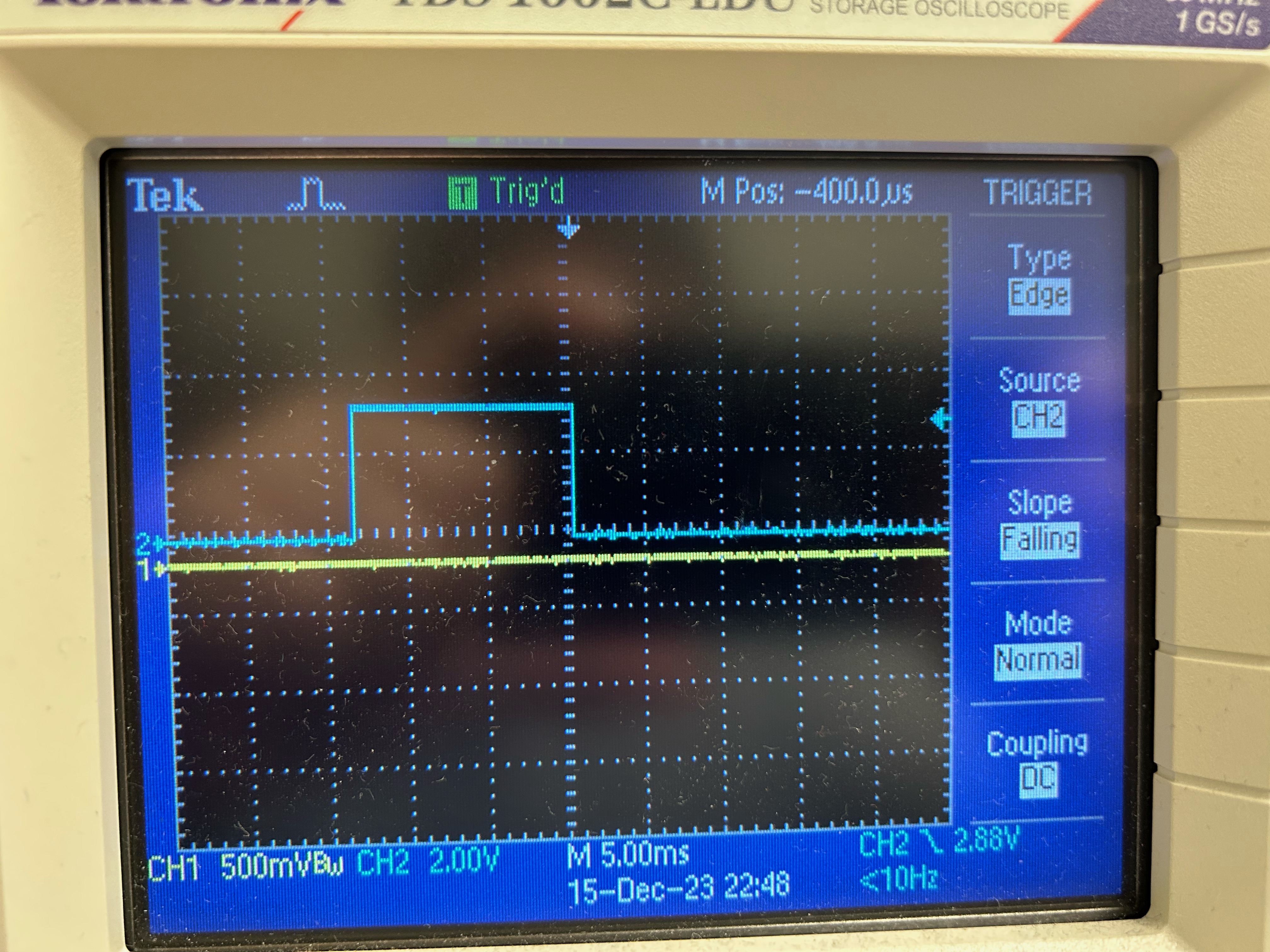
The following is a scope trace of the refresh rate of the VGA monitor.
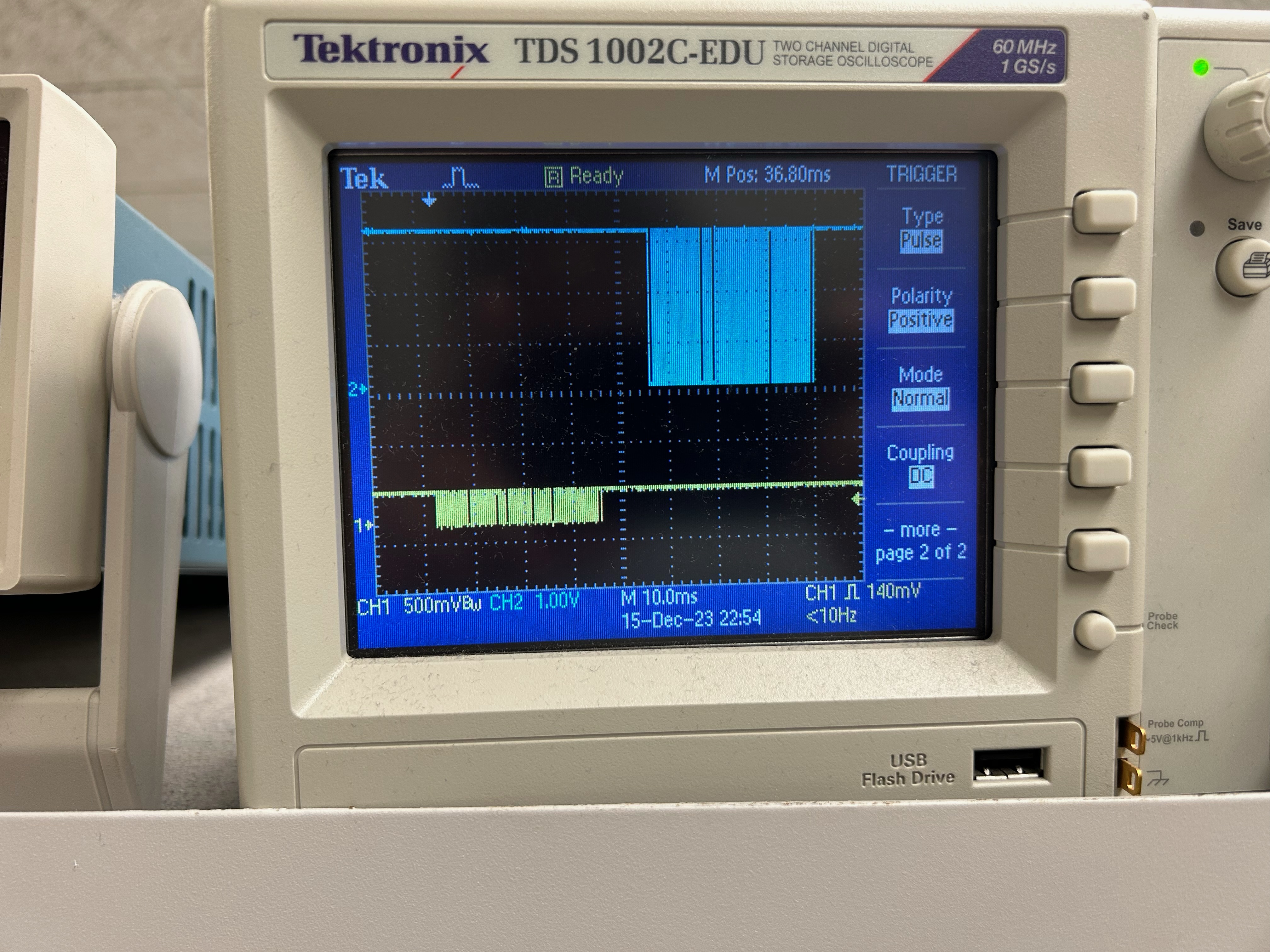
Each message takes about 40ms to fully send. However, as seen in the picture, the message lengths are identical but happens at a separate time. This shows how the message takes time to reach the master device after being sent by the slave. As seen in the figure, it takes around 10ms for the bluetooth module to start sending data over to the master.
The design was not inherently dangerous, and thus no safety measures were put in place for the device. However, if the design were ever to be mass produced, simple safety measures would need to be taken. One example of this would be straps for the controller so it stays connected to your wrist, similar to how the Nintendo Wii Controllers have a strap. This is necessary in case a user moves the controller wildly and the controller slips out of their hand. Another important safety precaution would be having players stand sufficiently far away from each other when playing the game. Although the game is just tic tac toe, so no wild arm movements are expected, it would still be good practice to have players stand somewhat apart from each other so any unexpected movements do not hurt the other players!
The overall usability of the device is somewhat low, and more updates and iterations would be needed to get the device to be one hundred percent user friendly from a commercial standpoint. This is because there still exists some hiccups in the design that would need to be ironed out. One example, as discussed before, is the speed of communication between the Picos. A faster communication protocol between the Pico and the bluetooth module would allow faster communication between each Pico. Another kink that would need to be ironed out is the lack of buttons on the controller, which significantly hinders a users ability to play the game. Overall however, we believe the design needs slight modifications to be made fully user friendly.
The tic-tac-toe game, leveraging the MPU6050 sensor, RP2040 microcontroller and Bluetooth, largely met our expectations. The project successfully translated physical motions into digital commands, allowing for a successful interactive and engaging gaming experience. However, the precision and responsiveness were not always consistent, which could be attributed to the noise in sensor readings and the challenges of wireless communication. In future iterations, we would explore advanced filtering techniques or alternative communication protocols to enhance stability and accuracy. Bluetooth communication did also take a long time to get working properly, which hindered some additional planned features of the project. However, this project taught us the details of integrating hardware and software to create a seamless user interface.
Our design adhered to the relevant standards for electronic devices and communication protocols. The I2C standard facilitated reliable data transfer between the MPU6050 sensor and the microcontroller, and the use of UART for serial communication with Putty was in line with industry practices. The adherence to these standards ensured interoperability and the potential for scalability in our design.
Some components of our codebase were adaptations of publicly available algorithms or algorithms given to us in this course, particularly those related to signal processing from the MPU6050. We did not use any of Altera's IP cores since our project was based on the Raspberry Pi Pico platform.
Throughout the project, we were mindful of intellectual property rights and made efforts to ensure compliance. We utilized some open-source libraries that were available in the public domain, which significantly accelerated the development process. While we took inspiration from existing concepts such as the Wii gaming console, we were careful not to infringe on any patents or trademarks by developing our unique implementation.
Although our project was inspired by commercial motion-controlled gaming systems, we did not engage in reverse-engineering. We developed our algorithms and circuit designs from first principles and documented our design process to maintain transparency.
In conclusion, this project was a valuable learning experience that highlighted the importance of the effective integration of hardware and software. We furthered our knowledge regarding testing and iterative design to refine our project, and the experience has equipped us with a stronger foundation for the future in the field of embedded systems and interactive design.
The group approves this report for inclusion on the course website.
The group approves the video for inclusion on the course youtube channel.
Here is our code in html format so it can be displayed on the website:
Main Station Code
Controller Code
| Hardware Component | Price | Number | Purpose |
|---|---|---|---|
| RP2040 Microcontroller | $6 | 2 | One Pico for the Controller, as well as one main Pico that controls the VGA display, general game logic, and managing communication protocols. |
| VGA Screen | ~$70 | 1 | Display Menu and Tic Tac Toe Board. |
| Breadboards | 2 | Base for mounting and interconnecting all hardware components, including power and ground. One acts as the controller. | |
| Putty Interface | 1 | Enables UART communication with the RP2040, allowing for user input. | |
| MPU6050 IMU | ~$12 | 1 | Gather positional data for the controller. |
| HC-05 Bluetooth Adapter | $10.69 | 2 | Bluetooth adapter to facilitate communication between Picos. |