Demonstration Video
Project Introduction
The project aims to bring the popular mobile game "Piano Tiles 2" to life through a physical hardware version, enhancing the gaming experience and challenging users' hand-eye coordination and reflexes. This interactive adaptation will use a VGA screen to display descending tiles, which players will intercept using flex sensors attached to their fingers. The game's difficulty escalates with the player's score, offering a progressively challenging and engaging experience. This innovative approach not only aims to recreate the digital game in a physical format but also seeks to make it accessible and enjoyable for a broad audience.
High Level Design
"Piano Tiles," a single-player mobile game, was developed by Hu Wen Zeng at Umoni Studio and released on March 28, 2014.[1] Our project aims to reimagine this game using flex sensors, enabling users to experience the touchscreen control aspect of the game without an actual touchscreen, thus offering a novel gaming experience. In the game, tiles cascade down the screen, and players must flex their fingers at precise moments to match the tiles' arrival at the screen's bottom. The game features four tiles, requiring coordination of four fingers. Successful hits are rewarded with distinctive sounds, while misses result in an alternate sound, signaling game over and prompting a restart. Players earn a point for each successful hit, and every ten points, the tile colors shift, adding visual variety to the gameplay.
The sound generation part of the design was accomplished utilizing the implementations of the swooping/chirping birdsong sounds created using DDS (Direct digital synthesis) code from lab 1.
The Direct Digital Synthesis (DDS) algorithm is based on the concept that a variable overflowing is equivalent to one rotation of a phasor. This method involves projecting a rotating phasor onto an axis to generate a sine wave. In DDS, an accumulator represents the phasor's angle, and overflowing this accumulator signifies a full phasor rotation. The algorithm operates by incrementing the accumulator with each audio sample, determining the sine wave's frequency. The frequency output depends linearly on the accumulator's increment value. The precision of this synthesis method can vary based on the accumulator's size, influencing the harmonic distortion in the generated tones. DDS can be utilized in various applications beyond sound synthesis, demonstrating its versatility.[2]
The mathematical synthesis of birdsong, specifically the swoop and chirp sounds, involves using Direct Digital Synthesis (DDS) to accurately generate audio frequencies. The swoop sound is created using a sine wave formula, where the frequency changes over time according to a sinusoidal pattern. The chirp sound, on the other hand, is modeled using a quadratic equation to represent its rapid frequency shift from low to high. [3]
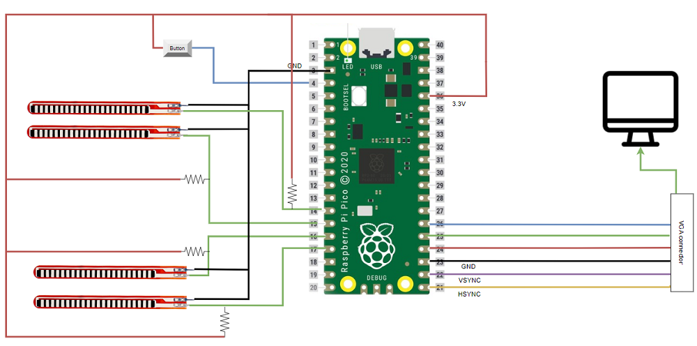
Figure 1. High-level Block Diagram of the design set-up
The comprehensive hardware architecture of the design is illustrated in Figure 1, with detailed coverage of the audio setup (DAC) circuit in subsequent sections. The system configuration comprises four flex sensors linked to a Raspberry Pi through resistors. For game control, a button connected to the RP2040 facilitates game restarts following a game-over scenario. Notably, the flex sensors were meticulously wired with a specific resistor calibration. In our specific design, each sensor necessitated a distinct resistance level, typically falling within the range of 20k ohms to 25k ohms.
Software Design
Given the project's significant reliance on visual elements, the software aspect of the application played a crucial role and encompassed several pivotal blocks. Let's delve into each of these code blocks individually.
-
main():
The main function launches the animation threads and initializes peripherals like the video graphics adapter and the GPIO pins for sensor inputs. As the program's starting point, it coordinates the initialization almost all the communication channels being used, Interrupt Service routines (ISR) and thread (proto thread).
-
Controlling the visual elements:
The visualisation part of the software was built around Protothreads, enabling concurrent operations for better performance. In the process of plotting on the VGA screen, the primary objective of the visual control code is to effectively orchestrate the dynamic movement and interaction of colored tiles within the game environment. Each distinct color, namely cyan, yellow, green, and blue, corresponds to a specific lane, signifying a unique tile type. The variables utilized in this code block are intuitively named, facilitating clarity in their respective roles. The core logic of the code involves assessing the positions of these tiles by considering their indices and incorporating a speed factor denoted as speed_fact.
As the execution progresses, the code continually monitors the indices of the tiles, and upon surpassing a predefined threshold, initiates a sequence of actions. These actions encompass critical game dynamics, including the resetting of indices, score updates, alteration of the color scheme in designated regions of the screen, and the management of game-over scenarios. Crucially, the code's response mechanisms are intricately linked to the state of the flex sensors, introducing a layer of interactivity based on user input.
-
Producing sound:
This code for producing sound operates within an Interrupt Service Routine (ISR) callback, generating sound through a Digital-to-Analog Converter (DAC). Upon GPIO activation (gpio_put(ISR, 1)), the code calculates the sine wave's frequency based on a dynamic amplitude (current_amplitude_0) and phase increment (phase_incr_main_3). The phase accumulator (phase_accum_main_0) is updated, and the sine wave is sampled to produce the DAC output (DAC_output_0).
The amplitude undergoes dynamic adjustment during the sound generation process. It ramps up during the attack phase (count_0 < ATTACK_TIME) and ramps down during the decay phase (count_0 > BEEP_DURATION - DECAY_TIME). The resulting DAC output is masked with control bits and sent through SPI communication. The counter (count_0) is incremented, and the state transitions when the sound duration (BEEP_DURATION) is reached. Upon completion, the ISR callback is reset (gpio_put(ISR, 0)), signaling the end of the sound generation.
-
Fixed point Macros:
The code uses fixed-point arithmetic for efficient numerical calculations. The macros provided help in performing fixed-point operations and for interconversion between fix, float, and integers as per requirement.
The preceding explanation provides an overview of the intricate logic governing crucial segments of the code, addressing challenging aspects of the implementation. Additionally, the code seamlessly integrates functionalities for buttons and flex sensors by straightforwardly reading GPIO pins. For a detailed reference to the entire project code, including comprehensive comments, please refer to Appendix 4 located at the end of the webpage.
A valuable resource that significantly contributed to our project was a publicly available GitHub repository. We found substantial assistance and incorporated certain code snippets from the repository at Ruturajn/ese5190-falling-tiles[4]
.Hardware Design
Key hardware components of the project are follows
- 3D printed flex sensor ring: To ensure the accurate placement of flex sensors on the fingers for optimal performance, we opted to utilize 3D printing technology for crafting a dedicated ring. This 3D printed flex sensor ring serves a dual function by securely enclosing the flex sensors in the precise finger location and providing a comfortable fit for users during gameplay. The design of the ring draws inspiration from an open-source model available on the internet[5], contributing to the project's accessibility and adaptability.
- Integration of Flex Sensors: Incorporating four flex sensors aligned with each lane on the game's visual side, we encountered the challenge of having more sensors than available ADCs on the RP2040 board, prompting a choice between using a multiplexer (MUX) or reducing lanes to three. Despite an attempt to integrate a MUX for increased input capacity, it fell short of providing the required resolution. Consequently, we opted for a digital pin approach, where a pin would register as HIGH if the voltage exceeded approximately 1.8V (approximate value calculated by experimentation), indicating a bent finger. To ensure the accuracy of this threshold, we designed and calibrated a circuit that included carefully selected resistance values (can be seen in circuit in the high level design section). This circuit guaranteed that the threshold aligned precisely with the desired degree of flex detected by the flex sensor, ensuring reliable and responsive gameplay.
- Setup for integration of Audio: For efficient communication with the digital-to-analog converter (DAC), we opted for SPI communication, establishing a streamlined connection to the Raspberry Pi Pico. The DAC, an external chip to the Pi Pico, facilitated the conversion of voltage signals. The DAC's two audio outputs were then directed to a single audio jack which was connected to a speaker, allowing the production of sound.
- VGA setup: The VGA screen connection requires careful attention, as outlined in the provided corresponding table. This detail ensures proper setup and understanding of the full functionality of the VGA interface in the project.
- Button (pulled down): The button served the purpose of restarting the game in the event of its conclusion, providing users with the option to initiate a new gameplay session.
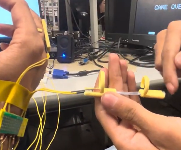
Figure 2. Image of the case for flex-sensor
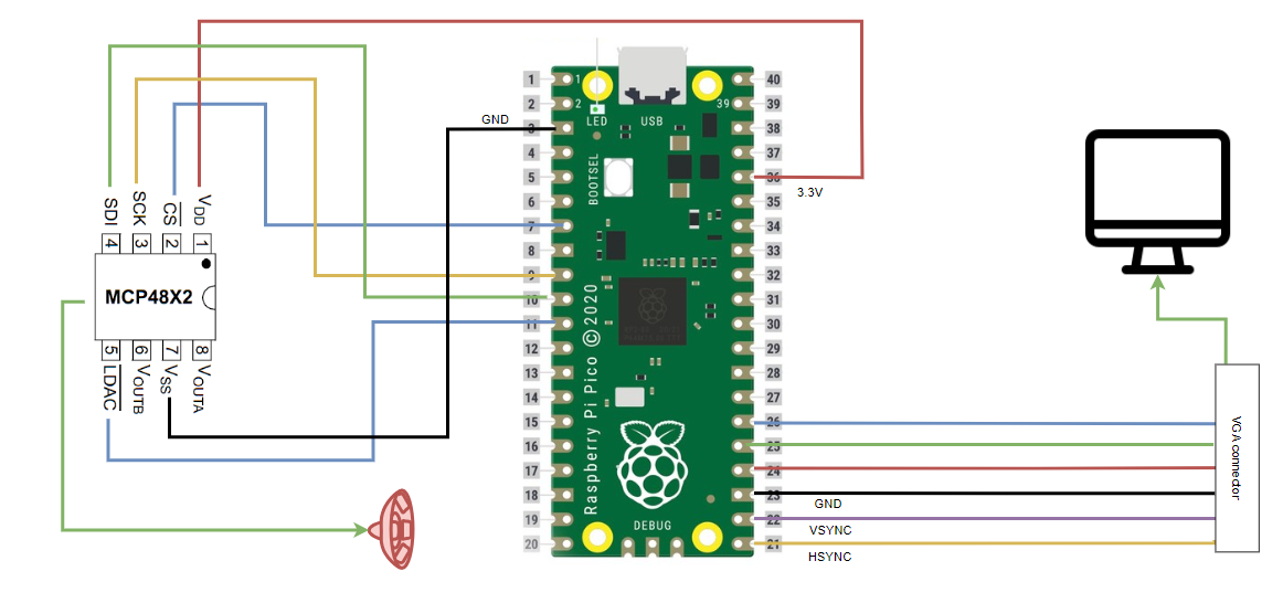
Figure 3. Circuit setup for audio output
| VGA Connector Name | GPIO # | Purpose |
|---|---|---|
| HSYNC | 16 | HSYNC is one of the two digital synchronization pins required to drive a VGA screen. Its primary function is to signal the VGA display when to move to a new row of pixels. The HSYNC signal remains active (logic level high) for 640 pixel clock cycles, which corresponds to one row of the VGA display. |
| VSYNC | 17 | VSYNC is the second of the two digital synchronization pins used for VGA displays. Its main role is to indicate to the VGA screen when to start a new frame. The VSYNC signal remains active (logic level high) for 480 lines (rows of pixels). After these 480 lines, the VSYNC signal goes through a sequence of changes, including a front porch, sync pulse, and back porch, before returning to the start of its active mode for the next frame. |
| Red, Green, Blue | 18,19,20 | These pins are responsible for conveying color information on the VGA display. During each of the 640 clock cycles of the HSYNC active mode, the levels on the RGB lines vary between 0 and 0.7 V. The intensity of the RGB beams will vary to that specific color for a particular pixel. The combination of the intensities on these three pins determines the final color of each pixel on the VGA screen. |
| Ground | RPi 20-40 GND | Serves as a common reference point for all electrical signals such that all components have the same voltage reference point. |
Results
The implementation of a piano tiles variant using flex sensors proved successful in our project. Despite the absence of direct test data, system functionality was effectively verified through the VGA display. The DDS component of the project leveraged code from lab 1.
The system exhibited satisfactory speed of execution on a single core of the RP2040, with no noticeable flickering or lag during gameplay. However, accuracy challenges surfaced with the flex sensors, limiting the system's ability to detect only one flex at a time. This limitation led to potential gameplay issues if a sensor malfunctioned.
Notably, the design presents no safety hazards, and user interaction involves limited motion. Nevertheless, the 3D printed finger-wear may pose usability constraints for individuals with finger sizes outside the design parameters.
Additional Insights:
- The current implementation utilizes a single core of the RP2040. In anticipation of future feature additions, the option to leverage the second core is available to address potential lag or flickering issues, ensuring a smoother user experience.
- The highest recorded high score achieved during testing was 52, with multiple turns reaching approximately 40. This performance metric provides a baseline for evaluating the effectiveness of the system during gameplay.
- An important observation is that once the resistance values for the flex sensors are experimentally determined, they remain constant. This implies that calibration is a one-time process, reducing the need for frequent adjustments and ensuring stable sensor performance over time.
A small gameplay video:
Conclusion
The project met our expectations in reimplementing the "Piano Tiles" game. Future iterations would benefit from spare flex sensors, as one malfunctioning sensor caused significant bugs. To our knowledge, no intellectual property rights were infringed upon during the project. The basic format of the "Piano Tiles" game, being a common element in rhythm and music games, does not constitute exclusive intellectual property. Our code was primarily developed in lab sessions, supplemented by demo codes from the course.
Appendix A
The group approves this report for inclusion on the course website.
The group approves the video for inclusion on the course youtube channel.
The group approves the use of the Gameplay video on the course website, cource youtube channel or any other platforms.
Appendix B: References
- “Piano Tiles.” Wikipedia, Wikimedia Foundation, 18 Nov. 2023, en.wikipedia.org/wiki/Piano_Tiles.
- Adams, Hunter. “DDS.” Vanhunteradams.com, vanhunteradams.com/DDS/DDS.html.
- “Birdsong_synthesis(lab 1).” Vanhunteradams.com, vanhunteradams.com/Pico/Birds/Birdsong_synthesis.html.
- “Falling Tiles.” github.com, github.com/Ruturajn/ese5190-falling-tiles.
- “3D ring design.” thingiverse.com, www.thingiverse.com/thing:1606915.
- “VGA Connector Pinout - Basic Introduction Is Here.” www.nextpcb.com, www.nextpcb.com/blog/vga-connector-pinout.
- “Flex Sensor.” adafruit.com, www.adafruit.com/product/1070.
Appendix C: List of roles
Wooyoung Cho : Website Development
Siddhant Ahlawat: Software Development
Rahul Goel: Hardware Development
Appendix D: Code
/**
 * Hunter Adams (vha3@cornell.edu)
 *
 * Mandelbrot set calculation and visualization
 * Uses PIO-assembly VGA driver.
 *
 *
 * https://vanhunteradams.com/FixedPoint/FixedPoint.html
 * https://vanhunteradams.com/Pico/VGA/VGA.html
 *
 * HARDWARE CONNECTIONS
 *  - GPIO 16 ---> VGA Hsync
 *  - GPIO 17 ---> VGA Vsync
 *  - GPIO 18 ---> 330 ohm resistor ---> VGA Red
 *  - GPIO 19 ---> 330 ohm resistor ---> VGA Green
 *  - GPIO 20 ---> 330 ohm resistor ---> VGA Blue
 *  - RP2040 GND ---> VGA GND
 *  - GPIO 15-A mux
 *  - GPIO 14-B mux
 * GPIO 13-C mux
 * gpio26/ADC0- comout mux
 *1
 *
 * RESOURCES USED
 *  - PIO state machines 0, 1, and 2 on PIO instance 0
 *  - DMA channels 0 and 1
 *  - 153.6 kBytes of RAM (for pixel color data)
 *
 */
#include "vga_graphics.h"
#include
#include
#include "pico/stdlib.h"
#include "pico/multicore.h"
#include "hardware/pio.h"
#include "hardware/dma.h"
#include "hardware/adc.h"
#include "registers.h"
#include "math.h"
#include "hardware/spi.h"
#include "hardware/sync.h"
// Include protothreads
#include "pt_cornell_rp2040_v1.h"
////////////////////////////////////////////////////////////////////////////////////////////////////
/////////////// Stuff for Mandelbrot ///////////////////////////////////////////////////////////////
////////////////////////////////////////////////////////////////////////////////////////////////////
// Fixed point data type
typedef signed int fix28 ;
#define multfix28(a,b) ((fix28)(((( signed long long)(a))*(( signed long long)(b)))>>28))
#define float2fix28(a) ((fix28)((a)*268435456.0f)) // 2^28
#define fix2float28(a) ((float)(a)/268435456.0f)
#define int2fix28(a) ((a)<<28)
// the fixed point value 4
#define FOURfix28 0x40000000
#define SIXTEENTHfix28 0x01000000
#define ONEfix28 0x10000000
int previous_sound=0;
// Maximum number of iterations
#define max_count 1000
int input_flex1=0;
int input_flex2=0;
int input_flex3=0;
int input_flex4=0;
#define LEFT_VERT 150
#define MID_VERT 240
#define RIGHT_VERT 420
#define THIRD_VERT 330
float speed_fact=3;
#define LEFT_VERT_TILES 160
#define MID_VERT_TILES 250
#define THIRD_VERT_TILES 340
#define RIGHT_VERT_TILES 430
#define SELECT_LINE_A 10
#define SELECT_LINE_B 11
#define SELECT_LINE_C 12
#define SELECT_LINE_D 13
#define RESTART_PIN 4
#define RESTART_PIN_REG ((volatile uint32_t *)(IO_BANK0_BASE + 0x010))
uint adc_x_raw;
int level=2;
//***************************************************************************************
// fixed point macros
typedef signed int fix15 ;
#define multfix15(a,b) ((fix15)((((signed long long)(a))*((signed long long)(b)))>>15))
#define float2fix15(a) ((fix15)((a)*32768.0))
#define fix2float15(a) ((float)(a)/32768.0)
#define absfix15(a) abs(a)
#define int2fix15(a) ((fix15)(a << 15))
#define fix2int15(a) ((int)(a >> 15))
#define char2fix15(a) (fix15)(((fix15)(a)) << 15)
#define divfix(a,b) (fix15)( (((signed long long)(a)) << 15) / (b))

//Direct Digital Synthesis (DDS) parameters
#define two32 4294967296.0  // 2^32 (a constant)
#define Fs 40000            // sample rate

// the DDS units - core 0
// Phase accumulator and phase increment. Increment sets output frequency.
volatile unsigned int phase_accum_main_0;
volatile unsigned int phase_incr_main_0 = (400.0*two32)/Fs ;

// DDS sine table (populated in main())
#define sine_table_size 256
fix15 sin_table[sine_table_size] ;

// Values output to DAC
int DAC_output_0 ;
int DAC_output_1 ;

// Amplitude modulation parameters and variables
fix15 max_amplitude = int2fix15(1) ;    // maximum amplitude
fix15 attack_inc ;                      // rate at which sound ramps up
fix15 decay_inc ;                       // rate at which sound ramps down
fix15 current_amplitude_0 = 0 ;         // current amplitude (modified in ISR)
fix15 current_amplitude_1 = 0 ;         // current amplitude (modified in ISR)

// Timing parameters for beeps (units of interrupts)
#define ATTACK_TIME             200
#define DECAY_TIME              200
#define SUSTAIN_TIME            10000
#define BEEP_DURATION           5200
#define BEEP_REPEAT_INTERVAL    40000

 int color_of_tiles=2;
// State machine variables
volatile unsigned int STATE_0 = 0 ;
volatile unsigned int count_0 = 0 ;

// SPI data
uint16_t DAC_data_1 ; // output value
uint16_t DAC_data_0 ; // output value

// DAC parameters (see the DAC datasheet)
// A-channel, 1x, active
#define DAC_config_chan_A 0b0011000000000000
// B-channel, 1x, active
#define DAC_config_chan_B 0b1011000000000000

//SPI configurations (note these represent GPIO number, NOT pin number)
#define PIN_MISO 4
#define PIN_CS   5
#define PIN_SCK  6
#define PIN_MOSI 7
#define LDAC     8
#define LED      25
#define ISR      15
#define SPI_PORT spi0

// Two variables to store core number
volatile int corenum_0  ;

// Global counter for spinlock experimenting
volatile int global_counter = 0 ;
//***********
int flag=0;
//**********************************
//***********************************************************sound

// This timer ISR is called on core 0
bool repeating_timer_callback_core_0(struct repeating_timer *t) {
    if (STATE_0 == 1) {
        // DDS phase and sine table lookup
        gpio_put(ISR, 1) ;
        float y;
        y=-260*sin(-1*3.141592*count_0/5200)+1740;
        volatile unsigned int phase_incr_main_3=y*(two32)/Fs;
        phase_accum_main_0 += phase_incr_main_3  ;
        DAC_output_0 = fix2int15(multfix15(current_amplitude_0,
            sin_table[phase_accum_main_0>>24])) + 2048 ;

        // Ramp up amplitude
        if (count_0 < ATTACK_TIME) {
            current_amplitude_0 = (current_amplitude_0 + attack_inc) ;
        }
        // Ramp down amplitude
        else if (count_0 > BEEP_DURATION - DECAY_TIME) {
            current_amplitude_0 = (current_amplitude_0 - decay_inc) ;
        }

        // Mask with DAC control bits
        DAC_data_0 = (DAC_config_chan_B | (DAC_output_0 & 0xffff))  ;

        // SPI write (no spinlock b/c of SPI buffer)
        spi_write16_blocking(SPI_PORT, &DAC_data_0, 1) ;

        // Increment the counter
        count_0 += 1 ;

        // State transition?
        if (count_0 == BEEP_DURATION) {
            STATE_0 = 0 ;
            count_0 = 0 ;
            flag=0;
        }
        gpio_put(ISR, 0) ;
    }
    else if (STATE_0 ==2)
       {
        // DDS phase and sine table lookup
        gpio_put(ISR, 1) ;
        float y;
        y=0.000184*count_0*count_0 + 2000;
        volatile unsigned int phase_incr_main_2 = (y*two32)/Fs ;
        phase_accum_main_0 += phase_incr_main_2  ;
        DAC_output_0 = fix2int15(multfix15(current_amplitude_0,
            sin_table[phase_accum_main_0>>24])) + 2048 ;

        // Ramp up amplitude
        if (count_0 < ATTACK_TIME) {
            current_amplitude_0 = (current_amplitude_0 + attack_inc) ;
        }
        // Ramp down amplitude
        else if (count_0 > BEEP_DURATION - DECAY_TIME) {
            current_amplitude_0 = (current_amplitude_0 - decay_inc) ;
        }

        // Mask with DAC control bits
        DAC_data_0 = (DAC_config_chan_B | (DAC_output_0 & 0xffff))  ;

        // SPI write (no spinlock b/c of SPI buffer)
        spi_write16_blocking(SPI_PORT, &DAC_data_0, 1) ;

        // Increment the counter
        count_0 += 1 ;

        // State transition?
        if (count_0 == BEEP_DURATION) {
            STATE_0 = 0 ;
            count_0 = 0 ;
            flag=0;
        }
        gpio_put(ISR, 0) ;
    }
    // State transition?
    else {
        count_0 += 1 ;
        if (flag==1) {
            current_amplitude_0 = 0 ;
            STATE_0 = 1 ;
            count_0 = 0 ;
            flag=0;
        }
        if (flag==2) {
            current_amplitude_0 = 0 ;
            STATE_0 = 2 ;
            count_0 = 0 ;
            flag=0;
        }
    }

    // retrieve core number of execution
    corenum_0 = get_core_num() ;

    return true;
}

//**************************************************

uint act_adc() {
    adc_select_input(0);
    adc_x_raw = adc_read();
    uint adc_x = 0;
    input_flex1=0;
    input_flex2=0;
    input_flex3=0;
    input_flex4=0;
    input_flex1=gpio_get(SELECT_LINE_A);
    input_flex2=gpio_get(SELECT_LINE_B);
    input_flex3=gpio_get(SELECT_LINE_C);
    input_flex4=gpio_get(SELECT_LINE_D);
//*********************************
 if (input_flex2 == 1 ){
      adc_x=2;
        fillRect(MID_VERT,460,60,20,WHITE);
        fillRect(LEFT_VERT,460,60,20,0);
        fillRect(THIRD_VERT,460,60,20,0);
        fillRect(RIGHT_VERT,460,60,20,0);
    }
    else if (input_flex4== 1 ) {
        adc_x=4;
        fillRect(RIGHT_VERT,460,60,20,WHITE);
        fillRect(LEFT_VERT,460,60,20,0);
        fillRect(THIRD_VERT,460,60,20,0);
        fillRect(MID_VERT,460,60,20,0);
    }else if (input_flex1==1 ) {
        adc_x=1;
        fillRect(LEFT_VERT,460,60,20,WHITE);
        fillRect(MID_VERT,460,60,20,0);
        fillRect(THIRD_VERT,460,60,20,0);
        fillRect(RIGHT_VERT,460,60,20,0);
    }
    else if (input_flex3==1 ) {
        adc_x=3;
        fillRect(THIRD_VERT,460,60,20,WHITE);
        fillRect(LEFT_VERT,460,60,20,0);
        fillRect(MID_VERT,460,60,20,0);
        fillRect(RIGHT_VERT,460,60,20,0);
    }
    else if(adc_x==0)
    {fillRect(THIRD_VERT,460,60,20,0);
        fillRect(LEFT_VERT,460,60,20,0);
        fillRect(MID_VERT,460,60,20,0);
        fillRect(RIGHT_VERT,460,60,20,0);

    }

    sleep_ms(10);
    return adc_x;
}

void draw_fill_rect(short x, short y, short w, short h, char color, short inc_dec){
    fillRect(x,y,w,h,color);
    fillRect(x,y,w,inc_dec,0);
    fillRect(x,y+h,w,inc_dec,color);
    sleep_ms(10);
}

void update_score(uint score){
    fillRect(30,60,240,20,0);
    /* setCursor(30, 30); */
    /* setTextSize(3); */
    char str_score[3] = {'0', '0', '0'};
    str_score[2] = (score % 10) + '0';
    str_score[1] = ((score/10) % 10) + '0';
    str_score[0] = (((score/10)/10) % 10) + '0';
    drawChar(30, 60, str_score[0], WHITE, 0, 2);
    drawChar(45, 60, str_score[1], WHITE, 0, 2);
    drawChar(60, 60, str_score[2], WHITE, 0, 2);
}


// This thread runs on core 0
static PT_THREAD (protothread_core_0(struct pt *pt))
{
    // Indicate thread beginning
    PT_BEGIN(pt) ;


     uint blue_indx = 20, green_indx = 40, cyan_indx = 60, yellow_indx=0, joystick_pos = 0;
    uint curr_score = 0, buttons_status = 0;

    drawChar(30, 30, 'S', WHITE, 0, 2);
    drawChar(45, 30, 'c', WHITE, 0, 2);
    drawChar(60, 30, 'o', WHITE, 0, 2);
    drawChar(75, 30, 'r', WHITE, 0, 2);
    drawChar(90, 30, 'e', WHITE, 0, 2);
    drawChar(105, 30, ':', WHITE, 0, 2);
    update_score(curr_score);

    sleep_ms(5000);

    while(true) {
        while (true){
            joystick_pos = act_adc();
            char info[100];
      sprintf(info, "LEVEL:%d| ", (level-1));
      setCursor(0,0);
      setTextColor2(WHITE, BLACK);
      setTextSize(2);
      writeString(info);

      if(curr_score>10 && curr_score<21)
      {level=3;}
      if(curr_score>20&&curr_score<31)
      {level=4;}
       if(curr_score>30&&curr_score<41)
      {level=5;}
      if(curr_score>40&&curr_score<51)
      {level=6;}
        if(curr_score>50&&curr_score<61)
      {level=7;}
      if(curr_score>60&&curr_score<71)
      {level=8;}
      if(curr_score>70&&curr_score<81)
      {level=9;}
      if(curr_score>80&&curr_score<91)
      {level=10;}
      //speed_fact=level;

      switch((level-1))
      {
               case 1: color_of_tiles=2;
                    break;
               case 2: color_of_tiles=3;
                     break;
               case 3: color_of_tiles=4;
                     break;
               case 4: color_of_tiles=5;
                       break;
                case 5: color_of_tiles=6;
                       break;
               case 6: color_of_tiles=7;
                        break;
               case 7: color_of_tiles=2;
                        break;
               default: color_of_tiles=7;

      }

            if (cyan_indx > 355/speed_fact) {
                cyan_indx = 0;
                fillRect(RIGHT_VERT_TILES,300,40,160,0);
                if (joystick_pos ==4) {
                    sleep_ms(40);
                    fillRect(RIGHT_VERT_TILES,360,40,100,RED);
                    flag=1;
                    sleep_ms(40);
                    fillRect(RIGHT_VERT_TILES,360,40,100,0);
                    curr_score += 1;
                    update_score(curr_score);
                } else {
                    fillRect(RIGHT_VERT,460,60,20,0);
                    flag=2;
                    break;
                }
            }


            if (yellow_indx > 355/speed_fact) {
                yellow_indx = 0;
                fillRect(THIRD_VERT_TILES,300,40,160,0);
                if (joystick_pos ==3) {
                    sleep_ms(40);
                    fillRect(THIRD_VERT_TILES,360,40,100,RED);
                    flag=1;
                    sleep_ms(40);
                    fillRect(THIRD_VERT_TILES,360,40,100,0);
                    curr_score += 1;
                    update_score(curr_score);
                } else {
                    fillRect(THIRD_VERT,460,60,20,0);
                    flag=2;
                    break;
                }
            }

            if (green_indx > 355/speed_fact) {
                green_indx = 0;
                fillRect(MID_VERT_TILES,300,40,160,0);
                if (joystick_pos == 2) {
                    sleep_ms(40);
                    fillRect(MID_VERT_TILES,360,40,100,RED);
                    flag=1;
                    sleep_ms(40);
                    fillRect(MID_VERT_TILES,360,40,100,0);
                    curr_score += 1;
                    update_score(curr_score);
                } else {
                    fillRect(MID_VERT,360,60,20,0);
                    flag=2;
                    break;
                }
            }

            if (blue_indx > 355/speed_fact) {
                blue_indx = 0;
                fillRect(LEFT_VERT_TILES,300,40,160,0);
                if (joystick_pos==1) {
                    sleep_ms(40);
                    fillRect(LEFT_VERT_TILES,360,40,100,RED);
                    flag=1;
                    sleep_ms(40);
                    fillRect(LEFT_VERT_TILES,360,40,100,0);

                    curr_score += 1;
                    update_score(curr_score);
                } else {
                    fillRect(LEFT_VERT,360,60,20,0);
                    flag=2;
                    break;
                }
            }


            draw_fill_rect(LEFT_VERT_TILES,(blue_indx*speed_fact),40,100,color_of_tiles,speed_fact);
            draw_fill_rect(MID_VERT_TILES,(green_indx*speed_fact),40,100,color_of_tiles,speed_fact);
            draw_fill_rect(RIGHT_VERT_TILES,(cyan_indx*speed_fact),40,100,color_of_tiles,speed_fact);
            draw_fill_rect(THIRD_VERT_TILES,(yellow_indx*speed_fact),40,100,color_of_tiles,speed_fact);
            cyan_indx++;
            green_indx++;
            blue_indx++;
            yellow_indx++;
            //speed_fact= speed_fact+ 0.1;
        }

        fillRect(LEFT_VERT_TILES,(blue_indx*speed_fact),40,100,0);
        fillRect(MID_VERT_TILES,(green_indx*speed_fact),40,100,0);
        fillRect(RIGHT_VERT_TILES,(cyan_indx*speed_fact),40,100,0);
        fillRect(THIRD_VERT_TILES,(yellow_indx*speed_fact),40,100,0);

        drawChar(180, 240, 'G', WHITE, 0, 5);
        drawChar(210, 240, 'A', WHITE, 0, 5);
        drawChar(240, 240, 'M', WHITE, 0, 5);
        drawChar(270, 240, 'E', WHITE, 0, 5);
        drawChar(300, 240, ' ', WHITE, 0, 5);
        drawChar(330, 240, 'O', WHITE, 0, 5);
        drawChar(360, 240, 'V', WHITE, 0, 5);
        drawChar(390, 240, 'E', WHITE, 0, 5);
        drawChar(420, 240, 'R', WHITE, 0, 5);/////////
        drawChar(450, 240, '!', WHITE, 0, 5);
        drawChar(480, 240, '!', WHITE, 0, 5);
        level=2;
        buttons_status = register_read(RESTART_PIN_REG);
        printf("0x%08x\n", buttons_status);
        while (buttons_status == 0){
            buttons_status = register_read(RESTART_PIN_REG);
            printf("0x%08x\n", buttons_status);
            sleep_ms(10);
        }

        fillRect(180,240,400,100,0);
        curr_score = 0;
        update_score(curr_score);

        }
    // Indicate thread end
    PT_END(pt) ;
}

int main() {

    gpio_init(RESTART_PIN);
    gpio_set_dir(RESTART_PIN, GPIO_IN);

     gpio_init(SELECT_LINE_A);
    gpio_set_dir(SELECT_LINE_A, GPIO_IN);

    gpio_init(SELECT_LINE_B);
    gpio_set_dir(SELECT_LINE_B, GPIO_IN);

    gpio_init(SELECT_LINE_C);
    gpio_set_dir(SELECT_LINE_C, GPIO_IN);

    gpio_init(SELECT_LINE_D);
    gpio_set_dir(SELECT_LINE_D, GPIO_IN);
    // Initialize stdio
    stdio_init_all();

    // Initialize VGA
    initVGA() ;

    /* int pattern_array[6] = {20, 80, 20, 120, 60, 20} */

    adc_init();
    // Make sure GPIO is high-impedance, no pullups etc
    adc_gpio_init(26);

//****************************************
 // Initialize SPI channel (channel, baud rate set to 20MHz)
    spi_init(SPI_PORT, 20000000) ;
    // Format (channel, data bits per transfer, polarity, phase, order)
    spi_set_format(SPI_PORT, 16, 0, 0, 0);

    // Map SPI signals to GPIO ports
    gpio_set_function(PIN_MISO, GPIO_FUNC_SPI);
    gpio_set_function(PIN_SCK, GPIO_FUNC_SPI);
    gpio_set_function(PIN_MOSI, GPIO_FUNC_SPI);
    gpio_set_function(PIN_CS, GPIO_FUNC_SPI) ;

    // Map LDAC pin to GPIO port, hold it low (could alternatively tie to GND)
    gpio_init(LDAC) ;
    gpio_set_dir(LDAC, GPIO_OUT) ;
    gpio_put(LDAC, 0) ;

    // Map LED to GPIO port, make it low
    gpio_init(LED) ;
    gpio_set_dir(LED, GPIO_OUT) ;
    gpio_put(LED, 0) ;


    gpio_init(ISR) ;
    gpio_set_dir(ISR, GPIO_OUT) ;
    gpio_put(ISR, 0) ;

// set up increments for calculating bow envelope
    attack_inc = divfix(max_amplitude, int2fix15(ATTACK_TIME)) ;
    decay_inc =  divfix(max_amplitude, int2fix15(DECAY_TIME)) ;

    // Build the sine lookup table
    // scaled to produce values between 0 and 4096 (for 12-bit DAC)
    int ii;
    for (ii = 0; ii < sine_table_size; ii++){
         sin_table[ii] = float2fix15(2047*sin((float)ii*6.283/(float)sine_table_size));
    }

    // Create a repeating timer that calls
    // repeating_timer_callback (defaults core 0)
    struct repeating_timer timer_core_0;

    // Negative delay so means we will call repeating_timer_callback, and call it
    // again 25us (40kHz) later regardless of how long the callback took to execute
    add_repeating_timer_us(-25,
        repeating_timer_callback_core_0, NULL, &timer_core_0);


//*******************************************

        // Add core 0 threads
    pt_add_thread(protothread_core_0) ;
        pt_schedule_start ;

}