Gyroscope-Controlled 2D Labyrinth Game
Designed by
Kailing Shen(ks977), Ziyuan Lin(zl647), Yifan Feng (yf372)
Demonstration Video
Introduction
We propose to create an interactive Labyrinth game controlled via a gyroscope, utilizing two Raspberry Pi Pico microcontrollers to facilitate wireless communication and game display.
In the ever-evolving world of interactive gaming, the integration of simple yet powerful technology can lead to intriguing and enjoyable experiences. Our project embodies this concept by introducing an interactive Labyrinth game, ingeniously controlled through a gyroscope and powered by two Raspberry Pi Pico microcontrollers. This innovative setup transforms traditional gameplay into a modern, immersive experience.
The core of our design revolves around the seamless integration of hardware and wireless communication. One Raspberry Pi PicoW acts as the heart of the controller, interfaced with a gyroscope to detect and interpret the player's movements. This Pico is also equipped with a Wi-Fi module, enabling it to communicate wirelessly. The player's physical tilts and turns are translated into digital signals, creating an intuitive and engaging control mechanism for the game.
The second Raspberry Pi Pico plays a crucial role in visualizing the game. It connects to a VGA display, bringing the Labyrinth to life with vivid graphics and real-time response to the player's actions. Another Wi-Fi module on this PicoW ensures a constant and smooth flow of data between the controller and the display. This wireless connection not only simplifies the setup but also enhances the flexibility and appeal of the game, allowing for a clutter-free environment.
Our project is not just a game; it's a testament to the power of combining classic gaming concepts with modern technology. By leveraging the capabilities of the Raspberry Pi Pico and the intuitive control offered by a gyroscope, we create an engaging and novel gaming experience. This Labyrinth game stands as a prime example of how technology can reinvent and revitalize traditional entertainment forms, making them more accessible and enjoyable in the digital age.
Software Design
Our project's software architecture is intricately designed, divided into two principal modules: the Control and Data Transmission Module, and the Data Reception and Game Logic Module. These modules are engineered to perform distinct, specialized functions that collectively ensure a seamless and interactive gaming experience.
This module is responsible for acquiring angle measurements from the Inertial Measurement Unit (IMU), which includes an accelerometer, and processing two button-press signals. The processed control data are then transmitted through UDP. The module's functionality is achieved through a timer interrupt and a dedicated thread.
- Timer Interrupt for Data Measurements
Activated by the interrupt, the system commences a process to retrieve raw data from the Inertial Measurement Unit (IMU). This data acquisition is a critical step in determining the tilt angles of the plane along both the x and y axes. The procedure involves a crucial computation using the arctangent function (arctan), which effectively translates the raw IMU data into meaningful angular measurements. These angles are then further processed, undergoing a transformation into their corresponding cosine values.
              accel_x = acceleration[0];
              accel_y = acceleration[1];
              accel_z = acceleration[2];
              angle_v_rad = atan2(-accel_x, accel_z) + M_PI/2;
              angle_h_rad = atan2(-accel_y, accel_z) + M_PI/2;
              cos_angle_v = float2fix15(cos(angle_v_rad));
              cos_angle_h = float2fix15(cos(angle_h_rad));
This conversion is an essential step, as it refines the angular data into a format that is more suitable for the subsequent stages of the control logic. The cosine values thus obtained play a pivotal role in the game’s mechanics, directly influencing the movement and interaction of the quad within the virtual maze.
Button press signals are concurrently recorded and, alongside the cosine values, are buffered for transmission. A flag is set to notify the data transmission thread that data is ready for sending.
- UDP Data Send Thread
A dedicated thread handles data transmission using UDP. This approach follows the protocol established in the example project "Symmetric UDP send/receive from PicoW to PIcoW," ensuring efficient and reliable data communication.
This module is tasked with receiving the tilt angle cosine values and button pressing signals, applying these to the game logic to determine the position of the quad within the maze and to make game state decisions, such as win/loss determinations, and displaying the game interface on a VGA screen. It involves a timer interrupt and two threads.
- Timer Interrupt for Game Logic
The timer interrupts serve the game logic. Using the received cosine values of the tilt angles, the module calculates the acceleration of the quad. Applying motion formulas that consider friction, it computes the displacement of the quad, thereby determining its position on the maze plane. This position is then used for collision detection with the maze walls and to assess whether the quad has reached the endpoint or fallen into a trap.
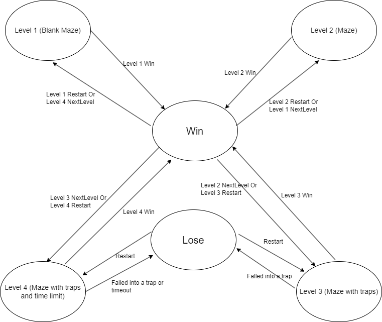
Game Logic
- UDP Data Send Thread
A dedicated thread handles data transmission using UDP. This approach follows the protocol established in the example project "Symmetric UDP send/receive from PicoW to PIcoW," ensuring efficient and reliable data communication.
- VGA Display Thread
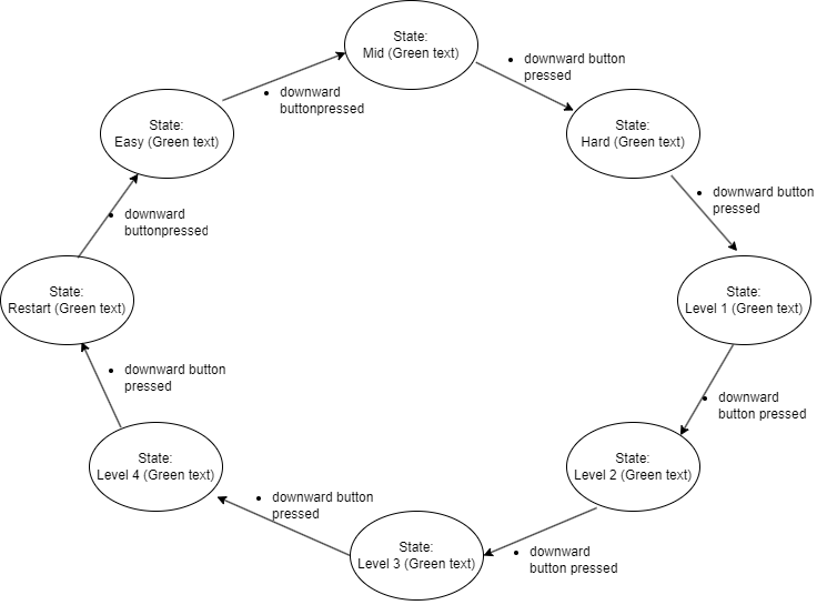
The VGA display thread is split into two parts: displaying setting options (like restart, difficulty levels, and maze levels) and showing the maze plane.
The setting options are controlled by two buttons. One button moves the selection downward, with the selected option highlighted in green. The other button confirms the selection, instantly updating the game settings to the chosen option.
VGA Logic
The maze plane display shows the maze layout and the real-time position of the quad. Due to memory constraints of the PicoW, the maze map is divided into 8x11 blocks, significantly reducing memory requirements. The collision detection in the timer interrupts translates the new position of the quad into its respective block and position within that block. This information is then used for collision detection, only requiring data from a 9x12 2D array that stores the wall information of the maze.
Hardware Design
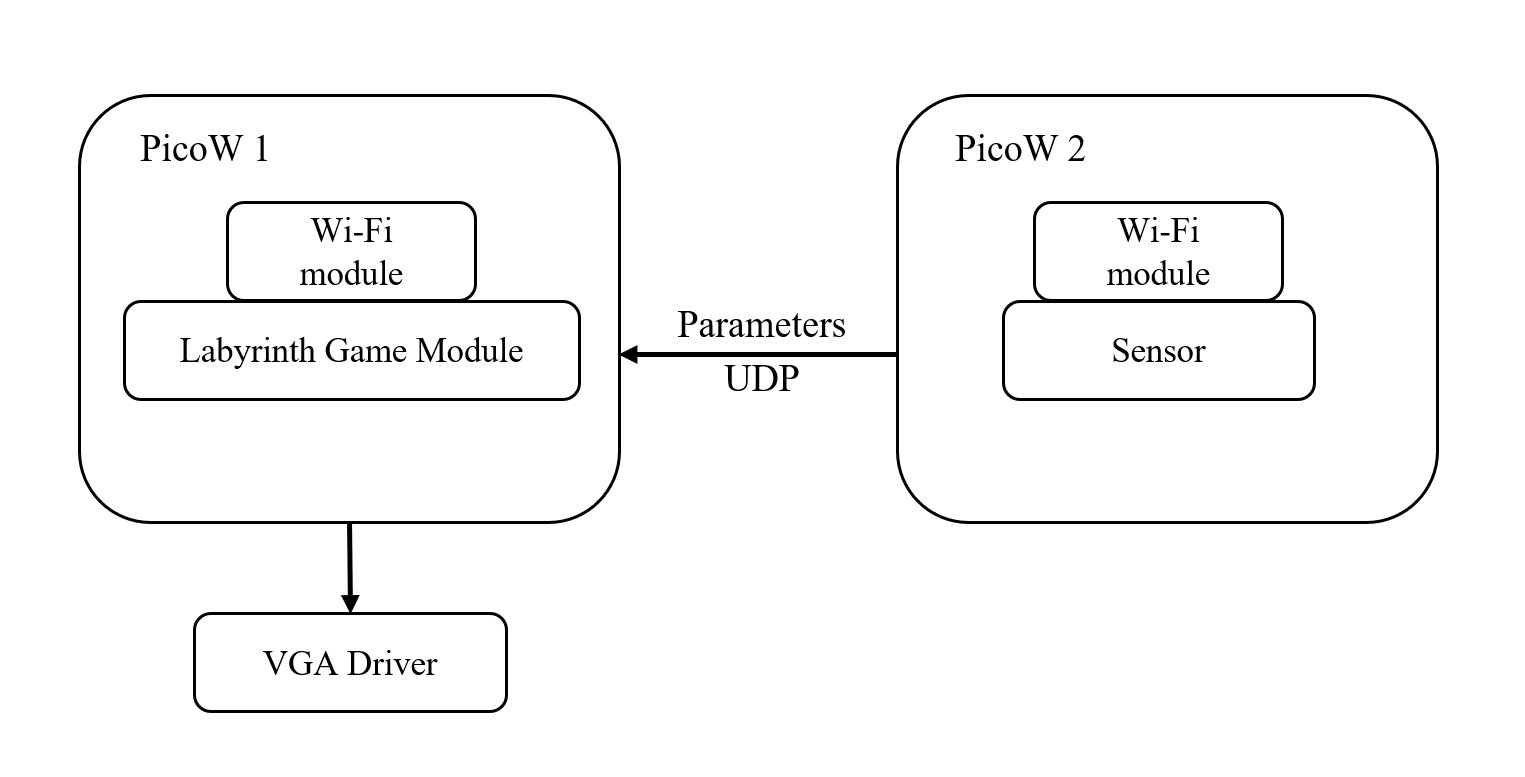
Block Diagram of Top Level Design
According to top level module, we can see that this project is built around two Raspberry Pi Pico W microcontrollers, each serving a specific function in the game setup, and making use of the versatile capabilities of the Pico W platform. Here is the PicoW datasheet to better show illustrate our connectivity.
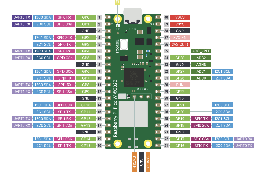
PicoW
The first Raspberry Pi Pico W, referred to as PicoW 1, is dedicated to game visualization and Wi-Fi communication. It plays a pivotal role in displaying the maze on a VGA monitor, creating an immersive visual experience for the player.
The hardware configuration for PicoW 1 includes:
- RP2040 GPIO 2 connected to 3.3V, powering the Wi-Fi module for wireless communication.
- GPIO 16 and 17 are used for VGA Horizontal and Vertical sync signals, respectively, ensuring the monitor displays images correctly.
- GPIOs 18, 19, and 20, each connected through a 330 ohm resistor to the VGA's Red, Green, and Blue inputs, control the color output on the VGA display.
- A connection from RP2040 GND to VGA GND is established for grounding and signal integrity.
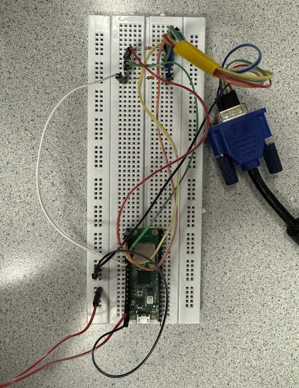
Physical connectivity diagram
The second Raspberry Pi Pico W, named PicoW 2, is engineered for control and input. It interfaces with a gyroscope sensor and buttons, translating physical inputs into game actions.
The hardware setup for PicoW 2 includes:
- GPIOs 8 and 9 connected to the MPU6050 gyroscope sensor's SDA and SCL lines, enabling motion sensing.
- 3.3v and GND connections to the MPU6050 for power and grounding.
- GPIO 15 and 21 connected to two buttons, designed for menu navigation and selection within the game.
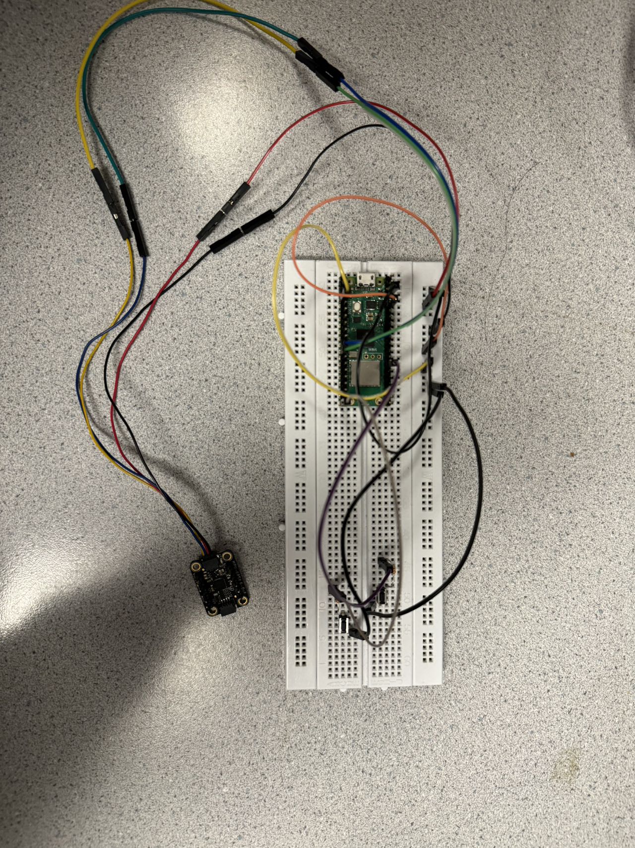
Physical connectivity diagram
This dual-Pico W setup creates a dynamic and responsive gaming system. PicoW 2, with its sensor and buttons, captures player inputs and transmits these parameters via Wi-Fi to PicoW 1. PicoW 1, in turn, processes these inputs to adjust the game's visuals in real-time on the VGA display, offering an engaging and interactive labyrinth navigating experience. This project highlights the potential of Raspberry Pi Pico W microcontrollers in creating sophisticated, yet accessible, gaming and interactive systems.
In our Wi-Fi module, we are implementing this function to send and receive the data we want to process. The protocl we used is UDP, which is a connectionless protocol. UDP uses a simple connectionless communication model with a minimum of protocol mechanisms. UDP provides checksums for data integrity, and port numbers for addressing different functions at the source and destination of the datagram. It has no handshaking dialogues and thus exposes the user's program to any unreliability of the underlying network; there is no guarantee of delivery, ordering, or duplicate protection.
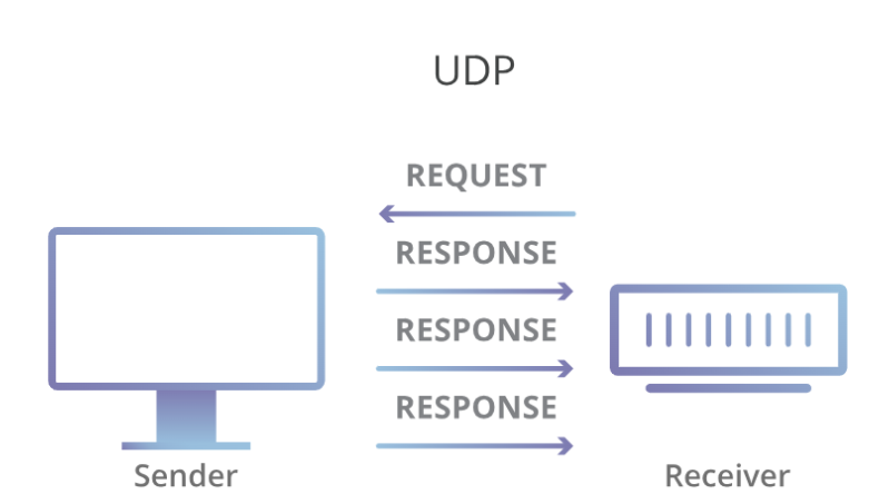
UDP schematic diagram
The Picow has a WIFI module that can be used to connect to the internet, using the LWIP package running on the rp2040. This project uses the UDP protocol to send/receive data between two picoW's on their own subnet. One picoW is configured as a WIFI access point to which the other picoW attaches. Both run the same program.
The selection of WIFI access point (AP) versus WIFI station is determined by connecting gpio2 to Vdd to select the AP function. The main function selects AP vs station, then assigns addresses so that each knows the IP address of the other. As soon as the threads are started, the code running on each picoW is the same. Either AP or station prompts for a string to send, then sends it, followed by another packet containing the time and a shared packet count. The receive ISR is required for async packet arrival by LWIP.
The following image illustrates our use of putty to display the data sent from the sending end to the receiving end in Putty in the computer. We can see that the parameters we need to calculate the direction and speed of movement, and whether the button is pressed or not are transmitted to the receiver over UDP.
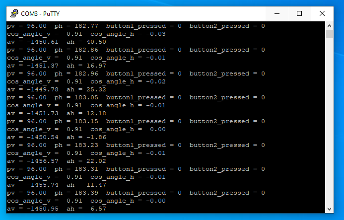
Data transmission displayed in Putty
Result&Conclusion
By completing this final project, we created a Labyrinth Game that was able to be controlled by the wireless sensor. The implementation was done by using two Raspberry Pi Pico W units for VGA display and sensor respectively. We included customization features such that the user will be able to initial conditions of the Game, which will eventually lead to different game experiences. The transmission of the sensor's parameters is realized through UDP, so that the movement of our cube is always smooth and very sensitive, and there is no delay visible to the naked eye, thus obtaining a better performance of the wireless control function. Following are some demonstration pictures of our Labyrinth Game, and the screenshot of the content which WiFi sends.
- According to this picture below we can see that the left half of the screen is the menu interface, where the player can select the desired difficulty as well as the level by clicking the select button up and down, and then confirming it with the confirm button. This picture shows the situation of Level 1, at this time there is no map, there are only small squares and the end.
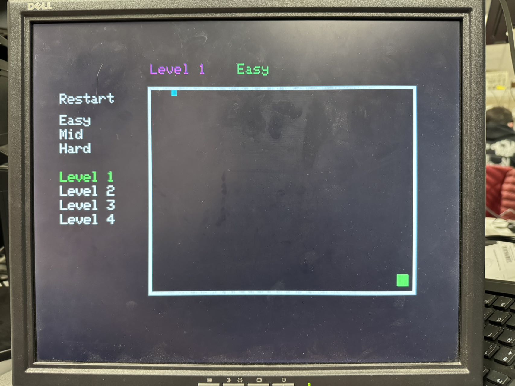
Level 1
- When level 2 is reached, the map will appear on the screen and we can control the movement of the cube by controlling the sensors in order to reach the finish line.
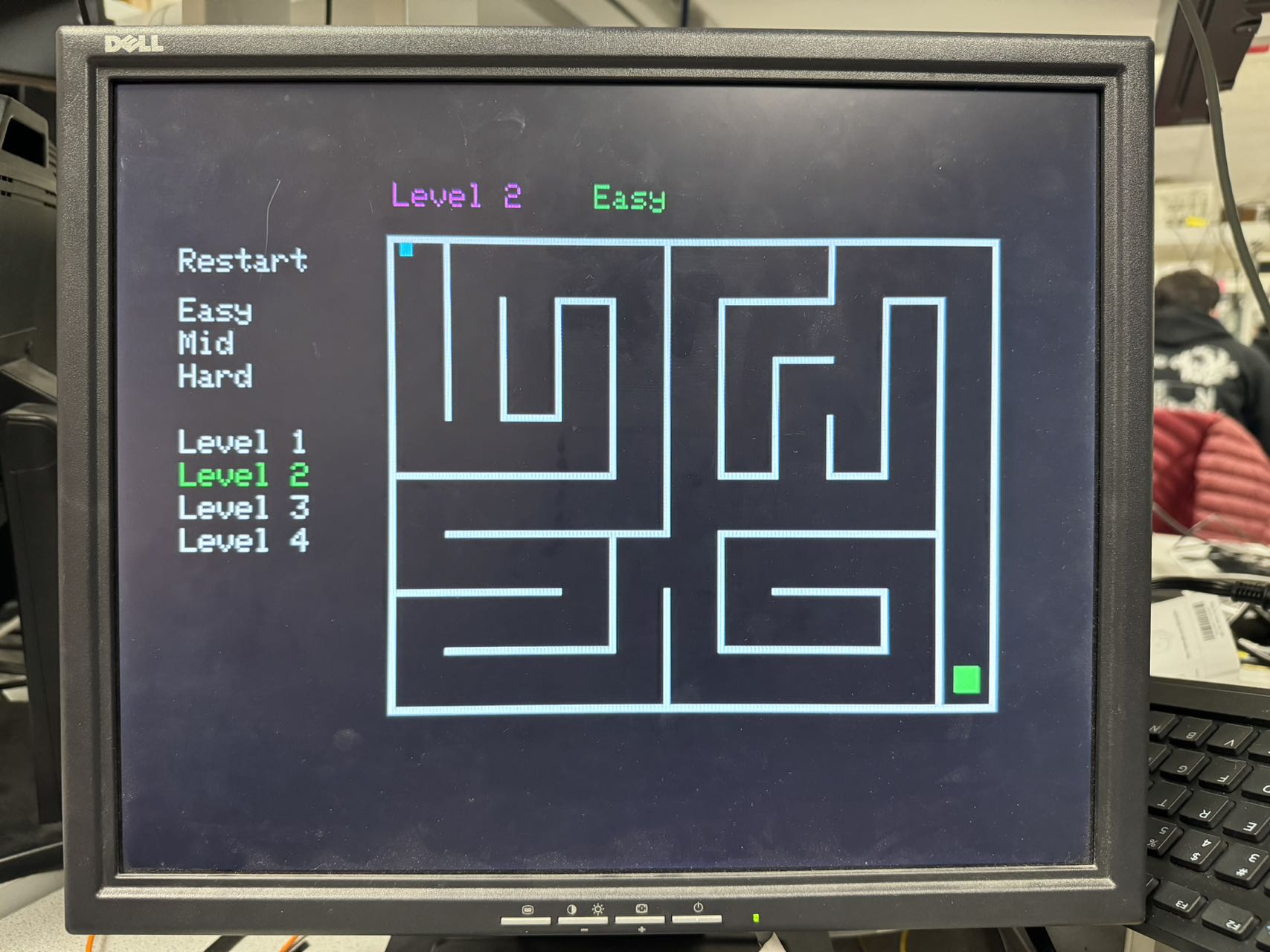
Level 2
- In level 3, we added obstacles to increase the difficulty of the game, that is, the red square area shown in the image when the square touches the obstacle in the process of movement is regarded as a game failure, which to some extent increases the game's fun and playability.
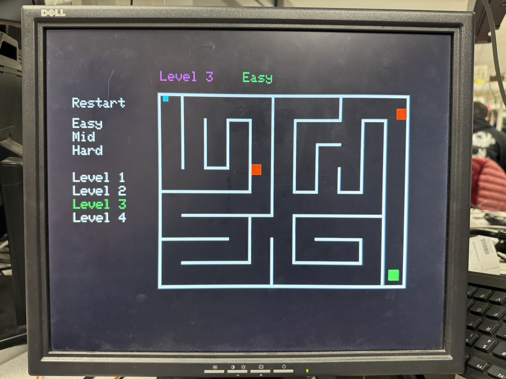
Level 3
- In Level 4, in addition to the obstacles option, we have added a countdown timer, so that if the blocks do not reach the finish line within the time limit, the game is also considered a failure.
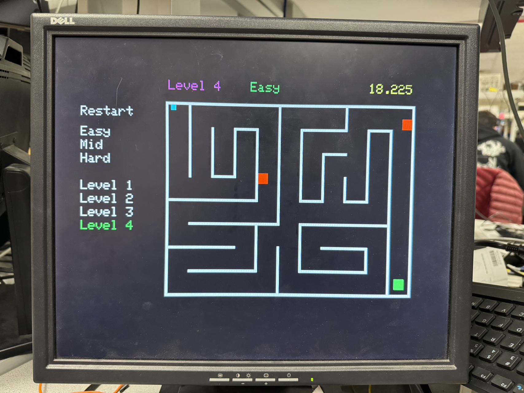
Level 4
In these demonstrations, we can see that different initial conditions and particle directions will lead to very different system behavior. It would definitely be more interesting to add more obstacles into this project, but due to our current design and resource utilization, we were not able to add such features within the time limit.
The Labyrinth Game, developed using Raspberry Pi Pico W microcontrollers, represents a significant achievement in the realm of interactive gaming and technology. This project successfully integrates hardware control, wireless communication, and creative programming to create an engaging and dynamic gaming experience.
Following are some features that we may be able to achieve if given more time:
- Add/remove obstacles to add complexity to the Maze area
- Increase the number of maps to accommodate different types and difficulty settings to increase playability
- Improve the user interface, realize the distinction between the menu interface and the game interface, as well as the jump between the interfaces, to enhance user interactivity.
A lot of parts of our design/architecture were inspired by the Helicopter lab and other previous projects. They have been surprisingly useful when we were considering ways of parallelization. Many thanks to Hunter and Bruce for the abundant resources and documentation!
Appendix
The group approves this report for inclusion on the course website.
The group approves the video for inclusion on the course youtube channel.
Kailing: Software Engineer, Architect, UI/UX Designer, Design Verification Engineer, Documentation
Ziyuan: Hardware Engineer, UI/UX Designer, Design Verification Engineer, Documentation
Yifan: Design Verification Engineer, Documentation