Overview: This project introduces an innovative design for an XY plotter or drawing robot, in which two motors operate along the same axis, facilitating movement in various directions and angles. The uniqueness lies in the synchronized rotation of these motors at different speeds and directions, allowing for versatile positioning.
High-level Design
The Raspberry Pi Pico 2040 Controlled Drawing Robot is an intricate system designed to provide precise control over a drawing mechanism. Comprising essential hardware components, this system is built around the versatile Raspberry Pi Pico 2040 microcontroller. The central processing unit orchestrates the entire operation, from user input interpretation to motor control signal generation.
Hardware Components
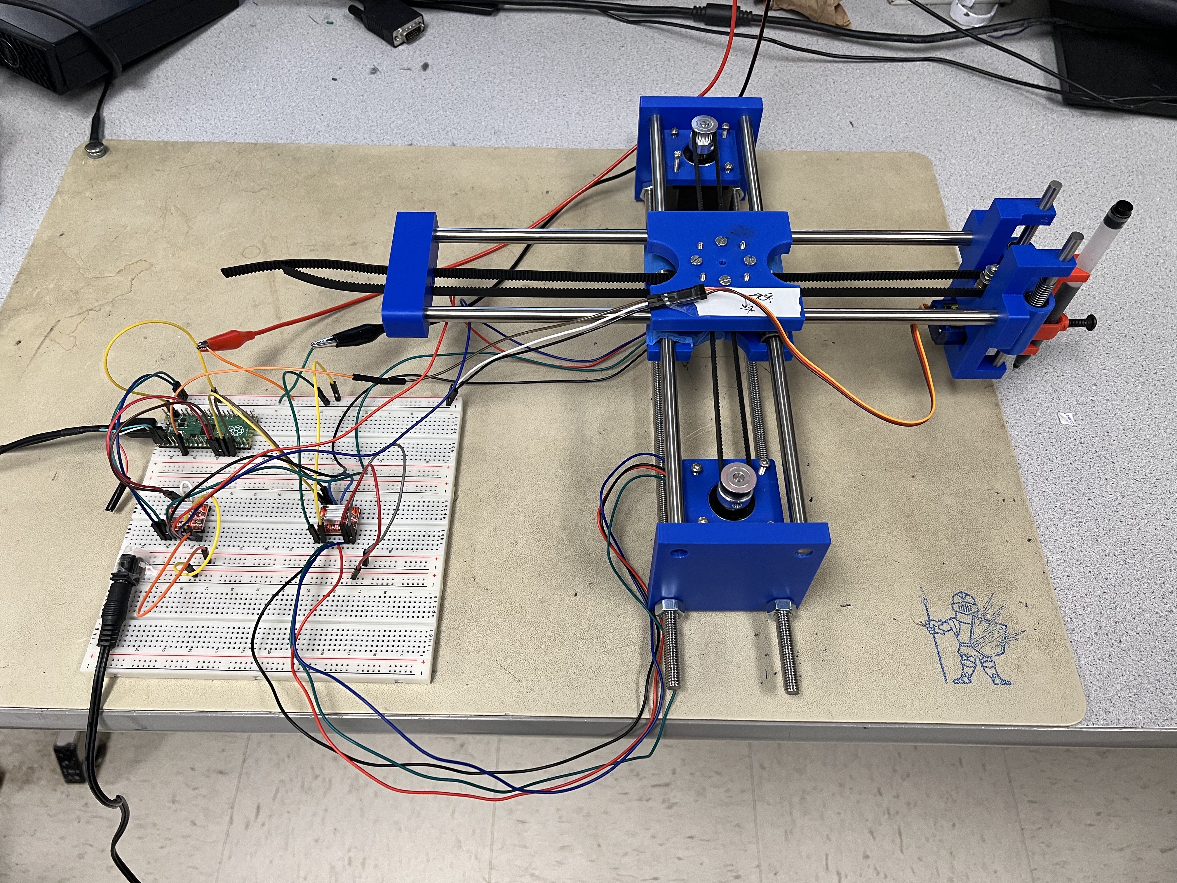
The drawing robot incorporates two stepper motors to navigate in the X and Y directions, similar to a X-Y plotter. These motors are equipped with dedicated motor drivers, forming a bridge between the digital signals generated by the Raspberry Pi Pico and the precise physical movements required for accurate drawing. A servo motor manages the pen's Z-direction, enabling controlled pen elevation and descent. An external power source ensures a stable and reliable power supply for the motors and the microcontroller.
Figure1: Final Product
Motor control
Stepper motor control is a critical aspect of the design. The Raspberry Pi Pico utilizes GPIO pins to generate step and direction signals for each stepper motor. These signals determine the step and direction of each motor's movement, ensuring that the drawing bot accurately follows the desired coordinates. Calibration algorithms are implemented to address any discrepancies in motor movements, contributing to the overall precision of the drawing mechanism.
The servo motor, responsible for managing the pen's elevation, is also controlled through GPIO signals from the Pico. This dynamic control over the pen's position allows for varied drawing patterns.
User Input and Drawing logic
User interaction is a fundamental element of the drawing robot's functionality. The system is designed to interpret user input, typically in the form of English alphabet letters. The Raspberry Pi Pico is pre-programmed with algorithms that translate these inputs into precise motor and servo control commands. The drawing logic includes specific instructions for each letter, incorporating movements like straight lines at 45 and 90-degree angles.
User Interface and Customization
For enhanced user experience, an optional user interface (UI) can be implemented. This UI allows users to input text or select predefined patterns for the drawing bot to recreate. This customization aspect adds versatility to the drawing robot, expanding its capabilities beyond the predefined alphabet.
Testing, Calibration, and Documentation
To ensure reliable and accurate drawing, the system undergoes rigorous testing. Calibration procedures address any potential discrepancies, contributing to the overall precision of the drawing bot. The entire system is accompanied by comprehensive documentation, guiding users through assembly, usage, and troubleshooting processes. This documentation also includes guidelines for customization, empowering users to explore and expand the drawing robot's capabilities.
Hardware Design
Mechanical Design
The most important part of this project is to design a mechanical structure that could move freely in the x direction and y direction. However, none of the team members had any experience in mechanical design. Instead, we searched online and found several options. The most popular one is a structure that uses x-axis and y-axis as their principal axis. In other words, there are two stepper motors in the system and each motor controls one axis separately.
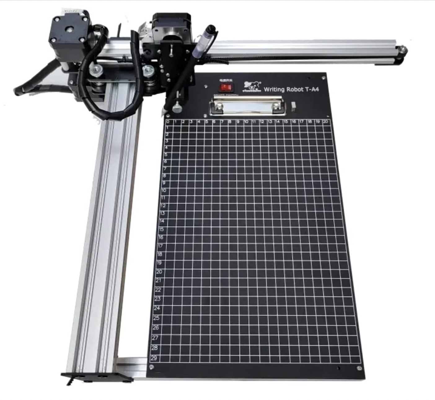
When the x-axis motor starts, it will follow its principal axis and the whole platform moves in x-axis only. One advantage of this design is that the math for the movement is very simple and easy to calculate. For example, if we want to move from point (0,0) to point (10, 20) and the unit is centimeter, you just need to move one motor 10 cm and the other 20 cm simultaneously. Another advantage is that the structure is very easy to design. It will look like the xy plotter in Figure 2. The disadvantage of this design is that since those two motors are in different axes, one motor will be stationary and the other motor has to move along with the stand that holds the pen which creates more vibrations and needs more space to increase the stability.
Figure2: XY plotter
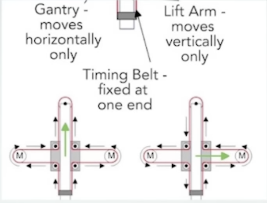
We also found another design option called CoreXY. It is a relatively new design compared with the previous one. The main idea of the design is that two motors move in the same axis and only when two motors rotate together at different speeds and different directions, the whole system can move in any direction or angle. The disadvantage is that the math for the movement is very hard to calculate because the diagonal axes are their principal axes which means when one motor starts, it will move along the y=x axis instead of the x-axis. For example, if we want to move from point (0,0) to point (10, 20) and the unit is centimeter, we need to calculate the corresponding speed, distance and direction for each motor separately.
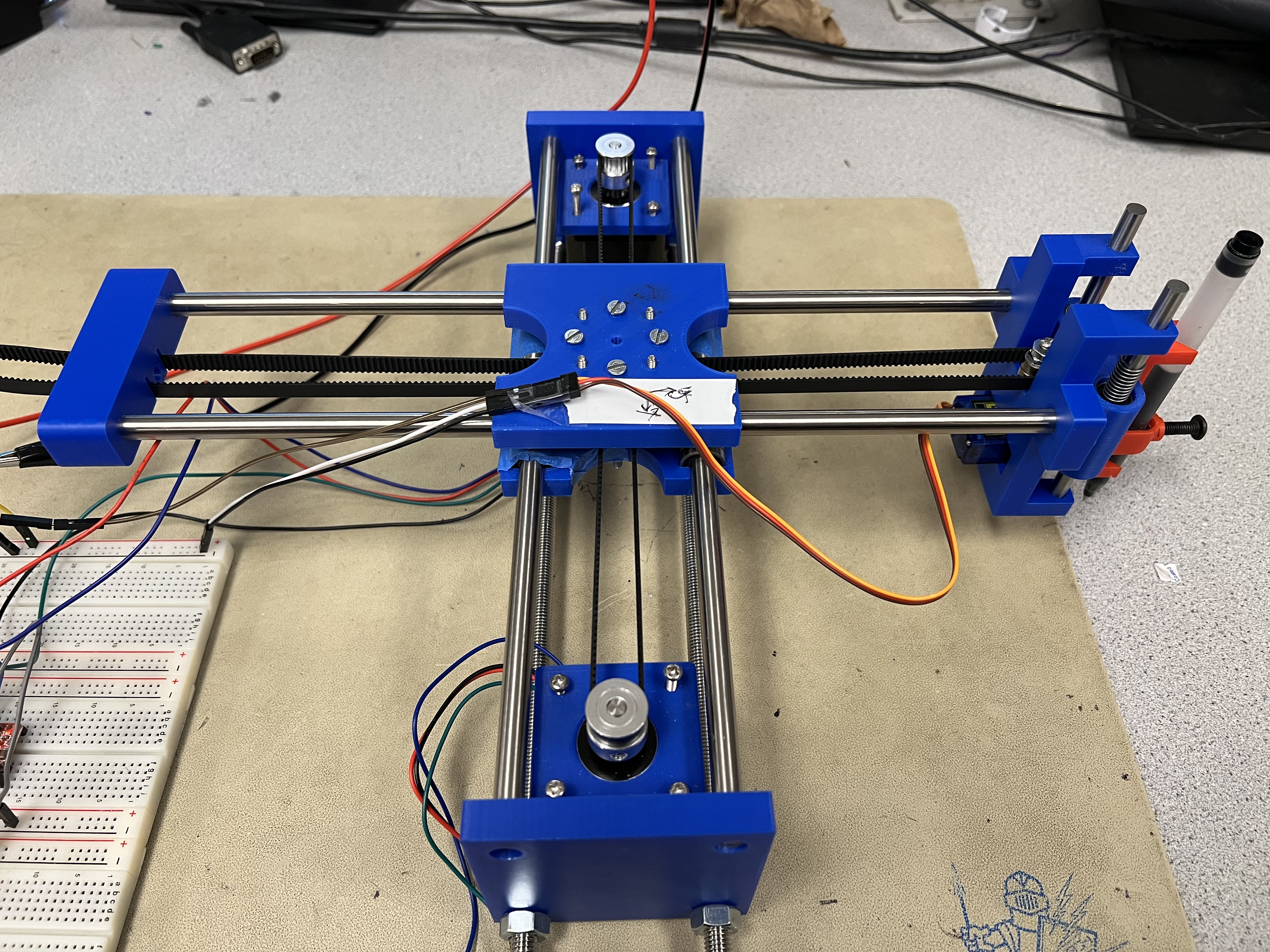
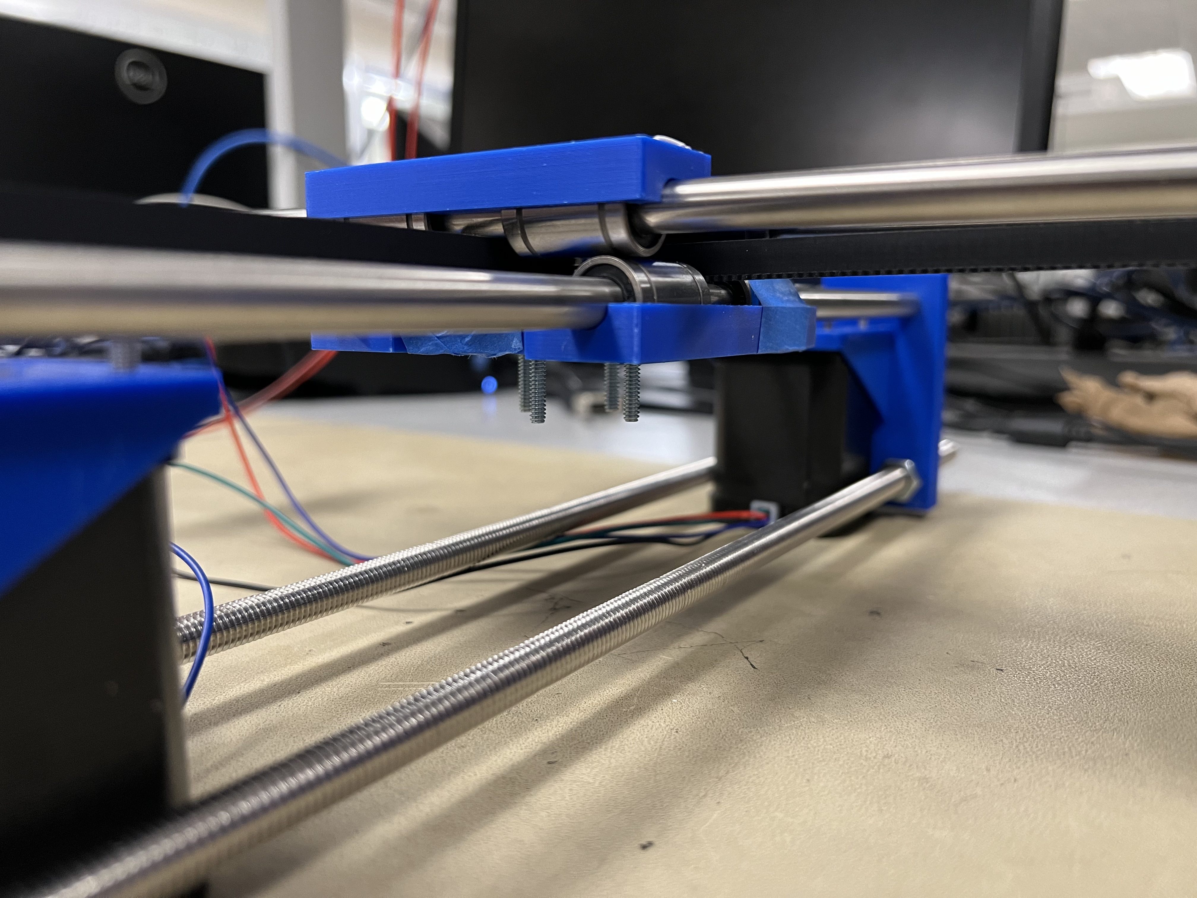
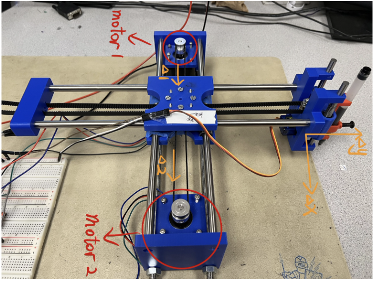
Even though the kinematics is very hard to calculate, there are three major advantages of this design. First, the system can provide higher print speeds. Since both motors move in the same axis, these two motors can be stationary and only the central stand has to move. The stationary motors could reduce mechanical weight and momentum which increased the motors speeds with the amount of inertia provided. Second, with the reduced weight and momentum, the vibrations are reduced and repeatability at higher speeds is increased. Lastly, the whole design takes less space which gives you more printing space with a smaller footprint. Due to these prominent advantages, we chose this design for our project. Figure 3 is the final shape of our design.
Figure 3: Main structure
Since we could not find any existing components that could assemble all the motors, bearings and the rods, we designed and 3D printed all the parts in blue color and the orange pen holder in Figure 3. Let's decompose the whole system.
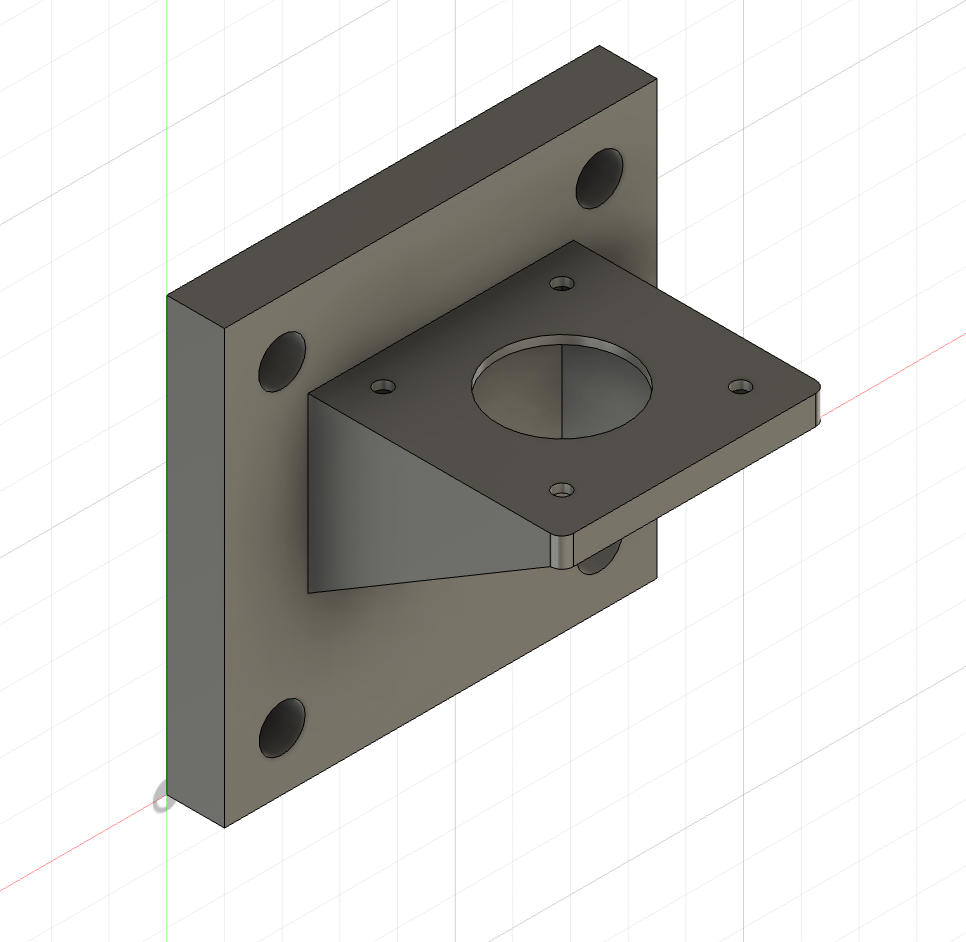
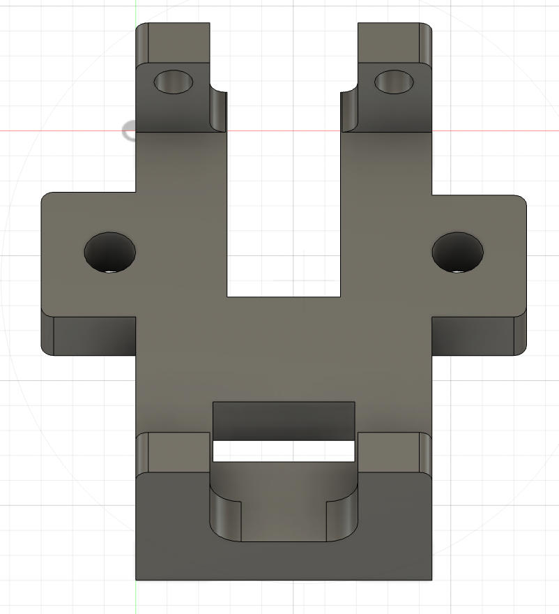
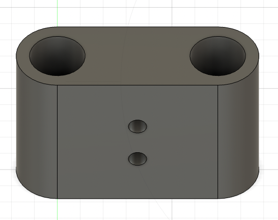
The first component is two identical stands that hold the stepper motors and the rods as shown in Figure 4. The protrude part is used to hold the motor and let the rotation rod pass through. The standing cuboid has four holes. The top two holes are used to carry the rod so that the rods connect the two stands and the central platform can move along the rods. The bottom two holes are used to carry two threaded rods which fix the positions of the two stands.
Figure 4: Stand
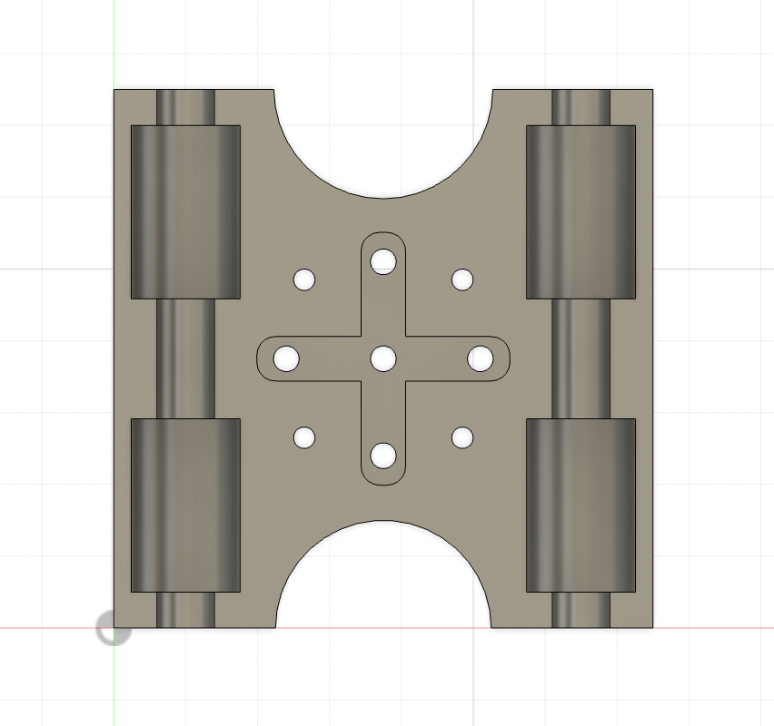
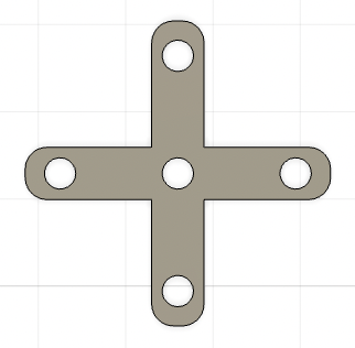
The second component is two bearing holders that form the central platform as shown in Figure 5. This component has four empty spaces which are used to hold four sliding bearings. The bearings passed through the rod so that the platform could slide freely between the stands. The bottom bearing holder connects the two stands and the top bearing holder connects the pen holder and an end part. The two bearing holders are connected by a cross part and some bolts as shown in Figure 7. The cross part is shown in Figure 6. It is used to control the position of the timing Belt that passes through the central platform and connects the motors and the whole system.
Figure 5: Bearing holder
Figure 6: Cross
Figure 7: Central platform
The next component is the pen holder. The two holes on the left and right wings are used to carry the two rods that slide in the horizontal direction. The top two holes are used to carry the rods that pass through two sliding bearings that slide in the z axis. There are two empty spaces in the main body. The top empty spaces are used to fix two bearings so that the timing belt could control the pen holder and the bottom empty spaces are used to put the servo motor which controls the lifting up and down of the pen. The final picture of the pen holder is shown in Figure 8.
Figure 8: Pen holder
The next component is a bearing holder that used to hold the two sliding bearings that pass through the rods in the pen holder. The bearing holder is shown in Figure 9
Figure 9: Small bearing holder
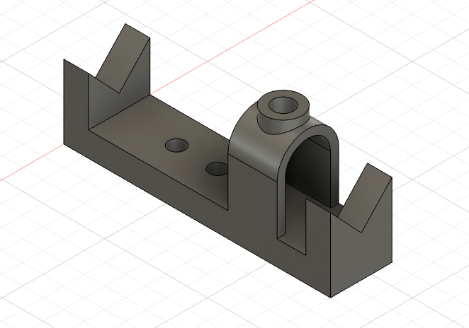
The next component is the pen stabilizer which accommodates the pens with different sizes using a bolt.The pen stabilizer is shown in Figure 10.
Figure 10: Pen stabilizer
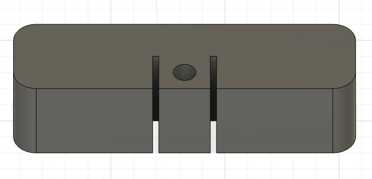
The last component is the end part that fixes two ends of the timing belt. It also stabilizes the rods and pen holder. The slits are used to fix the timing belt. The end is shown in Figure 11
Figure 11: Small bearing holder
The last step to construct the whole system is to use the timing belt to connect different parts. Start with the end part, then go to the motor and then to the pen holder and then to the other motor and then back to the end part. Each time the timing belt changes the direction, it needs to pass through the central platform. Since it needs to connect four components, the time belt needs to enter the central platform four times. How does the timing belt pass through the central platform as shown in Figure 12.
Figure 12: Timing belt
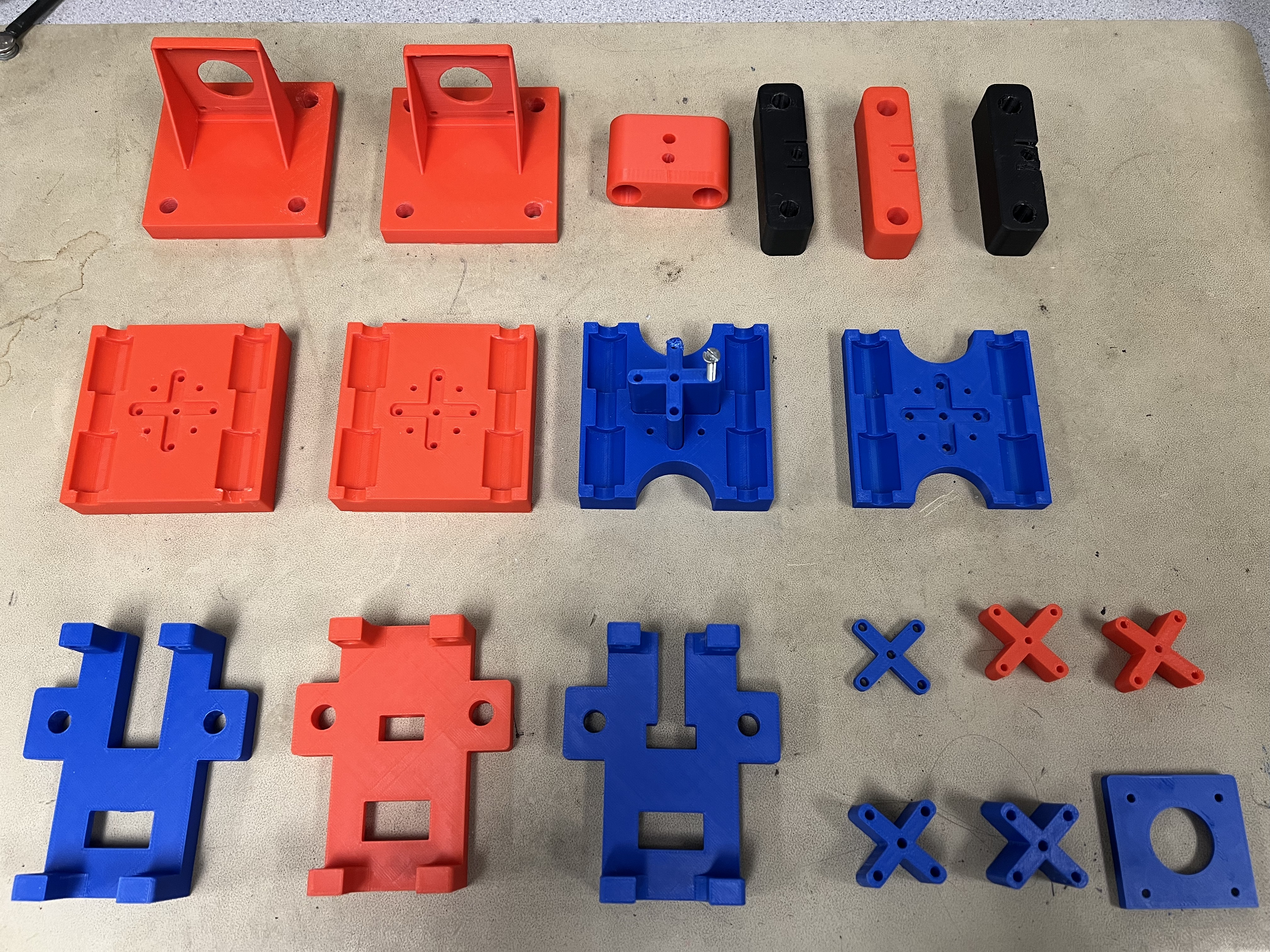
It is very hard to design all these components because the shape and the size are very important. For example, all the holes that pass through the rods have to be aligned so that the rods are parallel to the horizontal or vertical axis. The distance between the holes in the stand are also fixed to exactly 55 millimeters so that the rods can pass through two stands easily. The size of the holds are also very important. Since the rod’s diameter is 8 millimeters, the size of the holes have to be 8.16 millimeters so that the rod can pass through and get stuck. We have designed and printed the same parts several times in order to determine the optimal shape and size. Figure 13 shows the different versions of the design we have printed and tested. Without all these experiments and failure, we could not find the optimal parameters and construct the whole mechanical part.
Figure 13: Differemt versions of the design
Electrical Design
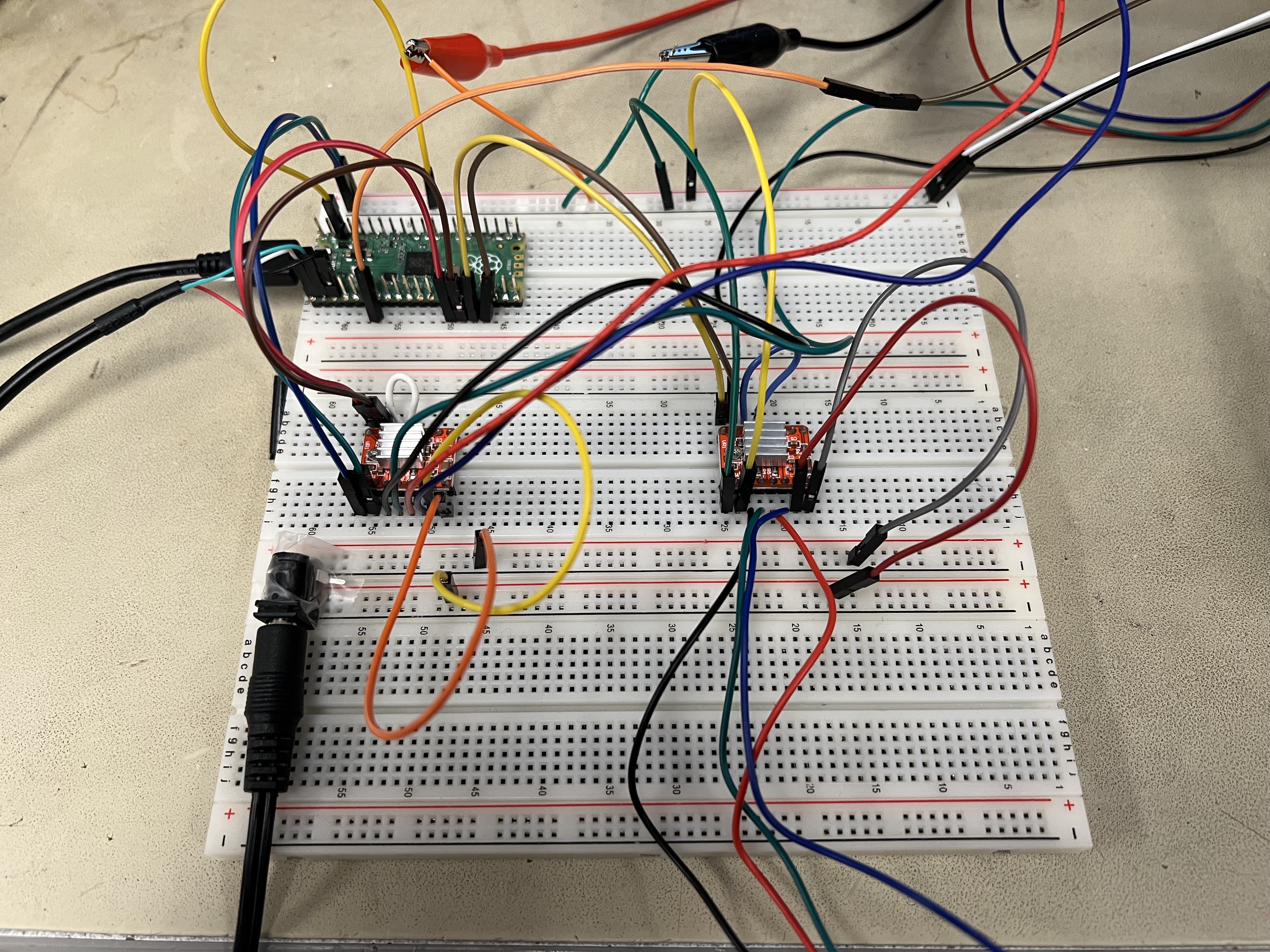
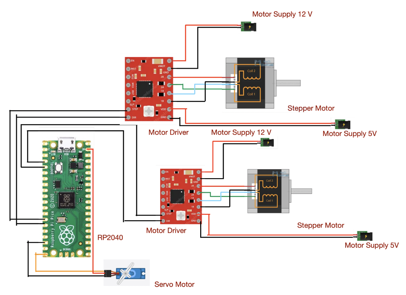
The hardware design is shown in Figure 14. The schematic is shown in Figure 15.
Figure 14: Entire circuit of the system
Figure 15: schematic of the system
To move the position of the pen on the x-y plane, we used two Nema 17 bipolar stepper motors. Each stepper motor consumes 14 V and 2 A. It is very hard to find a power generator that could provide enough current. Instead, we used a charger and socket that output 12 V and 2 A which is enough to power the motors. In order to control the stepper motors, we used two A4988 stepper motor drivers. The motor driver needs a 3-5 Volts power supply to function. Even though the microcontroller provides enough voltage to power the motor drivers, two motor drivers would consume a lot of current and the microcontroller can not sustain that. Instead, we used a power generator which supplies 5 Volts to both motor drivers and shares common ground with the microcontroller. Each motor has four wires which form two coils. (Black and green wires form one coil, red and blue wires form the other coils. The four wires were connected to the 1A, 1B (one coil) and 2A, 2B (one coil) pins in the motor driver. Each motor driver took two inputs from the microcontroller: step and direction. Whenever the step pin changes from 0 to 1, the motor will move one step. When the direction pin receives 1, the motor moves counterclockwise and when the direction pin receives 0, the motor moves clockwise. We also used a SG90 servo motor to control the lifting up and down of the pen holder. The servo motor is controlled by the PWM signal from the microcontroller.
Software Design
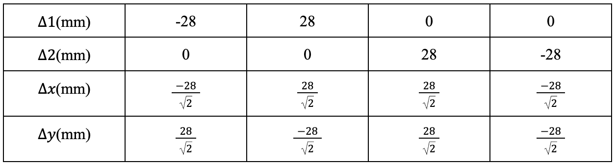
Since CoreXY uses a different coordinate system, it is very critical to determine the relationship between the movement in the two motors and the movement of the pen in order to control the pen position accurately. First, we did several experiments. We only rotate one motor one cycle each time in clockwise direction and counterclockwise direction and repeat with the other motor. The result is shown in Table I. The measurement is based on a specific axis we chose and it is shown in Figure 13.
Figure16: Coordinate System
Table I: Experiment result of motor movement for two motors
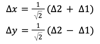
From this table we determined these two equations.
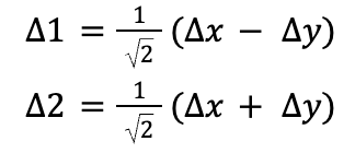
And we can use this equation to determine the relationship for Δ 1 and Δ 2 in terms of Δ x and Δ y
If we know the x position and y position of the start point and the end point of the curve under the axis system in Figure ?, using the above two equations, we can determine the distance each motor needs to move in order to draw the curve. Then, since we chose the full step options, after precise measurement, we determined that each rotation corresponds to 200 steps and 28 millimeters in distance. In other words, one step corresponds to 28/200=0.14 millimeters distance. Using the calculated distance of 1 and 2, we can determine the steps each motor needs to rotate.
Since the two motors need to move and stop synchronously, we can use their steps to calculate the speed they have to move. However, the motor driver does not receive the input for motor speed; instead it only receives the input of step. The time difference between each step is inversely proportional to the motor speed. If we know the relationship between the speeds of motor 1 and motor 2, we can use that to determine the time interval between each step for both motors. And the rotation direction is purely determined by the 1 and 2. If 1 is positive, motor 1 should rotate counterclockwise and if 1 is negative, motor 1 should rotate clockwise. Same rule applies to motor 2.
With all this information, we can write a for loop for each motor that repeats the number of steps times. Within each iteration of the loop, the sign pin gets high first, and waits for the corresponding time interval, and the sign pin gets low, and waits for the corresponding time interval. Since we want both motors to move synchronously, we selected core 0 to control motor 1 and core 1 to control motor 0 so that we can start the core 0 and core 1 at the same time and both motors will move synchronously. Finally, we can write a function called drawxy that takes the initial x position and y position and the final x position and y position as input and draws the lines corresponding to the initial and final positions.
With this function, if we want to draw a circle, we can calculate the x and y positions for each point in the circle and store them in an array. Then, we can loop through each point in the array and call the drawxy function with those points as input. And this would draw the circle properly.
If we want to print letters with various sizes, we need to determine how the pen moves if we want to start at lower left and end at lower right. For example, if we want to print the letter “C”, the pen needs to move up first, and move right, and move left, and move down and move right. Then we can write a function called drawC which takes the font size as input and moves based on the above sequence.
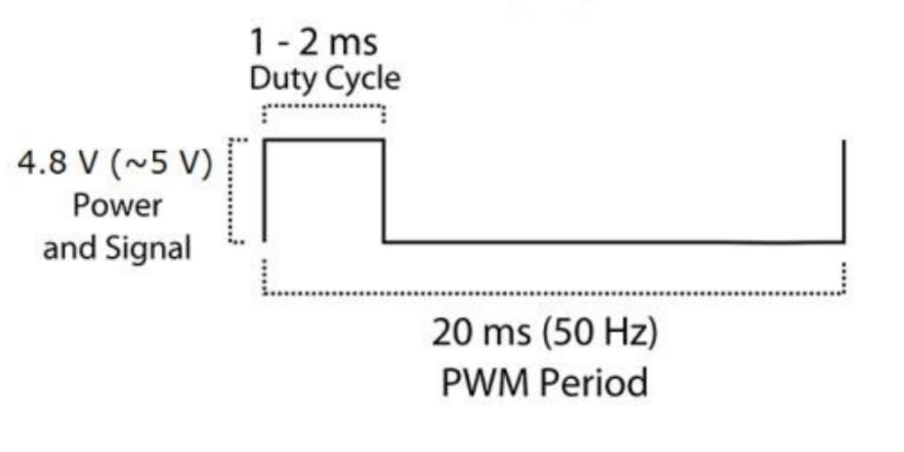
To control the servo, we resort to PWM. According to the image below from the datasheet, we need a PWM frequency of 50Hz, which is why 250 and 10000 were picked when setting up the PWM, as 125MHz/250*10000=50Hz.
Results
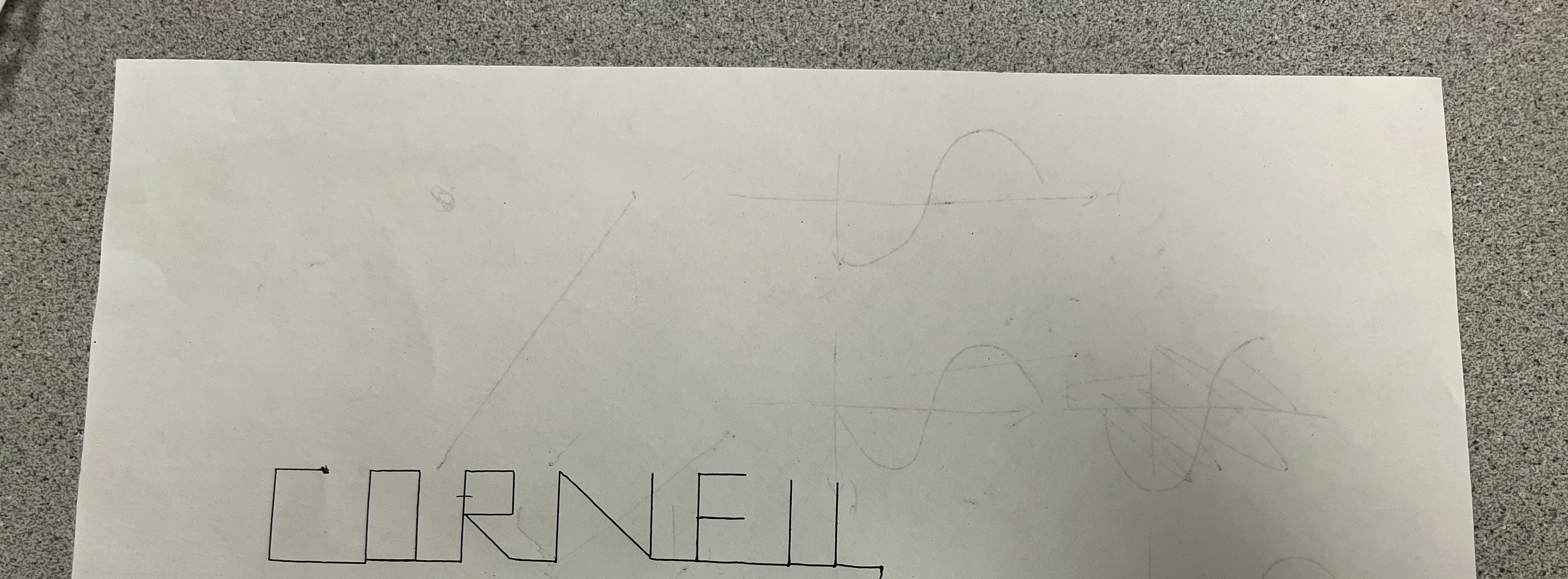
Our mechanical parts work really well. With the motor, the whole system could easily move in the x-y plane. After the software implementation, we could accurately print any letters with various font sizes on the paper. As shown in Figure ?, we successfully printed the word “Cornell” using the drawing robot.
Figure 17: Printed Letters
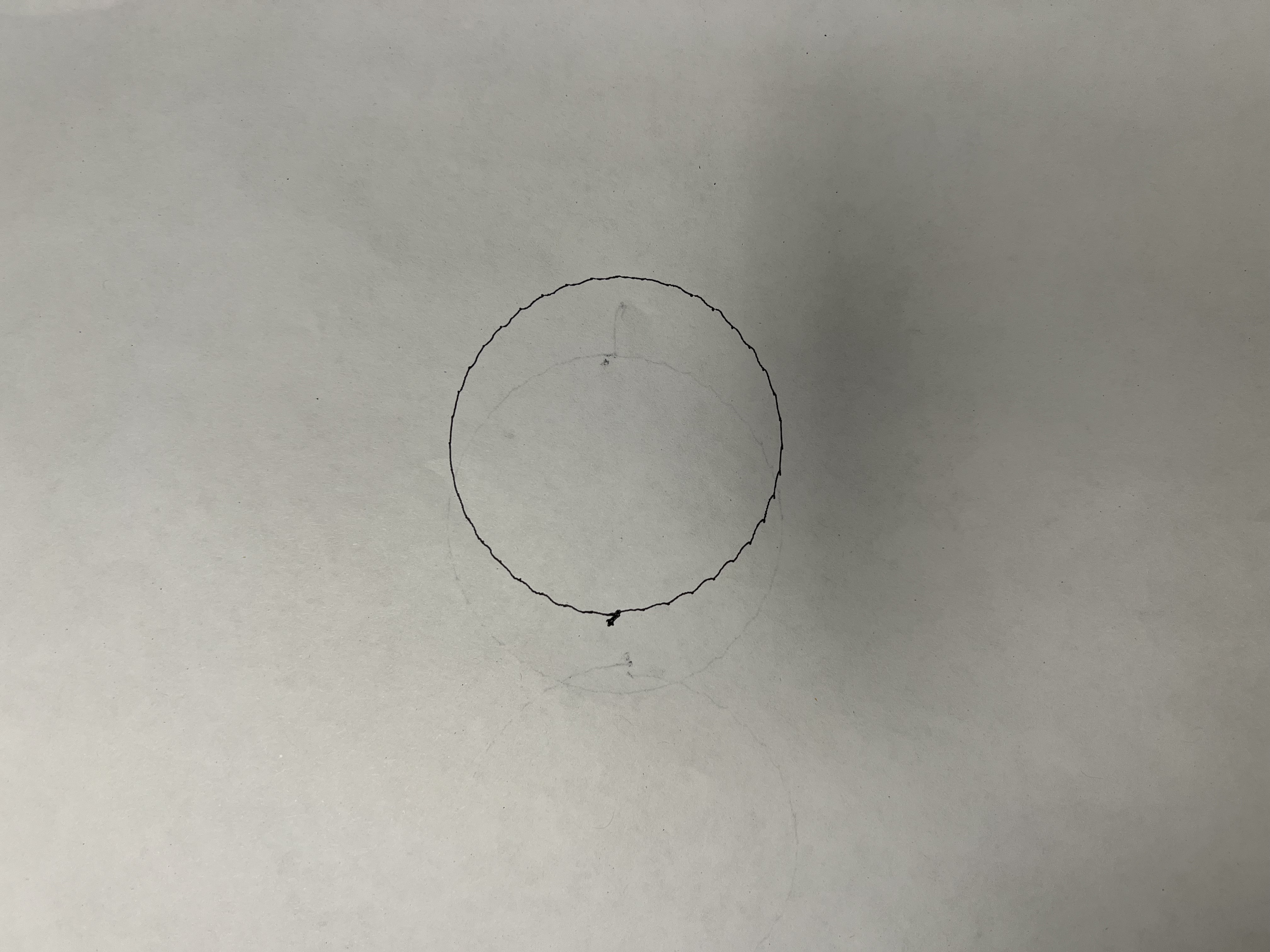
In addition, we successfully drew a circle using the robot. The circle consists of many infinitesimal lines with various angles which means we could draw any curve with different size and different angles.
Figure 18: Circle
Below is video that draws a circle:
Below is our demo video:
Based on the printed words and circle, we believe that our implementation is pretty accurate. The drawing robot could correctly draw any plots or print any letters or words. In terms of the speed, the robot executes very fast without hesitation and almost has no interrupt. We enforced safety in the design by making sure the mechanical parts are assembled correctly and they are very stable. We also make sure the motors will not suddenly accelerate and move very fast so that no components will break midway and cause damage. As for usability, our system requires no skills about mechanical design, coding and hardware. The users only need to input the font size and the letter they need. It is very handy to use this drawing robot to type any words or draw a simple graph.
Conclusion
In reflection, our XY plotter or drawing bot design has not only met but exceeded our expectations by achieving higher print speeds, reducing vibrations, and optimizing spatial efficiency. Throughout the development process, we have remained committed to adhering to applicable standards and ethical considerations, ensuring our project aligns with legal and intellectual property norms. As we consider future iterations, there is room for improvement, particularly in simplifying the complex kinematic calculations to enhance user-friendliness.User feedback will be instrumental in guiding refinements to address any unforeseen challenges and further optimize performance. Our design stands in compliance with intellectual property standards, as we have diligently avoided unauthorized use of code or designs and steered clear of patent or trademark disputes.Looking ahead, our future scope includes the ambitious goal of enabling the plotter to draw more complex and abstract figures. This expansion aligns with our commitment to ongoing innovation and user satisfaction. We remain dedicated to upholding the highest standards of ethical design and intellectual property integrity in our pursuit of enhancing the capabilities and versatility of our XY plotter or drawing bot.
Future Work
For future work on this problem,, we can explore leveraging the microstepping feature of the motor driver. By reducing the length of each step, we can significantly enhance the accuracy and smoothness of the curves drawn by the robot. Moreover, adopting microstepping has the potential to improve the stability and mitigate the noise associated with stepper motors, rendering this project more suitable for family or workplace settings. Currently, our robot is capable of drawing curves with predefined inputs. To further enhance its usability and empower it to draw arbitrary graphs, we propose integrating a Picamera with our system. By employing OpenCV on a Raspberry Pi 4, we can implement the Canny Edge Detection algorithm to accurately identify the edges of a plot in real-time. Subsequently, via the UART peripheral, the Raspberry Pi can transmit the edge data, comprising the points of interest, to the Pico. The Pico, in turn, controls the system to precisely reproduce the graph, offering a versatile and user-friendly drawing experience.
Appendix
Permissions
The group approves this report for inclusion on the course website.
The group approves the video for inclusion on the course youtube channel.
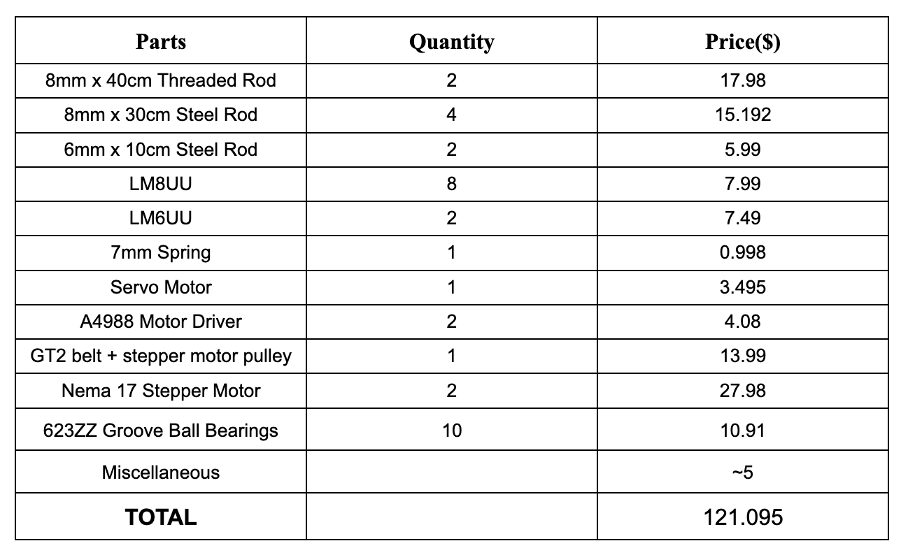
Bill of Materials
Work Distribution
Mechanical: Mahathi Andavolu, Koushani Das, Dengyu Tu
Hardware: Mahathi Andavolu, Koushani Das, Dengyu Tu
Software: Mahathi Andavolu, Koushani Das, Dengyu Tu